Article

Design of Sensor Data Processing Software for the ISO 23150 Standard: Application to Autonomous Vehicle Software

1
School of Mechanical Engineering, Pusan National University, Busan 46241, Republic of Korea
2
Korea Automotive Technology Institute (KATECH), Cheonan 31214, Republic of Korea
3
Department of Future Automotive Engineering, Gyeongsang National University, Jinju 52828, Republic of Korea
*
Authors to whom correspondence should be addressed.
Electronics 2023, 12(21), 4505; https://doi.org/10.3390/electronics12214505
Submission received: 25 September 2023 / Revised: 30 October 2023 / Accepted: 31 October 2023 / Published: 2 November 2023

Abstract

:
The ISO 23150 standard defines the logical interface between sensors and fusion units. To apply this standard to actual vehicles, software is required to convert sensor data into ISO 23150-compliant sensor data. In this study, we developed sensor data processing software to provide ISO 23150-compliant sensor data to autonomous vehicle software. The main contributions of this study are as follows: First, the safety of the software is considered, and its structure and error detection method are designed to minimize the impact of errors. Second, the software structure is in accordance with the ISO 23150 standard, and a framework structure is designed with convenience in mind. Third, we considered its compatibility with adaptive AUTOSAR by designing a data delivery service using SOME/IP communication. We evaluated the security and data delivery delay of the software on a controller used in an actual vehicle and noted high security and real-time performance. The evaluation results demonstrated the feasibility of this method for real-world vehicles. Our study can serve as a basis for advancing autonomous driving technology in the context of ensuring software safety.

1. Introduction

Autonomous driving technology involves the perception and evaluation of the environment around a vehicle, with strong emphasis on the performance and reliability of these perception capabilities [1,2]. For example, if a vehicle fails to accurately perceive elements on the road, such as other vehicles, pedestrians, signals, and signs, it can lead to misjudgment and accidents [3,4,5]. Advanced autonomous driving technologies employ a variety of sensors, each with different sensing capabilities, to comprehensively assess the environment around the vehicle [6,7,8]. This multisensor approach enhances perceptual information, introduces redundancy, and ensures a high degree of accuracy and reliability in understanding the environment [9,10,11].
However, the use of different sensor setups poses challenges when sensor-dependent autonomous driving software is adapted to actual vehicles. With the increase in the size and complexity of autonomous vehicles, there is a need to develop and validate them in simulated environments to reduce development and testing costs [12]. Simulation environments cannot perfectly replicate the nuances of real-world sensor characteristics, leading to differences between the simulated and actual vehicle environments [13]. Therefore, adapting software to an actual vehicle environment is imperative when transitioning autonomous driving software developed in simulation environments to real vehicles. This transition is associated with significant cost and effort.
To mitigate this problem and minimize sensor dependency in the software, the International Organization for Standardization (ISO) has introduced the ISO 23150 standard [14]. This standard defines a sensor interface for data transfer between sensors and fusion units or software components (SWCs). The sensor interface categorizes sensor data into different levels, including detection, features, and objects, based on the characteristics of the various sensors. By standardizing the exchange of sensor input and output data between sensors and SWCs, this framework reduces sensor dependency in software development, resulting in cost and time savings.
Owing to these benefits, the ISO 23150 standard was adopted by AUTOSAR and OSI [15,16]. Linnhoff et al. used the ISO 23150 standard in their technology-independent modular model architecture for autonomous driving perception sensors [17]. Kurzidem et al. used ISO 23150 in their systematic methodology to analyze the logical system architecture of an ADAS while considering uncertainties to determine the performance limits [18]. Haider et al. also considered the ISO 23150 standard when developing a LiDAR model for virtual testing and validation of an advanced driver assistance system (ADAS) [19]. However, existing research does not address methods for applying the ISO 23150 standard to real vehicles. The implementation of this standard in real vehicles requires sensors that comply with the standard; such sensors have not been commercialized, and incorporating sensor data processing functions into sensors can make them expensive. Therefore, real vehicles require sensor data processing software that conforms to this standard.
Research on sensor data processing methods has mainly focused on improving perception performance by studying methods for processing specific sensor data or by combining data from different sensor sets [20,21,22,23,24]. In addition, much of the research on autonomous driving software has aimed at improving the performance of autonomous driving software platforms and architectures [25,26,27,28]. There is a lack of research on designing software for processing sensor data in real vehicle systems and on the application of the ISO 23150 standard to real vehicles.
In this context, this study designed software to process sensor data and provide ISO 23150-compliant sensor data to SWCs. The contributions of this study to the ISO 23150 standard are as follows: First, we designed the software to provide sensor data for autonomous driving with convenience in mind. Specifically, a framework for sensor data processing functions is designed to minimize the effort required when adding new sensors or changing the sensor data processing algorithms.
Second, with software security in mind, the software design is based on a multi-process approach. We designed a function that detects errors in the sensor data processing in real time and notifies the autonomous driving software. This minimizes the impact of possible errors in the sensor data processing process and ensures the safety of the software by detecting them.
Third, to validate the applicability of the sensor data processing software, we performed verification using a controller that is used in actual vehicles. In particular, we evaluated the safety of the sensor data processing software and the real-time performance of the data provision function to verify its applicability.
The rest of this paper is organized as follows: Section 2 describes the scope of the ISO 23150 standard and the proposed sensor interface. Section 3 describes the software structure and functions of the interface. In Section 4, the proposed sensor interface is configured as a controller for a real vehicle, and its applicability is verified. Finally, Section 5 presents the conclusions and limitations of this work.

2. ISO 23150 Standard in Autonomous Driving Software

Figure 1 shows an example of autonomous driving software with the logical interface of the ISO 23150 standard. The fusion unit configured in the autonomous driving software receives sensor data in the format specified in the logical interface. The logical interface specifies a modular semantic representation of the sensor data and sensor status information. It defines the detection, feature, and object-level interfaces for providing the sensor data. The logical interface also defines the sensor performance and health information interfaces for providing sensor information.
The detection and feature interfaces used to provide sensor data are defined according to the sensor characteristics. In particular, the camera and ultrasonic interfaces provide shape and covariance as features, respectively. However, the LiDAR and radar interfaces do not provide data to be used as features. The object interface is a common interface used by all sensors and comprises interfaces that provide potentially moving objects, road objects, and static objects.
The sensor performance and health information interfaces, which provide sensor information, are used by all sensors. The sensor performance interface provides information such as the sensor’s measurement direction, measurement range, installation location, and object detection rate. Sensor health information includes sensor temperature, voltage, defects, and calibration information. By standardizing the sensor data and information provided to the fusion unit, these logical interfaces minimize the dependence of the fusion unit on sensors, thereby minimizing the cost and effort required for development.
To maximize the effectiveness of the logical interface, the sensor must support a logical interface, such as Sensor 3 in Figure 1. However, generally, raw or preprocessed sensor data, such as those from Sensors 1 and 2, are provided through interfaces defined by each developer. Therefore, to apply the ISO 23150 standard to current autonomous driving software, a sensor data processing function is required to receive and process the sensor data and provide it to the fusion unit through a logical interface.
Software that performs the sensor data processing function requires very high real-time performance and reliability because it is responsible for providing sensor data. In addition, it should be easy to add sensor models or modify the sensor data-processing algorithms to minimize development costs and difficulty. In addition, to provide sensor data to the fusion unit in compliance with the logical interface, an inter-process communication function must be designed based on service-oriented communication. In particular, for the fusion unit to provide only the required sensor data and information, the service providing the data and information for each sensor must be configured independently.

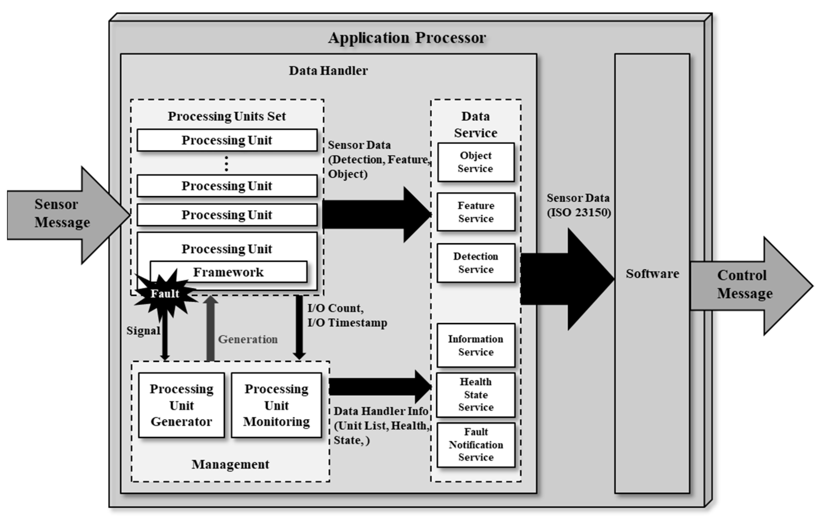
3. Software Architecture Design
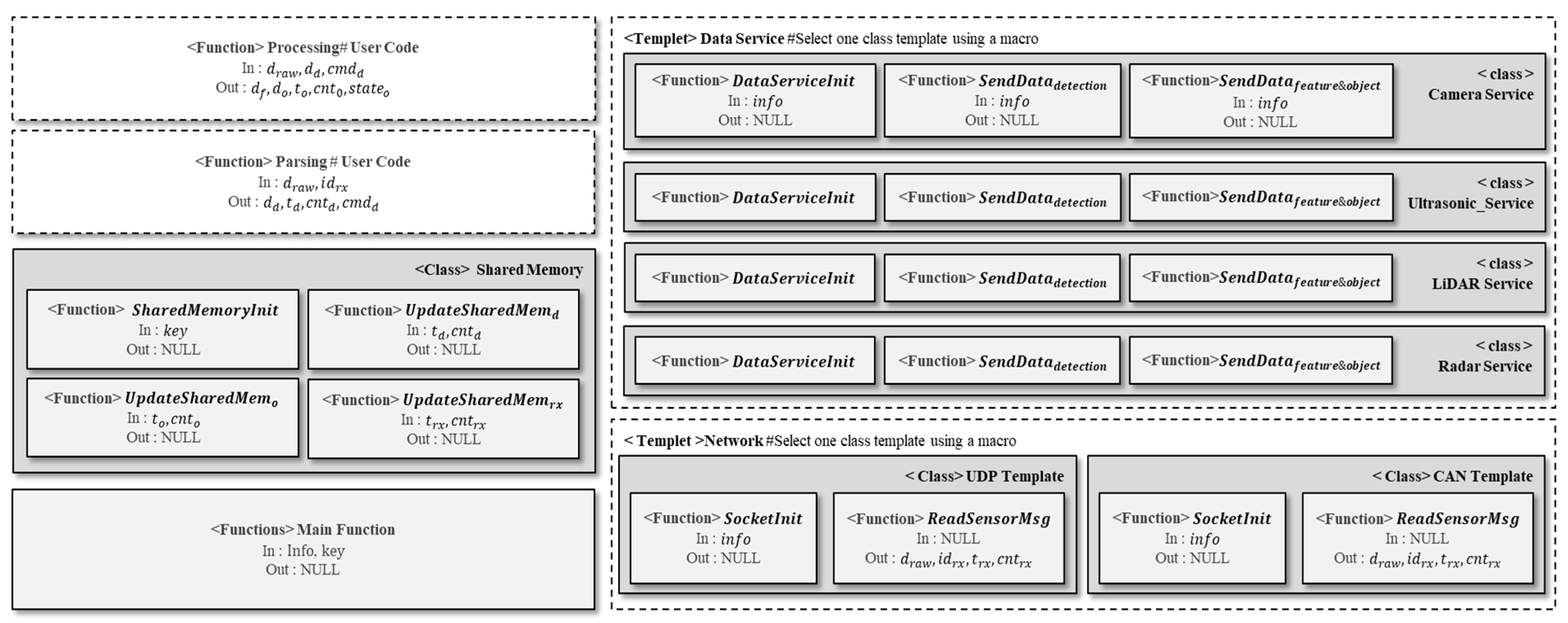
In this study, we designed software that processes sensor messages from a Linux-based autonomous driving controller and provides them to a fusion unit in compliance with the ISO 23150 standard. We designed the structure and function of the software considering the safety of the software and convenience of development. In this study, the software that processes sensor messages and provides them to the fusion unit in compliance with the ISO 23150 standard is called a data handler. The set of fusion units and SWCs constitutes the autonomous driving software. Figure 2 shows the structure and functions of the data handler designed in this study. The data handler comprises a set of processing units, a data service, and a management unit.
The processing unit set is responsible for receiving sensor messages and generating sensor data at the detection, feature, and object levels, as specified in the ISO 23150 standard. A processing unit set comprises multiple processing units, and a single processing unit receives and processes messages from a single sensor. Therefore, the processing unit set contains the same number of processing units as the number of sensors used in autonomous driving. Each processing unit is executed in parallel, and in our study, it is executed as a multiprocess unit to ensure software safety.
The management unit comprises a processing unit generator and a monitoring function. The processing unit generator creates as many processing units as the number of sensors used in autonomous driving to form a set of processing units. The monitoring function monitors the health status of the processing unit and detects defects caused by runtime errors. To achieve this, the monitoring function receives a signal initiated when a processing unit is terminated due to a runtime error and detects the fault. It also collects the function execution count and timestamps delivered by the processing unit.
The data service is responsible for providing the detection, feature, and object data generated by the processing unit, the fault detection information provided by the management unit, and the health state of the processing unit to the autonomous driving software. It also provides details of the processing units that comprise the processing unit set for the autonomous driving software. In particular, a service that provides detection, feature, and object data complies with the header and data formats of the logical interface of the ISO 23150 standard. Other services are transmitted in a brief and arbitrarily defined format.
The data service is described in detail in Section 3.1, the processing unit in Section 3.2, and the management unit in Section 3.3.

3.1. Data Service

The data service of the data handler provides the sensor data and processing unit information to the autonomous driving software. In this study, SOME/IP communication was used to ensure compatibility with adaptive AUTOSAR-based autonomous driving software and ease of development. Figure 3 shows the content configuration of the SOME/IP-based data service and the service instance ID for subscribing to the content. The data service comprises a SOME/IP server. The data service comprises detection, features, objects, HealthState, and FaultNotification content.
The content of the data service is divided into data and information. Detection, feature, and object contents are classified as Data, and HealthState and FaultNotification contents are classified as Info. Content classified as data provides sensor data to the autonomous driving software. Content categorized as info provides information from the processing unit to the autonomous driving software. Each content provides sensor data processed by a single processing unit and information from a single processing unit. Therefore, if the number of sensors is n, each content comprises n pieces. The desired content can be accessed through the Service Instance ID, which combines the type and model of the sensor to be provided, the classification of the information to be provided, and the content name.
Detection, feature, and object contents provide each level of sensor data generated periodically by the processing unit to the autonomous driving software. This content uses SOME/IP event notifications to transmit each level of sensor data as generated. All the data transmitted by the detection, feature, and object contents conform to the detection, feature, and object interfaces of the logical interface of the ISO 23150 standard. Data services that provide camera and ultrasonic sensor data are enabled for both detection, feature, and object contents. For data services that provide LiDAR and radar sensor data, feature content is disabled, and only detection and object contents are enabled.
The HealthState content provides the processing unit with health information. It periodically provides the status information of the processing unit to the autonomous driving software using the SOME/IP event notification transmission method. The HealthState message, which provides the status information of the processing unit, contains headers and data fields. The header field contains the sensor type, model, installation location, sequence ID, and message transmission time. In particular, the header field is shared by all the contents. The data field comprises health state data, which contains information about sensor message reception events and data generation events with a time frame of 1 s. The health data comprise a list of the number of times each event occurred in 1 s and the time for which each event occurred. Each event occurrence time datum is stored in a list based on the number of message reception events.
The FaultNotification content is used to notify the autonomous driving software when the processing unit is forced to shut down due to a fault. The notification content notifies the autonomous driving software of a fault in the processing unit in real time using the event notification transmission method. Fault information is provided to the autonomous driving software via a fault notification message. The fault notification message comprises a header and a data field. The header field is common and the same as the other messages. The data field contains information pertaining to the time at which the management unit detects a fault in the processing unit.

3.2. Management Unit

Algorithm 1 presents the pseudocode of the management unit. The management unit is the entry point for the data handler and takes as input the configuration file F i l e c o n f , which contains the sensor information to be processed by the data handler. The management unit comprises initialization and function execution phases. The initialization phase is shown in Lines 2–5 of the pseudocode in Algorithm 1, and the function execution phase is shown in Lines 6–14.
Algorithm 1. Management Unit
1: function   M a n a g e m e n t U n i t ( F i l e c o n f )
2:/* Read the information of the sensors used for autonomous driving. */
3: I n f o L i s t R e a d C o n f i g u r e F i l e ( F i l e c o n f )
4:/* Initialize the shared memory to receive the status of the processing unit. */
5: K e y L i s t S h a r e d M e m o r y I n i t ( I n f o L i s t )
6:/* Read sensor information one by one (iterating for the number of sensors). */
7: for   i n f o   in   I n f o L i s t   do
8:  /* Execute the processing unit for a specific sensor. */
9:   p i d P r o c e s s E x e c u t i o n ( P r o c e s s i n g U n i t , i n f o , k e y )
10:  /* Execute the fault monitoring unit to detect fault in the processing unit. */
11:   T h r e a d E x e c u t i o n ( F u a l t M o n i t o r i n g U n i t , i n f o , p i d )
12:end for
13:/* Execute the Health Monitoring Unit to receive the status information of the processing unit. */
14: H e a l t h M o n i t o r i n g U n i t ( I n f o L i s t , K e y L i s t )
15: return   N U L L
In the initialization phase, the data handler initializes the resources of the management unit using the sensor information to be processed. To this end, we read f i l e c o n f with the ReadCofigureFile function and initialized the sensor information list object InfoList. Subsequently, the SharedMemInit function initializes the shared memory to be used to receive the health state information from the processing unit set. At this time, the shared memory has a size proportional to the number of sensors included in the InfoList.
In the functional execution step, as many processing and fault monitoring units as the number of sensors in InfoList are executed. To achieve this, we sequentially extracted single-sensor information, Info, from InfoList. Subsequently, using the ProcessExcution function, a processing unit was executed to process the data of the sensor model stored in the Info. At this time, the processing unit is executed as a process and returns the PID of the executed processing unit. The returned PID is used by the fault-monitoring unit to detect faults in the processing unit executed in the same step. The fault-monitoring unit is executed as a thread using the ThreadExecution function. Finally, a health monitoring unit is executed to monitor the health state of the processing unit set. The health monitoring unit is not executed in parallel but in the main thread.
Algorithm 2 presents the pseudocode for the fault monitoring unit function. This function is responsible for detecting faults in the processing units and notifying the autonomous driving software about these faults. In this research, only faults resulting from runtime errors in the processing units are detected. To achieve this, the function listens for the SIGCHLD signal of a specific processing unit to detect faults. Detecting additional types of faults would require monitoring signals other than SIGCHLD or implementing additional fault detection methods.
Algorithm 2. Fault Monitoring Unit
1: function   F a u l t M o n i t o r i n g U n i t ( i n f o , p i d )
2:/* Initialize the service for notifying SWC of Processing Unit faults. */
3: F a u l t N o t i f i c a t i o n S e r v i c e I n i t i a l i z a t i o n i n f o
4:/* Configured as an infinite loop to run until a fault occurs. */
5: while   t r u e  do
6:  /* Receive signals sent from the Processing Unit. */
7:   S i g N u i m W a i t S i g n a l ( p i d )
8:  /* If the received signal is the SIGCHLD signal, measure the fault detection time and then notify SWC. */
9:   if   S i g N u m   i s   SIGCHLD   then
10:     t f a u l t t i m e s t a m p ( )
11:     F a u l t N o t i f i c a t i o n S e r v i c e E v e n t ( i n f o , t f a u l t )
12:     b r e a k
13:  end if
14:end while
15:return NULL
The fault monitoring unit takes as input single sensor information and the PID of the processing unit. When executed, it initializes the fault notification service based on the sensor information contained in Info. It then receives a signal from the processing unit with the PID and checks whether the signal is SIGCHLD. If it receives SIGCHLD, it generates a timestamp t f a u l t and provides it to the autonomous driving software, along with sensor information and information using the FaultNotificationServiceEvent function. The FaultNotificationServiceEvent service function generates and sends a fault notification message; the fault-monitoring unit function ends when the transmission is complete.
Algorithm 3 shows the pseudocode for the health monitoring unit. The health-monitoring unit takes as input an InfoList of sensor information and a KeyList to access the shared memory. When the health monitoring unit is executed, it initializes a health state service. It then reads the health state stored by the processing unit in the shared memory using KeyList and stores it in HealthState. The HealthStateServiceEvent function is used to provide the HealthState to the autonomous driving software. HealthStateServiceEvent generates a health-state message and delivers the HealthState to the autonomous driving software.
Algorithm 3. Health Monitoring Unit
1: function   H e a l t h M o n i t o r i n g U n i t ( I n f o L i s t , K e y L i s t )
2:/* Initialize the service for providing the status information of processing units to SWC. */
3: H e a l t h S t a t e S e r v i c e I n i t i a l i z a t i o n ( I n f o L i s t )
4:while true do
5:  /* Receive the status information of processing units stored in the shared memory. */
6:   H e a l t h S t a t e R e a d S h a r e d M e m ( k e y L i s t )
7:  /* Provide the status information of processing units to SWCs through a data service. */
8:   H e a l t h S t a t e S e r v i c e E v e n t ( H e a l t h S t a t e )
9:  /* Provide the status information of processing units at approximately a 1-second interval. */
10:   S l e e p ( 1 )
11:end while
12: r e t u r n   N U L L

3.3. Processing Unit

Algorithm 4 shows the pseudocode of the processing unit. The processing unit is executed by the management unit. The processing unit receives single-sensor information and a key to access shared memory. Single-sensor information comprises a sensor model, network, installation location, and service-instance ID. The processing unit contains initialization and data processing phases. In the initialization phase, the network, data service, and shared memory are initialized using the input information and key. After the initialization is completed, the data processing step is performed to provide the sensor data to the autonomous driving software.
Lines 2–7 in Algorithm 4 represent the initialization steps. A network was established to receive sensor messages using the SocketInit function. The SocketInit function initializes a CAN or UDP socket, depending on the network supported by the sensor to be processed by the processing unit. The DataServiceInit function is used to initialize the data service to provide processed sensor data to the autonomous driving software. The DataServiceInit function initializes the detection, feature, and object contents on the server using the service instance of information. The detection contents of the camera, Lidar, radar, or ultrasonic sensor are used depending on the type of sensor being processed. Appropriate feature content for the sensor is used only when processing the camera and ultrasonic sensors.
Lines 8–21 in Algorithm 4 represent the sensor data processing steps. The sensor data processing step receives sensor messages and processes them to provide the autonomous driving software, which is repeated infinitely. To perform this operation, we used the ReadSensorMsg function to receive sensor messages. This function returns the sensor data d r a w , message ID i d r x , reception time t r x , and reception count c n t r x . If a CAN-based sensor message is received, i d r x returns the CAN ID, and if a UDP-based sensor message is received, i d r x returns the UDP port. The message reception time t r x and reception count c n t r x are updated to the shared memory using the U p d a t e S h a r e d M e m r x function.
Algorithm 4. Processing Unit
1: function   P r o c e s s i n g U n i t ( i n f o , k e y )
2:/* Initialize CAN or UDP sockets for receiving sensor data messages. */
3: S o c k e t I n i t i n f o
4:/* Initialize a SOME/IP-based Data Service for transmitting sensor data compliant with ISO 23150. */
5: D a t a S e r v i c e I n i t ( i n f o )
6:/* Initialize Shared Memory for transmitting the status information of the Processing Unit. */
7: S h a r e d M e m o r y I n i t k e y
8: w h i l e   t r u e   do
9:  /* Receive sensor messages transmitted from the sensor. */
10:   d r a w , i d r x , t r x , c n t r x R e a d S e n s o r M s g ( )
11:  /* Provide the count of received sensor messages and their reception times. */
12:   U p d a t e S h a r e d M e m r x ( t r x , c n t r x )
13:  /* Generate detection data. (User code.) */
14:   d d , t d , c n t d , c m d d P a r s i n g ( d r a w , i d r x )
15:   U p d a t e S h a r e d M e m d ( t d , c n t d ) /* Provide the count and timestamps of detection data generation. */
16:   S e n d D a t a d e t e c t i o n ( d d , t d , c n t d , c m d d ) /* Send detection data using SOME/IP. */
17:  /* Generate feature data and object data. (User code.) */
18:   d f , d o , t o , c n t 0 , s t a t e o p r o c e s s i n g ( d r a w , i d r x , d d , c m d d )
19:   U p d a t e S h a r e d M e m o ( t o , c n t o ) /* Provide the count and timestamps of detection data generation. */
20:   S e n d D a t a f e a t u r e & o b j e c t ( d f , d o , t o , c n t o , c m d o ) /* Send object data and feature data using SOME/IP. */
21:end while
22: r e t u r n   N U L L
Subsequently, the sensor data are processed using the parsing function to generate the detection data. The Parsing function takes the detection data d d and message ID i d r x as inputs. The Parsing function returns the detection data d d , data generation time t d , data generation count c n t d , and processing command c m d d . c m d d is used to control the function using d d . For example, if a sensor sends the data it collects in one cycle in multiple messages, a d d is generated when all the data collected in one cycle are received. In this situation, c m d d indicates whether a d d has been generated and is used to determine the behavior of functions that use d d . The time t d and the number of times c m d d that the detection data are generated are updated in the shared memory using the U p d a t e S h a r e d M e m d function. The S e n d D a t a d e t e c t i o n function is then used to provide the detection data d d to the autonomous driving software.
Subsequently, the detection data are processed using a Processing function to generate feature and object data. The Processing function receives the original data d r a w , message ID i d r x , detection data d d , and processing command c m d d . The original data d r a w is used as the input when the sensor sends the processed object data. The processing unit outputs the feature data d f , object data d o , data generation time t o , data generation count c n t o , and processing command c m d o . The creation time t o and creation number c n t o of the object data are updated to the shared memory using the U p d a t e S h a r e d M e m o function. Subsequently, the feature data d f and object data d o are provided to the autonomous driving software using the S e n d D a t a f e a t u r e & o b j e c t function.
The processing units were developed as independent software packages to handle specific sensor models. Therefore, a new processing unit must be developed each time a data handler adds a processing unit that processes data from a new sensor model. Therefore, it is necessary to organize reusable functions into a framework to ensure ease of development for the processing unit.
Figure 4 shows the structure of the processing unit framework. The framework contains two templates, one class, and three functions. Templates are functions that change according to the sensor model and are configured to select the functions required for development. It comprises a data service and network templates that can be configured as macros or C++ templates. It is configured to select an appropriate data service for the type of sensor to be processed and the network supported by the sensor.
One class comprises a shared memory function for transmitting the health state to the management unit. Among the three functions, the main function is configured to perform the pseudocode function shown in Figure 4. The parsing and processing functions are configured as empty functions, with only the input and output defined. With the framework configured in this manner, the developer needs to write code only for the parsing and processing functions after selecting the data service and network for use.

4. Experiments

In this section, we evaluate the real-time performance and safety of the data handler software designed in Section 3 to verify its applicability. We measured the delay in providing the sensor data to evaluate the real-time performance of the software. To evaluate its safety, we checked the impact of possible faults in the processing unit set and evaluated the fault detection capability of the management unit. An autonomous driving controller was used to build an experimental environment similar to a real vehicle. The MCU of the autonomous driving controller was an NXP S32V, and the software platform was Linux from the Yocto Project.

4.1. Real-Time Performance Evaluation

To evaluate the real-time performance of the proposed data handler, we measured the delay of the data service in providing sensor data to the autonomous driving software. As this study proposes the structure and function of the software, it does not include the performance of the function that processes the sensor data. We only measured the delay of the detection, feature, and object contents of the data service in the processing unit to verify the real-time performance. In particular, to check the impact of the data size and the number of active data services, we measured the delay in scenarios comprising various sizes of data and processing units.
Table 1 lists the configurations of the performance evaluation scenarios. We configured 16 scenarios with different data sizes and numbers of processing units transmitted by the data services. The scenarios comprised data services sending 400, 600, 800, and 1000 bytes of data with four, six, eight, and ten processing units enabled.
In each scenario, all the processing units exhibited the same behavior. The processing unit was repeatedly executed at intervals of 20 ms. Five milliseconds after the processing unit was executed, the sensor data were provided to the autonomous driving software through the detection content. Subsequently, 15 or 16 ms after the processing unit was executed, the sensor data were provided to the autonomous driving software through feature and object contents. To transmit the same amount of data in every cycle, the sensor data were organized into dummy data of appropriate size for the scenario conditions. The delay was calculated by measuring the time just before sending the data through each content and the time when the data were received by the autonomous driving software and then calculating the difference between the two values.
In this study, quartiles were used to exclude abnormal delays caused by factors such as process scheduling and resource contention. Figure 5 shows a box plot of the delay of the data service measured by running the processing unit 10,000 times in each scenario. Figure 5 shows the box-plot graphs of the delay incurred by (a) detection content, (b) feature content, and (c) object content. To analyze the latency of each content in the data service, we combined the datasets measured at the same level of content. For example, if the number of processing units is 10, the number of datasets used to analyze the delay of each content will be 100,000.
The box-and-whisker plot shows the quartiles in the whisker box. The bottom of the box is Q 1 , the line inside the box is Q 2 , and the top of the box is Q 3 . The horizontal line at the end of the upper whiskers is the upper fence, and the horizontal line at the end of the lower whiskers is the lower fence. Q 1 , Q 2 , and Q 3 represent the top 25%, 50%, and 75% of the datasets, respectively, when sorted by size. The upper and lower fences are calculated using Equations (1) and (2), respectively, and the interquartile range (IQR) used in the calculation is calculated using Equation (3). Data greater than the upper fence or less than the lower fence is classified as outliers.
u p p e r   f e n c e = Q 3 + 1.5 × I Q R ,
l o w e r   f e n c e = Q 1 1.5 × I Q R ,
I Q R = Q 3 Q 1 ,
We analyzed outliers from the upper fence as abnormal delays. Abnormal delays occur most often when sending 1000 bytes of data to ten processing units. They were most prevalent in the object content of the data service, accounting for 4.58% of the total delayed data. This is believed to be due to factors such as process scheduling and resource contention and is expected to be minimized by optimizing the Linux kernel and IPC stack. We used only normal delays to evaluate the real-time performance; therefore, we did not show outliers in the box-plot graph in Figure 5.
Q 2 is the median value of 50% of the dataset and is less affected by outliers, making it more reliable than the average. We analyzed Q 2 as the mean delay. The average delay tends to increase in proportion to the amount of data transmitted through the data service and the number of executed processing units. In particular, the variation is greater with the number of processing units than with the size of the data transmitted by the data service. This is believed to be due to the CPU load during parallel processing, which increases with the number of executed processes. Therefore, in this study, we evaluated the real-time performance of the data service by analyzing the results according to the number of processing units when transmitting 1000 bytes of data.
When the numbers of processing units were 4, 5, 8, and 10, the maximum average delay values were 3.14, 3.70, 4.98, and 5.12 ms, respectively. The upper fence took values of 4.61, 6.56, 7.27, and 9.71 ms, depending on the number of processing units. Under normal circumstances, the upper fence, which is the maximum delay experienced by the data service, has a delay of 10 ms or less under all conditions. This is the performance that can provide a maximum of 2.86 MB of data to autonomous driving software with a delay of 10 ms or less in one second.
The experimental results show that each processing unit’s data service is composed of three contents, always transmitting data of the same size. However, in a real vehicle environment, two or three contents may be available, and there is a high likelihood that not all contents will be subscribed to by the autonomous driving software. Therefore, the actual number of active contents is likely to be even lower. Furthermore, the size of the data transmitted varies depending on the type of sensor and the number of measured objects. Therefore, it is believed that sensor data can be provided with even lower delays in a real vehicle.
However, in cases where the proposed Data Handler is not used, sensor data are directly supplied to the autonomous driving software. Consequently, the delays incurred by the Data Service are eliminated, potentially reducing the sensor data provisioning delay by up to 10 ms. Nevertheless, this means that additional tasks are introduced within the autonomous driving software to process the sensor data into a usable format.
One potential issue that may arise in situations where the Data Handler is not utilized is when multiple components of the autonomous driving software are accessing the same sensor data. If these components simultaneously receive and process sensor data, redundant work may lead to a waste of software resources and potentially result in significant delays. Additionally, the dependence of the autonomous driving software on the sensors is heightened in such scenarios, which could have adverse effects on development convenience and universality.
To summarize, the Data Handler can provide sensor data to autonomous driving software with a delay of 10 ms or less. Additionally, using the Data Handler minimizes redundancy in tasks. Particularly, autonomous driving software requires an execution time of less than 100 ms to ensure a faster reaction time than humans [29,30]. In this case, the Data Service occupies a maximum of 10% of the execution time, and this is likely to be even lower when used in actual vehicles. Therefore, it is considered suitable for real-time performance in practical vehicle applications.

4.2. Software Safety Evaluation

In this section, we evaluate the structural safety and fault-detection performance to verify the software safety of the proposed data handler. A comparative evaluation was conducted using a multithreaded data handler to evaluate the structural safety of the proposed multiprocess-based data handler. Four processing units were executed for each structure, and each processing unit was repeatedly executed 10 times with a 10 ms cycle. We configured Processing Unit #4 to be abnormally terminated by a runtime error due to an invalid memory reference on the fifth iteration. We then ran the data handler in both structures to observe how the software defect in Processing Unit #4 affected the other processing units.
Table 2 presents the execution results of the proposed multiprocess-based data handler and multithread-based data handler for comparative evaluation. In the multiprocess-based data handler, even if Processing Unit #4 is abnormally terminated due to a software glitch, the other processing units complete 10 iterations. On the other hand, in the multi-threaded data handler, if Processing Unit #4 is abnormally terminated due to a software glitch, the processing units are affected and terminated. This leads to a failure to fulfill the target number of iterations.
From this result, we find that the multithreaded approach to organizing the data handler is less safe from a software perspective because a fault in a single processing unit can affect other processing units. However, the proposed multiprocess method of organizing the data handler has higher software safety because a fault in a single processing unit does not affect the other processing units. This is due to the fact that each processing unit operates entirely independently when executed as separate processes in a multiprocess approach.
To evaluate the dual-detection performance, we measured the delay D m a n a g e r for the task manager in detecting the fault and the time D s w c for the SWC to recognize the fault after it occurs. For this purpose, we configured four sensor tasks and one SWC running at intervals of 10 ms. We generated timestamp t 0 just before the fault occurred and timestamp t 1 after the fault was detected by the task manager. We then generated t 2 immediately after the SWC received the fault information and measured the delay by calculating D s w c and D m a n a g e r using Equations (4) and (5).
D m a n a g e r = t 1 t 0 ,
D s w c = t 2 t 0 ,
Figure 6 shows a box-and-whisker plot of the results of 10,000 measurements of D m a n a g e r and D s w c . D m a n a g e r had a normal delay range of a maximum of 0.730 ms and a minimum of 0.650 ms per quartile, with approximately 7.45% of the total data being outliers and outside the normal range. D s w c showed an interquartile range of 1.450 ms maximum and a minimum of 1.10 ms, with approximately 1.39% of the data being outliers. In the steady state, it took the SWC up to 1.450 ms to detect a software glitch in the sensor task. However, with a 1.39% outlier, there was a delay of up to 3.370 ms.
When software faults occur in the processing units, there is an increase in the delay it takes for the SWC to detect them, which falls outside the normal range. This is attributed to delays occurring in the fault notification service and the presence of 7.45% outliers in the task manager. In particular, it is determined that the increased maximum delay is due to the 7.45% outliers originating from the task manager. Such issues can likely be mitigated through efforts to enhance real-time performance in the Linux kernel.
In summary, the proposed Data Handler is structured as a multi-process architecture, ensuring that faults in processing units do not impact other tasks. This provides a higher level of stability compared to using a multi-threaded structure. Furthermore, the task manager can notify the SWC of faults caused by runtime errors in processing units with a delay of up to 3.370 ms. Therefore, it can promptly inform the SWC of any faults. However, reducing the occurrence of outliers in the task manager is essential to minimizing maximum delays.

5. Conclusions

We proposed an ISO 23150 standard-compliant sensor interface with the necessary structure and function to provide the level of data required by the SWCs of autonomous vehicle software. In particular, we designed a multiprocess-based software structure and a fault-detection function to ensure safety. We additionally designed a service to provide layered sensor data to SWC. The safety and applicability of the proposed sensor interface were verified using a controller in a real vehicle.
The experimental results confirmed the software safety and applicability of the proposed sensor interface. When 10 processing units of the proposed data handler are executed, 1000 bytes (or less) of data can be provided to the SWC via the data service with a delay of less than 10 ms. This demonstrates the applicability of the proposed data handler by ensuring real-time performance. In addition, the proposed software structure and fault-detection function can minimize the impact of software faults on tasks and detect them in real time. This confirmed the safety of the proposed sensor interface software.
The proposed software has certain limitations in terms of safety, performance, security, and sensor data processing. These limitations are as follows:
  • Dependence on the ISO 23150 standard: The software relies on the ISO 23150 standard, which introduces constraints related to scalability and adaptability. To overcome these limitations, our future plans include extending the standard or developing adaptable layers to accommodate diverse requirements.
  • Improvements in Linux-Based Software (Linux kernel 4.19.59-rt24): There is a need for enhancing the performance and security of Linux-based software. Our future research will address issues related to the performance and security of Linux-based software. We plan to introduce optimizations at the kernel level and enhance security mechanisms to stabilize the software.
  • Handling Large Volumes of Sensor Data: Research is required to effectively handle large volumes of sensor data and optimize their processing for autonomous driving scenarios. Our plans involve researching data compression and distributed processing technologies to overcome bottlenecks and enhance real-time processing capabilities.
Through these additional research plans, we anticipate overcoming the existing limitations of the software and making improvements in terms of safety, performance, security, and sensor data processing.

Author Contributions

Conceptualization, J.-Y.H., H.-J.K. and S.L.; methodology, J.-Y.H.; software, J.-Y.H.; validation, J.-Y.H., J.-H.P., H.-J.K. and S.L.; writing—original draft preparation, J.-Y.H.; writing—review and editing, J.-Y.H., J.-H.P., H.-J.K. and S.L.; visualization, J.-Y.H.; supervision, H.-J.K. and S.L. All authors have read and agreed to the published version of the manuscript.

Funding

This work was supported by a two-year research grant from Pusan National University.

Data Availability Statement

Not applicable.

Conflicts of Interest

The authors declare no conflict of interest.

References

  1. Bagloee, S.A.; Tavana, M.; Asadi, M.; Oliver, T. Autonomous vehicles: Challenges, opportunities, and future implications for transportation policies. J. Mod. Transp. 2016, 24, 284–303. [Google Scholar]
  2. Autonomous Vehicles: Navigating the Legal and Regulatory Issues of a Driverless World, Washington, DC, USA. April 2018.
  3. Preliminary Report HWY18MH010 National Transportation Safety Board. 2018. Available online: https://www.ntsb.gov/investigations/AccidentReports/Reports/HWY18MH010-prelim.pdf (accessed on 30 October 2023).
  4. NTSB Opens Docket on Tesla Crash. 2017; p. 702. Available online: https://www.ntsb.gov/news/press-releases/Pages/PR20170619.aspx (accessed on 30 October 2023).
  5. Preliminary Report HWY18FH011. 2018. Available online: https://www.ntsb.gov/investigations/AccidentReports/Pages/HWY18FH011-preliminary.aspx (accessed on 30 October 2023).
  6. Rosique, F.; Navarro, P.J.; Fernández, C.; Padilla, A. A systematic review of perception system and simulators for autonomous vehicles research. Sensors 2019, 19, 648. [Google Scholar] [CrossRef] [PubMed]
  7. Shahian Jahromi, B.; Tulabandhula, T.; Cetin, S. Real-time hybrid multi-sensor fusion framework for perception in autonomous vehicles. Sensors 2019, 19, 4357. [Google Scholar] [CrossRef] [PubMed]
  8. Velasco-Hernandez, G.; Yeong, D.J.; Barry, J.; Walsh, J. Autonomous driving architectures, perception and data fusion: A review. In Proceedings of the 2020 IEEE 16th International Conference on Intelligent Computer Communication and Processing (ICCP 2020), Cluj-Napoca, Romania, 3–5 September 2020. [Google Scholar]
  9. Nobis, F.; Geisslinger, M.; Weber, M.; Betz, J.; Lienkamp, M. A deep learning-based radar and camera sensor fusion architecture for object detection. In Proceedings of the 2019 Sensor Data Fusion: Trends, Solutions, Applications (SDF), Bonn, Germany, 15–17 October 2019. [Google Scholar]
  10. Xu, D.; Anguelov, D.; Jain, A. PointFusion: Deep sensor fusion for 3D bounding box estimation. arXiv 2018, arXiv:1711.10871v2. [Google Scholar]
  11. Sheeny, M.; De Pellegrin, E.; Mukherjee, S.; Ahrabian, A.; Wang, S.; Wallace, A. RADIATE: A radar dataset for automotive perception. In Proceedings of the 2021 IEEE International Conference on Robotics and Automation (ICRA), Xi’an, China, 30 May–5 June 2021; pp. 1–7. [Google Scholar]
  12. Van Brummelen, J.; O’Brien, M.; Gruyer, D.; Najjaran, H. Autonomous vehicle perception: The technology of today and tomorrow. Transp. Res. Part C Emerg. Technol. 2018, 89, 384–406. [Google Scholar]
  13. Saqib, N.; Yousuf, M.M.; Rashid, M. Design and implementation issues in autonomous vehicles-a comparative review. In Proceedings of the 2021 2nd International Conference on Computation, Automation and Knowledge Management (ICCAKM), Dubai, United Arab Emirates, 19–21 January 2021; pp. 157–162. [Google Scholar]
  14. Alghodhaifi, H.; Lakshmanan, S. Autonomous vehicle evaluation: A comprehensive survey on modeling and simulation approaches. IEEE Access 2021, 9, 151531–151566. [Google Scholar]
  15. Available online: https://opensimulationinterface.github.io/osi-documentation/ (accessed on 30 October 2023).
  16. Available online: https://www.autosar.org/ (accessed on 30 October 2023).
  17. Linnhoff, C.; Rosenberger, P.; Holder, M.F.; Cianciaruso, N.; Winner, H. Highly parameterizable and generic perception sensor model architecture. In Automatisiertes Fahren 2020; Bertram, T., Ed.; Springer: Wiesbaden, Germany, 2021; pp. 195–206. [Google Scholar]
  18. Kurzidem, I.; Saad, A.; Schleiss, P. A systematic approach to analyzing perception architectures in autonomous vehicles. In Proceedings of the Model-Based Safety and Assessment: 7th International Symposium, IMBSA 2020, Lisbon, Portugal, 14–16 September 2020; pp. 49–162. [Google Scholar]
  19. Haider, A.; Pigniczki, M.; Köhler, M.H.; Fink, M.; Schardt, M.; Cichy, Y.; Zeh, T.; Haas, L.; Poguntke, T.; Jakobi, M.; et al. Development of high-fidelity automotive LiDAR sensor Model with standardized interfaces. Sensors 2022, 22, 7556. [Google Scholar] [CrossRef]
  20. Serban, A.C.; Poll, E.; Visser, J. A standard driven software architecture for fully autonomous vehicles. In Proceedings of the International Conference on Software Architecture Companion (ICSA-C), Seattle, WA, USA, 30 April–4 May 2018; IEEE: Piscataway, NJ, USA, 2018; pp. 120–127. [Google Scholar]
  21. Gao, H.; Cheng, B.; Wang, J.; Li, K.; Zhao, J.; Li, D. Object classification using CNN-based fusion of vision and LIDAR in autonomous vehicle environment. IEEE Trans. Ind. Inform. 2018, 14, 4224–4231. [Google Scholar] [CrossRef]
  22. Du, X.; Ang, M.H.; Rus, D. Car detection for autonomous vehicle: LIDAR and vision fusion approach through deep learning framework. In Proceedings of the 2017 IEEE/RSJ International Conference on Intelligent Robots and Systems (IROS), Vancouver, BC, Canada, 24–28 September 2017; IEEE: Vancouver, BC, Canada, 2017; pp. 749–754. [Google Scholar]
  23. Albrecht, C.R.; Behre, J.; Herrmann, E.; Jürgens, S.; Stilla, U. Investigation on robustness of vehicle localization using cameras and LIDAR. Vehicles 2022, 4, 445–463. [Google Scholar] [CrossRef]
  24. Shen, S.; Wang, S.; Wang, L.; Wei, H. A Refined-line-based method to estimate vanishing points for vision-based autonomous vehicles. Vehicles 2022, 4, 314–325. [Google Scholar] [CrossRef]
  25. Zong, W.; Zhang, C.; Wang, Z.; Zhu, J.; Chen, Q. Architecture design and implementation of an autonomous vehicle. IEEE Access 2018, 6, 21956–21970. [Google Scholar] [CrossRef]
  26. Prasad, A.O.; Mishra, P.; Jain, U.; Pandey, A.; Sinha, A.; Yadav, A.S.; Dixit, A.K. Design and development of software stack of an autonomous vehicle using robot operating system. Robot. Auton. Syst. 2023, 161, 104340. [Google Scholar] [CrossRef]
  27. Taş, Ö.Ş.; Kuhnt, F.; Zöllner, J.M.; Stiller, C. Functional system architectures towards fully automated driving. In Proceedings of the 2016 IEEE Intelligent Vehicles Symposium (IV), Gothenburg, Sweden, 19–22 June 2016; pp. 304–309. [Google Scholar]
  28. Azam, S.; Munir, F.; Sheri, A.M.; Kim, J.; Jeon, M. System, design and experimental validation of autonomous vehicle in an unconstrained environment. Sensors 2020, 20, 5999. [Google Scholar] [CrossRef] [PubMed]
  29. Lin, S.C.; Zhang, Y.; Hsu, C.H.; Skach, M.; Haque, E.; Tang, L.; Mars, J. The architectural implications of autonomous driving: Constraints and acceleration. In Proceedings of the Twenty-Third International Conference on Architectural Support for Programming Languages and Operating Systems (ASPLOS), Williamsburg, VA, USA, 24–28 March 2018; pp. 751–766. [Google Scholar]
  30. Chishiro, H.; Suito, K.; Ito, T.; Maeda, S.; Azumi, T.; Funaoka, K.; Kato, S. Towards heterogeneous computing platforms for autonomous driving. In Proceedings of the 2019 IEEE International Conference on Embedded Software and Systems (ICESS), Las Vegas, NV, USA, 2–3 June 2019; pp. 1–8. [Google Scholar]
Figure 1. Examples of autonomous driving software in accordance with the ISO 23150 standard.
Electronics 12 04505 g001
Figure 2. Structure and functional architecture of the data handler.
Electronics 12 04505 g002
Figure 3. Content structure of SOME/IP-based data services.
Electronics 12 04505 g003
Figure 4. Framework structure of the processing unit.
Electronics 12 04505 g004
Figure 5. Box-plot graphs of the measured delay in each scenario: (a) Box plot of the measured delay in the detection content; (b) box plot of the measured delay in the feature content; and (c) box plot of the measured delay in the object content.
Electronics 12 04505 g005
Figure 6. Box-plot graph of the fault detection delay measurement results.
Electronics 12 04505 g006
Table 1. Composition of real-time performance evaluation scenarios.
Data SizeNumber of Processing Units
46810
400scenario 4-400scenario 6-400scenario 8-400scenario 10-400
600scenario 4-600scenario 6-600scenario 8-600scenario 10-600
800scenario 4-800scenario 6-800scenario 8-800scenario 10-800
10,000scenario 4-1000scenario 6-1000scenario 8-1000scenario 10-1000
Table 2. Results of the stability comparison between a multi-process-based data handler and a multi-thread-based data handler.
Processing Units SetTarget Loop
Count
Test Loop CountNote
MultiprocessMultithread
Processing Unit #110105Normal operation
Processing Unit #210105Normal operation
Processing Unit #310105Normal operation
Processing Unit #41055Runtime error on 5th loop
Disclaimer/Publisher’s Note: The statements, opinions and data contained in all publications are solely those of the individual author(s) and contributor(s) and not of MDPI and/or the editor(s). MDPI and/or the editor(s) disclaim responsibility for any injury to people or property resulting from any ideas, methods, instructions or products referred to in the content.

