1. Introduction
The present-day induction heating system has major drawbacks such as low heat transfer efficiency and difficulty in achieving a uniform temperature distribution for a variable size of the vessels [
1,
2,
3]. Therefore, the need for a new scheme to improve the heat transfer efficiency is critical in this research area. The uniform heat distribution is effectively achieved by having multiple coils [
4,
5]. To selectively heat the matching load, a typical two-level inverter is operated at one of the resonant frequencies [
6]. A multilevel inverter is used to produce a voltage output with a high frequency and numerous components of frequency [
7]. This approach allows for continuous control of the heating power of each coil. However, as the number of usable frequencies is restricted, this method is difficult to apply to the system with a large quantity of operating coils.
To manage the delivery of currents with high frequency to several working coils, multiple inverter systems have been developed [
8,
9]. If the multiple inverters can modify the amplitude of the current independently, the system allows for continuous control of the distribution of heat or sharing of power with a greater flexibility. The magnetic coupling present amongst the working coils leads to the difficulty in operating multiple inverters [
9], and it can be concluded that the standard inverters cannot be connected to several working coils unless there is a minimal parasitic magnetic coupling. A zone-controlled induction heating system with several working coils along with numerous units of inverter have been suggested [
4,
5,
10,
11]. The individual inverter in the system is operated at the same frequency to avoid current fluctuations in the coil [
12,
13]. In contrast, the phase of each coil current is shifted relative to those of the others in order to cut down on the amount of power that circulates between the various inverter units. Accordingly, even if there is non-negligible magnetic coupling among the working coils, the zone control induction heating system may maintain a steady functioning. In this context, the major challenge was highlighted as energizing a particular coil through the dedicated multiple power converters. Similar attempts through multiple coils resulted either in using many power converter interfaces or through the complicated coil arrangements [
6,
14]. Therefore, a suitable control scheme with a simple converter topology and a well-structured multiple-coil system should be developed.
The efficiency of the induction heating system is determined by its topology as well as by the control algorithms employed to regulate the power output [
15]. It helps for temperature regulation based on the required load. The Pulse Width Modulation (PWM) method is extensively utilized for controlling the output power [
16]. This method is relatively simple and easy to implement and provides a cost-effective way to manage the output power. The foremost disadvantage of these control systems is hard switching, which leads to a rise in switching losses. As a result, a variable-frequency control method using a Phase-Locked Loop (PLL) for regulating the output power solves this problem [
17]. The PLL assists in tracking the resonance frequency as the load changes. This control approach, however, causes acoustic noise and EMI issues in the system. The above-mentioned issues are resolved by using a Phase Shift Control (PSC) in which the power output is controlled by altering the phase shift of the inverter pulses and by keeping the frequency constant [
18,
19,
20]. Despite the fact that this method has a smooth power regulation and no EMI issues, the source side power is substantially low. The Asymmetrical Voltage Cancelation (AVC) approach is used to tackle this problem [
21,
22]. By altering inverter’s duty cycle, the output voltage waveform is created asymmetric. For zero crossings of the current, this results in a bigger dead band in either the positive or negative cycle. The DC components are introduced into the system because of the asymmetric voltage. Pulse Density Modulation (PDM) control was used to solve this problem [
23,
24,
25]. Without dispersing the switching frequency, the power output is adjusted by varying the switching pulse density. This approach ensures a consistent and seamless output power regulation while minimizing the switching losses. In the prevailing induction heating systems, the windings present cumulatively perform the heating process, which does not cater for the size of the vessel. Due to this issue, an enormous amount of power is wasted, and the electricity consumption is increased.
In this research work, an innovative power control scheme is introduced where the switching frequency of the converter is given to only the appropriate number of turns that is relevant to the size of the vessel. This research work emphasizes effective utilization of the electric power through an inventive coil switching scheme where the topology of the power converters can be conventional.
From the literature, it is evident that the heating of the coil area depends on the size of the load, which is hardly discussed. Therefore, this research work proposes the concept of multi-tapping in the induction coil to energize the coil area, which depends on the size of the load to be heated with a DC-AC half-bridge series resonant converter. The pulse density modulation (PDM) method can control the power output, which ensures a smooth power regulation and low switching losses. In order to achieve ZVS operation during the turn-on time, the inverter’s switching frequency is brought nearer to the resonant frequency. The proposed system is simulated using MATLAB Simulink with an 850 W power rating, and real-time implementation is demonstrated with a PIC16F877A microcontroller.
The breakdown of the paper’s structure is as follows. The system description and proposed approach are presented in
Section 2.
Section 3 discusses the simulation, test rig setup, and experimental implementation.
Section 4 discusses the comparative analysis and
Section 5 concludes with key findings and future research directions.
2. Multi-Tapping Induction Heating System
The following subsections describe the equivalent modeling of the induction heating load, the topology of the proposed converter, and their different modes of operation.
2.1. Equivalent Circuit Modeling of an IH Load
The working principle of IH is similar to that of a magnetically coupled transformer, where the winding at the primary side is implemented as a work coil, while the secondary side is implemented as a workpiece. When high-frequency AC current is delivered to the transformer’s primary end, eddy currents are formed in the short-circuited secondary end. The heat generated by the eddy current is channeled and utilized for heating purposes. To simplify the evaluation of transformer settings, IH loads can be characterized in an equivalent load model.
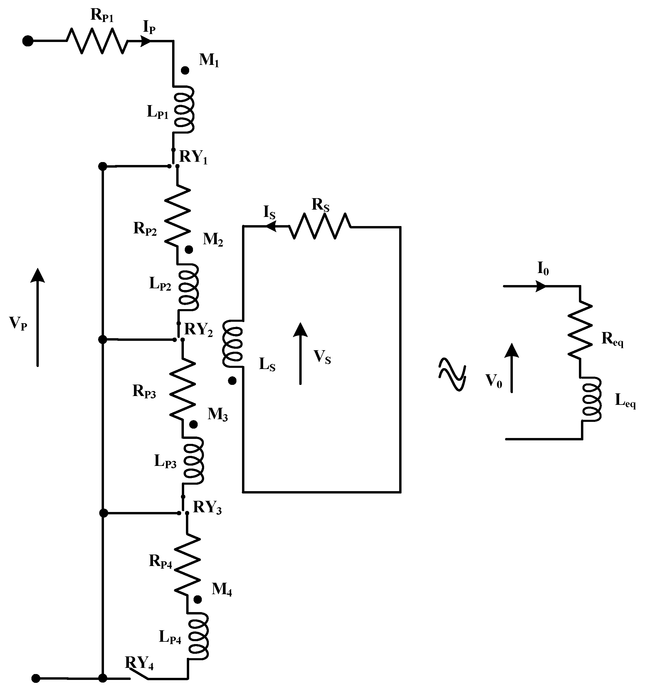
Figure 1 shows the equivalent circuit modeling of the proposed multi-tapped IH with corresponding series resistance (R
eq) and inductance (L
eq).
For the coil tapped at 25% of the total coil size and the load (pan/vessel) diameter corresponding to this coil size, the primary coil’s self-inductance is
LP1, the transformer’s mutual inductance is
M1, while the load resistance is
RS and the coil resistance is
RP1.
IP represents the work coil current and
IS indicates the load current. The IH load equivalent circuit’s KVL voltage equation is provided by Equations (1) and (2), whereas Equation (3) provides the expression for angular frequency.
where
ωs represents the angular frequency, whereas
FS represents the switching frequency. By solving Equations (1) and (2) and by breaking down the real and imaginary components,
Req and
Leq are obtained by Equations (4) and (5), respectively.
The electrical time constant can generally be defined by Equation (6):
Equation (7) indicates the mutual inductance
M:
The load-equivalent impedance is given by Equation (8).
where
fr is the resonant frequency that is expressed by Equation (9).
The output current at the load side is given by Equation (10).
The load output power can be obtained by using Equation (11):
where
IO refers to the rms output current.
Equation (12) represents the quality factor of the coil:
where
ωr is the angular resonant frequency that is given as
2πfrDue to the winding active resistance and the reduced load, losses are present in the circuit. In such a case, Equation (9) can be modified as Equation (13) [
26].
where
ωo is the lossless natural angular frequency and α is the damping attenuation in units of nepers per second. The damping attenuation can be expressed by Equation (14).
The modeling for the 50%, 75%, and 100% segments made in the coils are similar to the above procedure. For each segment, the pans with the corresponding diameter were selected.
2.2. Circuit Description
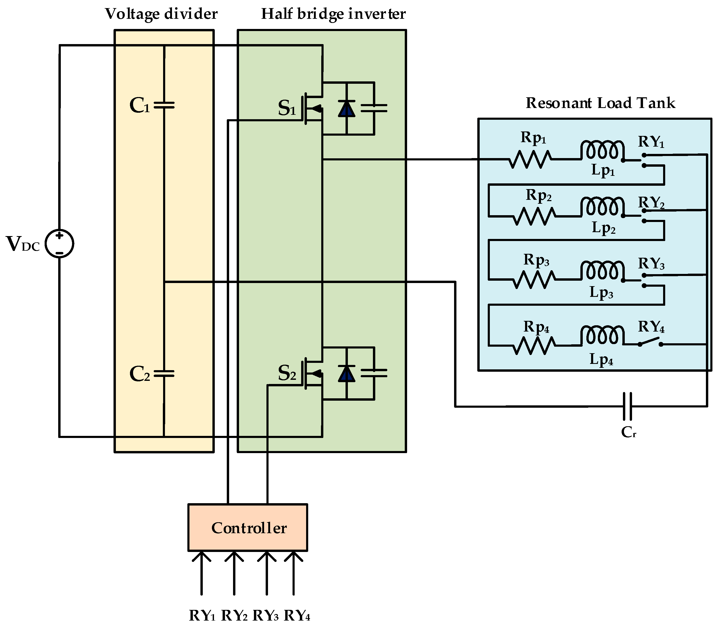
The circuit diagram of the single-coil multi-tapped DC-AC half-bridge series resonant inverter is shown in
Figure 2. It comprises two MOSFET switches, namely S
1 and S
2, which are used to alter the DC input to a high-frequency AC output. These switches are connected to the controller, which provides the switching frequency depending on the relays selected. Capacitors C
1 and C
2 act as the voltage dividers. The heating coil is multi-tapped at three different places and each segment is connected to the separate relays, namely RY
1, RY
2, RY
3, and RY
4. The modeling of the IH load is conducted with four series resistances R
p1, R
p2, R
p3, and R
p4; four inductances L
p1, L
p2, L
p3, and L
p4; the resonant capacitor C
r. L
p1 refers to the inductance of the 25% of the IH coil, whereas L
p2, L
p3, and L
p4 are the inductances of 50%, 75%, and 100% of the IH coil, respectively. Similarly, R
p1, R
p2, R
p3, and R
p4 are the equivalent inductances of the 25%, 50%, 75%, and 100% of the IH coil, respectively. Altogether, this series-connected RLC is called the series resonant load tank.
The present induction cooking unit (induction stove) possesses an induction coil unit, which is powered by a power electronic interface and the cooking vessel is kept on the surface of the unit (isolated from primary). Here, the consumption of electric power is immaterial of the size of the vessel. Indeed, the whole of the heating coil is excited even for a relatively smaller vessel, which incurs losses. Moreover, the induction heating unit with individual coils having different sizes of coils powered by the individual power electronic interfaces has drawbacks such as larger size, individual control unit, and higher cost. This research on the IH system is very amenable for developing economies, where the cost of the IH is not increased with more power saving.
2.3. Modes of Operation
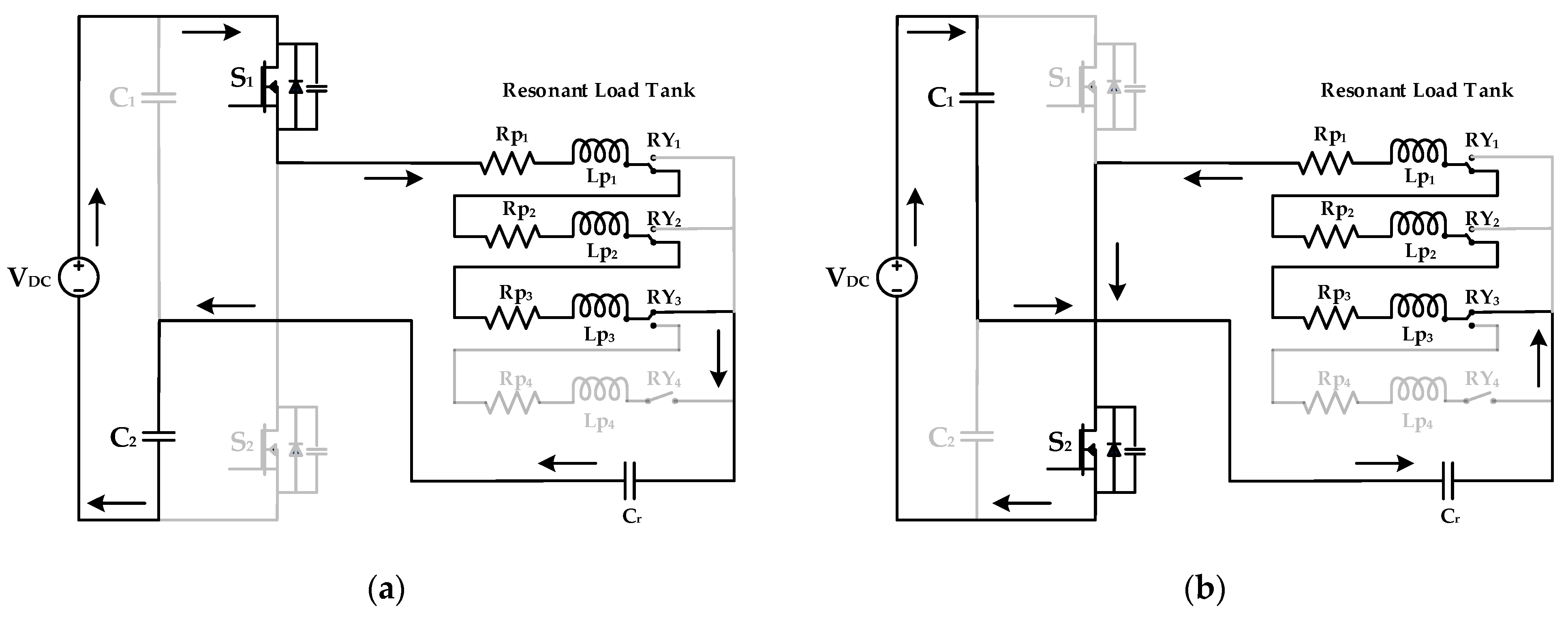
Based on the size of the vessel to be heated, the mode of operation can be selected manually by pressing the corresponding relay switch. The output voltage and the output current are expressed as V0 and I0, respectively. The induction coil is multi-tapped at 25%, 50%, 75%, and 100% of the coil and the vessel is selected depending on the area of the coil.
2.3.1. Mode 1: 25% Tapping of IH Coil
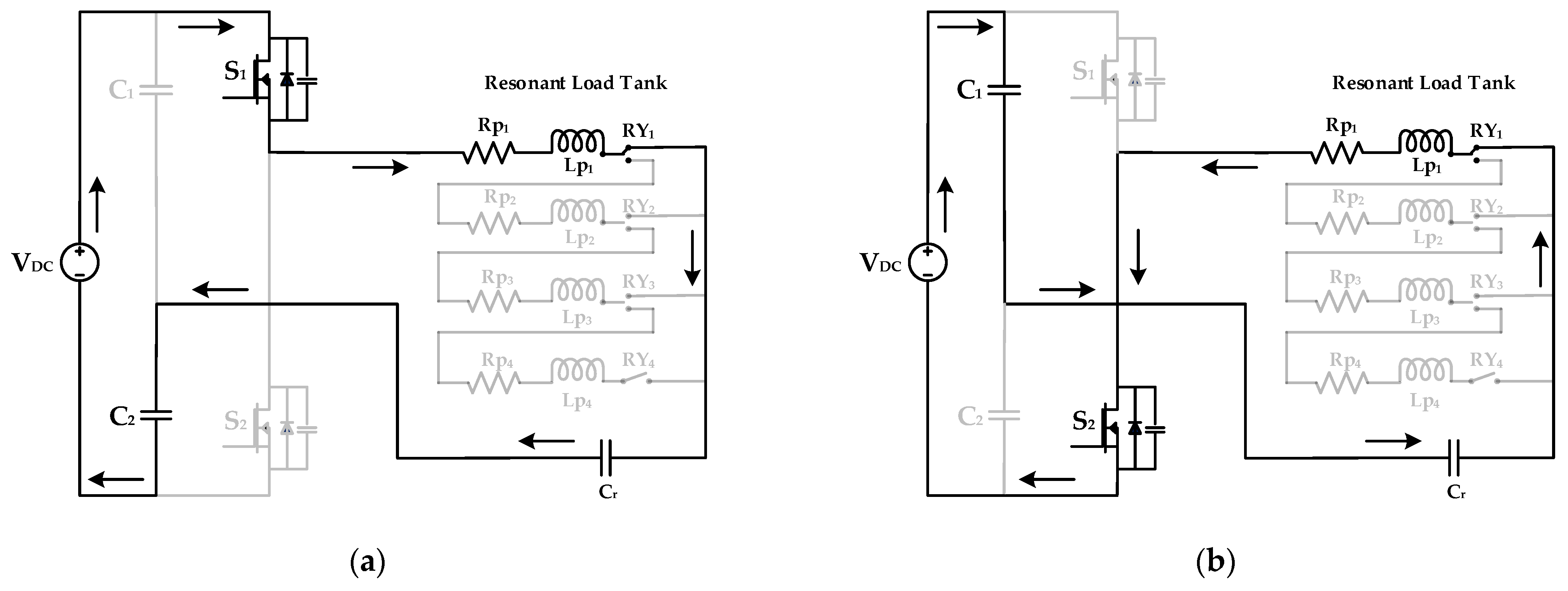
In mode 1, the load is selected as per 25% of the area of the induction coil. For this operation, RY
1 is switched on and the corresponding coil of L
p1 is energized. The switching frequency corresponding to relay RY
1 is fed to the switches with the help of the controller. Switch S
1 is turned on and the flow of current is from S
1, R
p1, L
p1, RY
1, C
r, and C
2. The remaining coils do not become energized. Then, switch S
2 is turned on and the current flows in the direction of C
1, C
r, RY
1, L
p1, R
p1, and S
2. This operation is shown in
Figure 3.
2.3.2. Mode 2: 50% Tapping of IH Coil
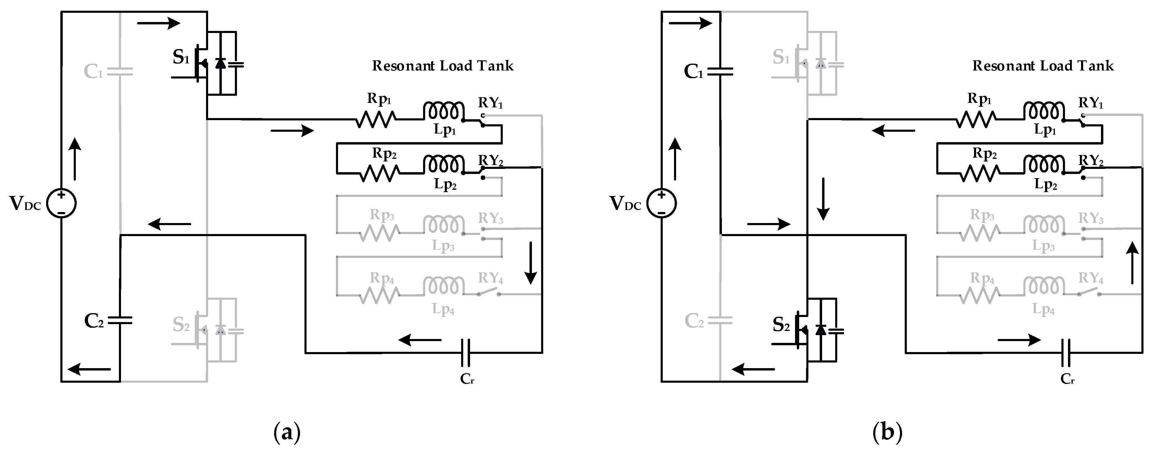
The load selected for mode 2 operation has a size equal to 50% of the IH coil. The relay switch of RY
2 is selected for this mode. The controller operates the switches with the respective frequency. S
1 is turned on and the current flows in the direction of S
1, R
p1, L
p1, RY
1, R
p2, L
p2, RY
2, C
r, and C
2. The remaining relays are in the off condition. When switch S
2 is turned on, the direction of current flow is from C
1, C
r, RY
2, L
p2, R
p2, RY
1, L
p1, R
p1, and S
2. This operation is shown in
Figure 4.
2.3.3. Mode 3: 75% Tapping of IH Coil
In mode 3 operation, the load selected covers 75% of the area of the IH coil and the RY
3 relay switch is pressed to activate 75% of the IH coil. The corresponding switching frequency is fed to the switches by the controller. The direction of current flow is from S
1, R
p1, L
p1, RY
1, R
p2, L
p2, RY
2, R
p3, L
p3, RY
3, C
r, and C
2 when switch S
1 is turned on. Other coils remain unenergized for this whole process. The current flow for turning on switch S
2 would be from C
1, C
r, RY
3, L
p3, R
p3, RY
2, L
p2, R
p2, RY
1, L
p1, R
p1, and S
2. This operation is shown in
Figure 5.
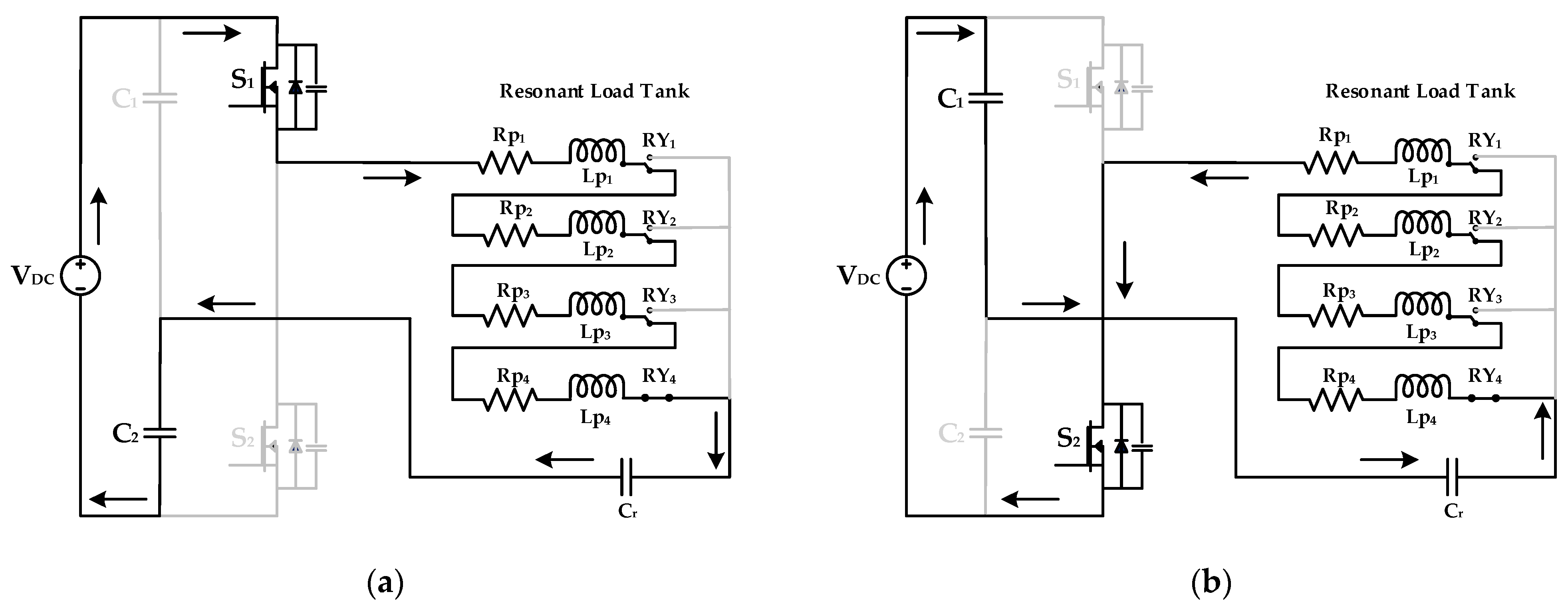
2.3.4. Mode 4: 100% of IH Coil
The operation of mode 4 is shown in
Figure 6. A percentage of 100% of the IH coil is energized in this mode, which is achieved by selecting relay RY
4. The load selected for Mode 4 needs to cover the full area of the IH coil and its matching switching frequency is given to switches S
1 and S
2 with the help of a controller. The current flow is in the direction of S
1, R
p1, L
p1, RY
1, R
p2, L
p2, RY
2, R
p3, L
p3, RY
3, R
p4, L
p4, RY
4, C
r, and C
2 when switch S
1 is turned on. When switch S
2 is turned on, the flow of current is from C
1, C
r, RY
4, L
p4, R
p4, RY
3, L
p3, R
p3, RY
2, L
p2, R
p2, RY
1, L
p1, R
p1, and S
2.
2.4. Output Power Control Using PDM Technique
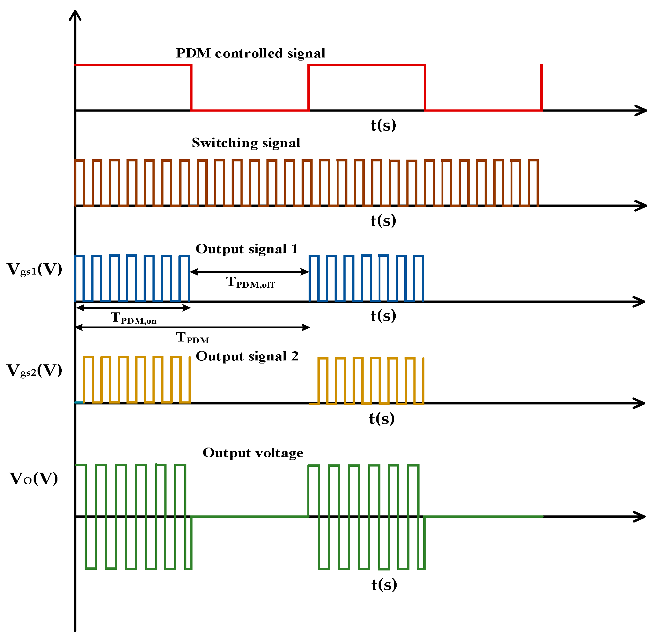
The essential temperature can be maintained in an IH system by regulating the output power. The PDM-based pulse masking control technique is devised to accomplish the task. In the inverter, ZVS is achieved when the switching frequency is a little higher than the resonant frequency. As a result, the PDM control method based on pulse masking is devised. In this method, the resonant pulses density is altered, rendering the output power needed. ZVS is realized throughout the spectrum of load changes as the inverter’s resonance frequency is kept constant. The PDM pulse generation is shown in
Figure 7. A low-frequency pulse with time period
TPDM is selected to alter the density of switching pulses. A logical operation must be carried out in such a way that the switching pulses with a high frequency are permitted to reach the inverter during the low-frequency signal’s on period (
TPDM,on). Pulses are muted for the period of its off period (
TPDM,off).
The amplitude of the instantaneous current output is expressed by Equation (15).
where
Imax is the maximum value of the output current.
The power output can be changed by altering
Ton. During the off time, the energy stored within the resonating parts tends to freewheel within the IH load. The
PDM duty cycle is given by Equation (16).
Duty cycle, modulation index, and pulse density are the terms used to describe
DPDM. With
PDM, the relation between rated power (
Pr) and output power
PO is expressed by Equation (17):
The maximum output power is reached when the value of DPDM is 1, which means that both TPDMon and TPDM have the same value. Controlling DPDM with a constant switching frequency allows for the variation in the output power, ensuring a soft switching for a broad range of variations in the load.
2.5. Analysis of Switching Losses
Conduction and switching losses are the two types of losses connected with the semi-conductor switches. The system’s resonant operation can be detected with minimal switching losses. Using the formulas in this section, the conduction and switching losses of the power semiconductor switches can be determined. Switching losses are divided into two categories: turn on and turn off losses. In MOSFETs, the total power loss (
PTL) is given by Equation (18).
Pcond refers to the MOSFET’s conduction power loss, while
Pswitch refers to the switching power loss of MOSFET in the circuit. The term
Pcond is calculated by using Equation (19).
Rs(on) represents the switch on state resistance and
Isw refers to the current flows through the switch. The switching loss of MOSFET
Pswitch is written by Equation (20):
where
Vsw refers to the switch voltage in the on state and
Toff is the switch off time period. Losses related with semiconductor switches can be computed using the preceding formulae.
3. Experimental and Simulation Results
3.1. Simulation and Test Rig Development
The multi-tapped induction heating system is set to be operated at four different frequencies depending upon the size of the load and the coil to be heated. In MATLAB/Simulink software, the proposed system with the PDM control is simulated according to the design specifications listed in
Table 1.
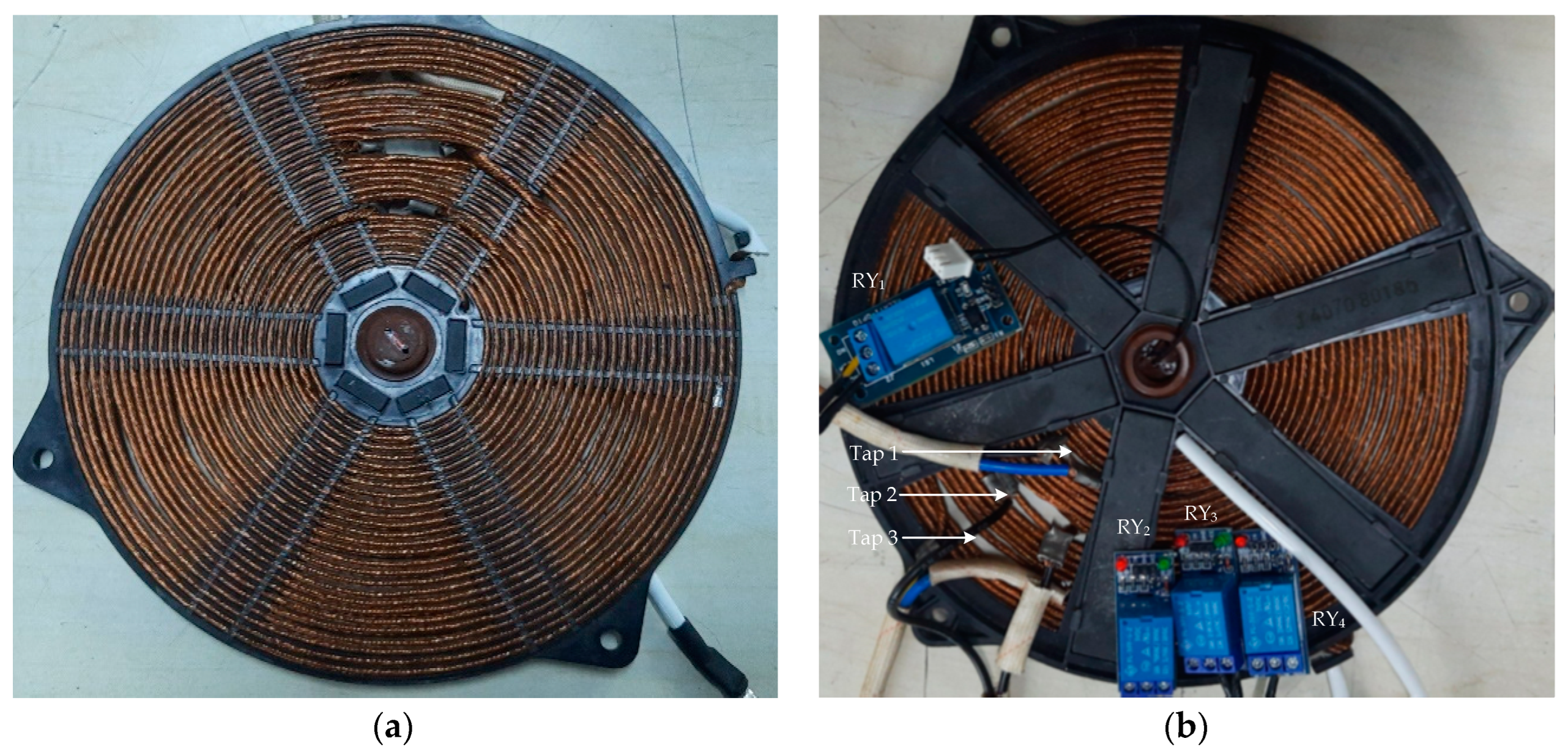
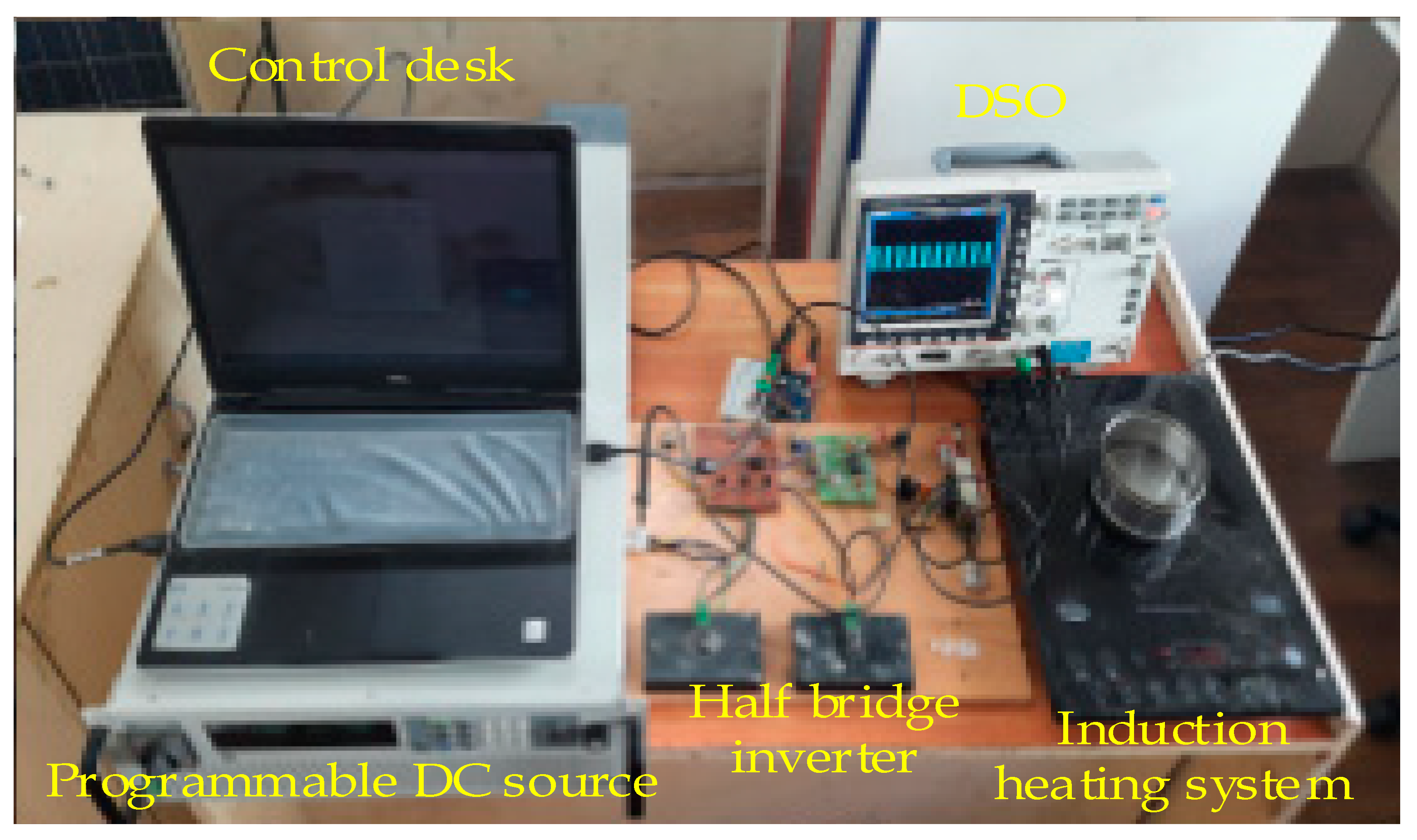
A PIC16F877A controller was used to validate the control system, which is driven by a FAN7392N driver IC. Two IRFP4668MOSFET power switches rated at 200 V and 130 A make up the main circuit. The waveforms were recorded using a GW Instek GDS-2202A digital storage oscilloscope. The thermal image of the load was captured using a sophisticated thermal imager Fluke Ti401. The top and bottom views of the multi-tapped induction coil with relays used in the proposed system is shown in
Figure 8 and the experimental setup for the proposed system is shown in
Figure 9.
3.2. Multi-Tapped Induction Heating System with PDM-Based Power Control
To alter the temperature according to the load requirement in an IH system, a precise power control technique is necessary. The PDM-based control technique is used for controlling the power output in this research work. In order to prevent the acoustic noise, the frequency of the DPDM in this investigation is set to 10 Hz [
27]. Four different test cases as mentioned above are considered for testing the system, and for all the test cases, the output power can be varied by changing the duty cycle of the PDM from 25% to 100%, which is verified using the simulations as well as the experiments.
3.2.1. Mode 1 with Different PDM
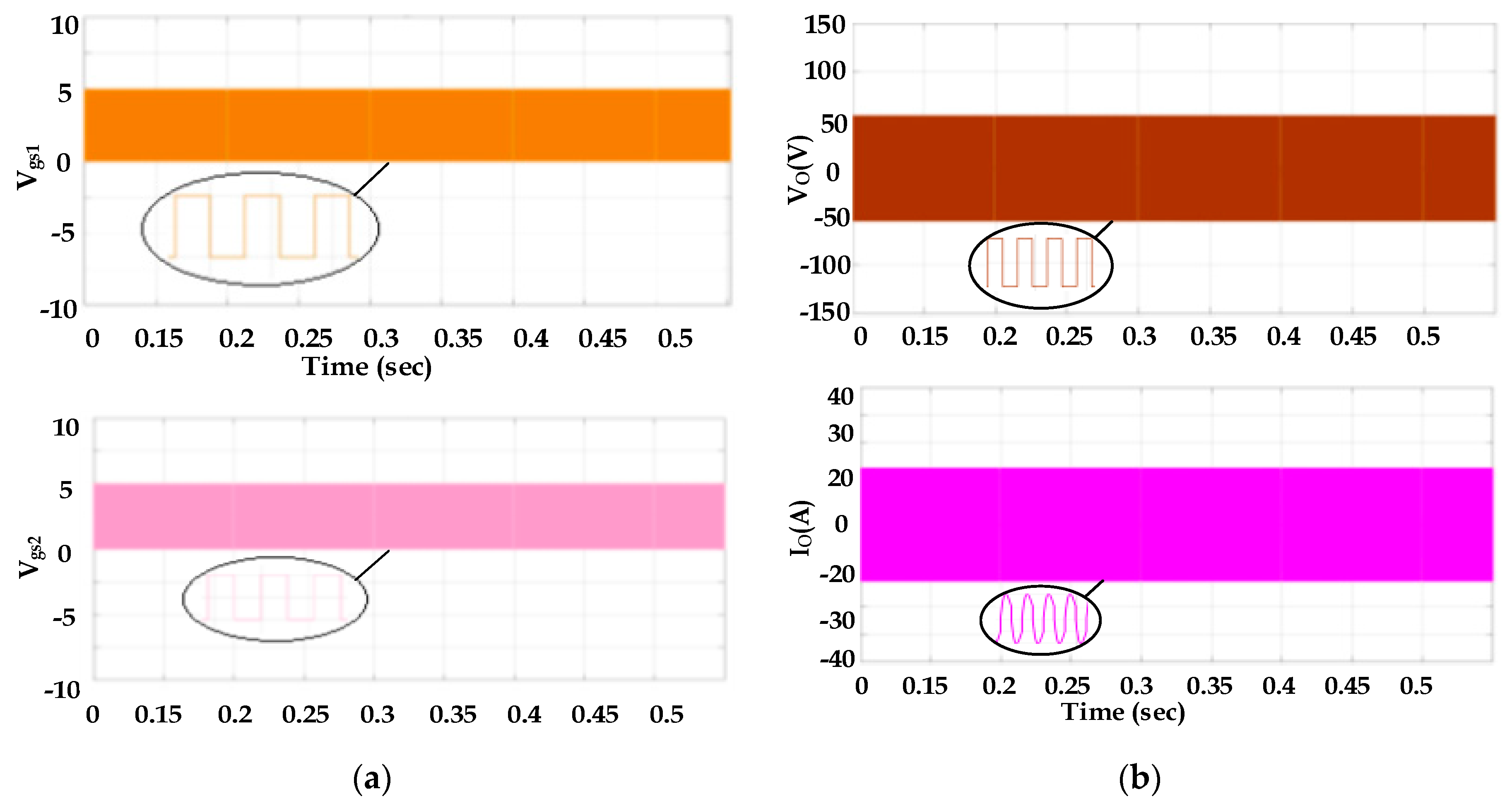
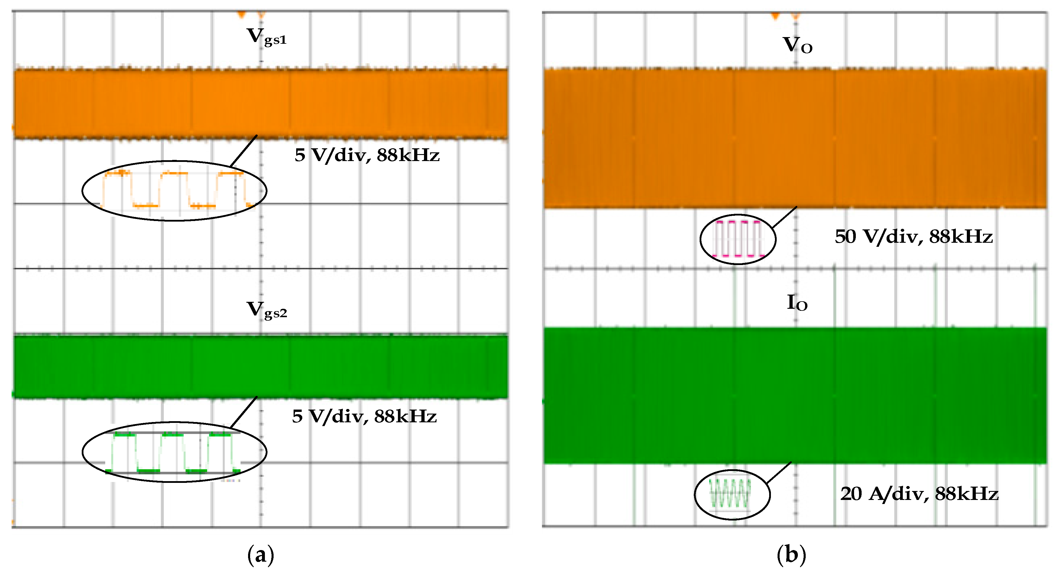
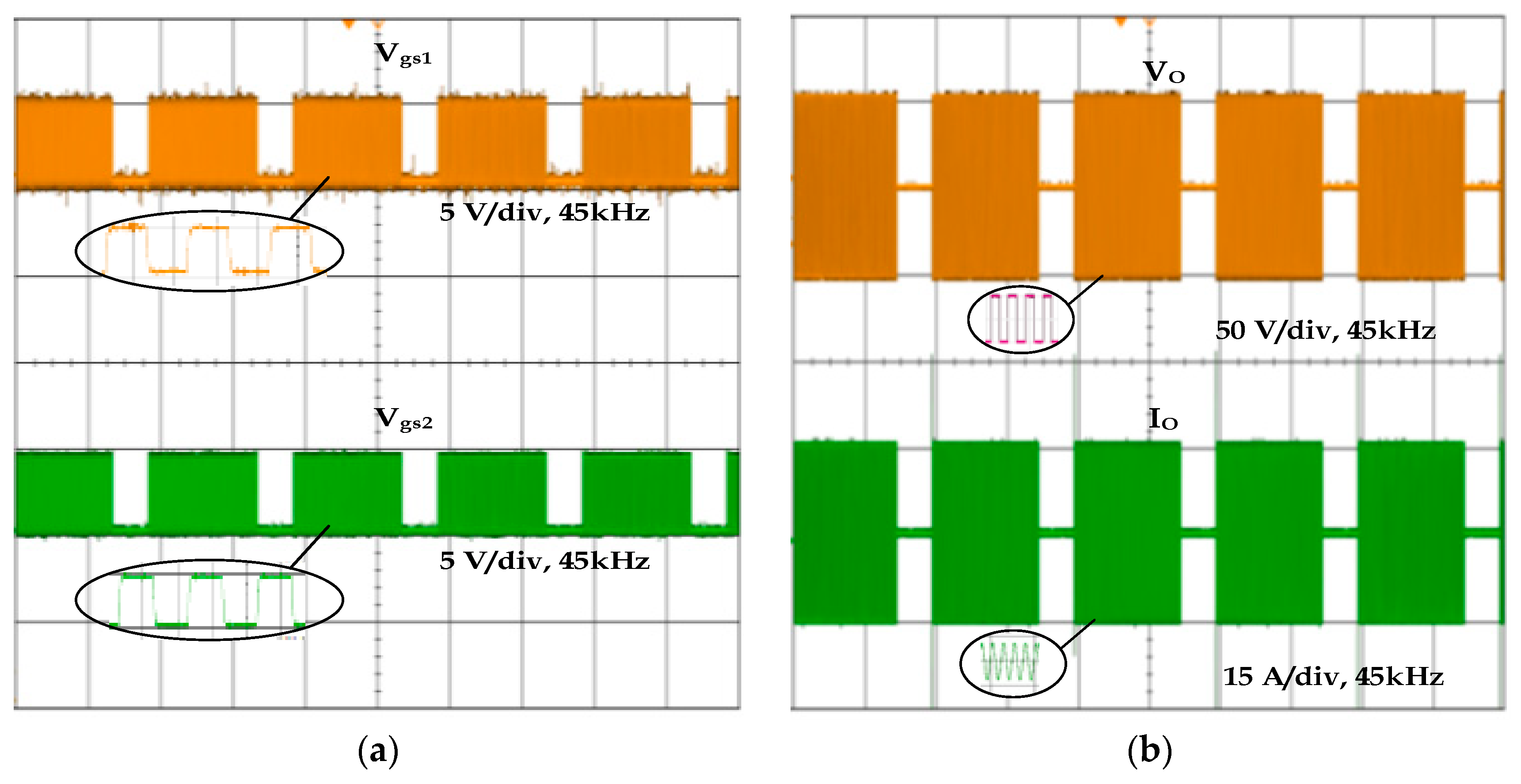
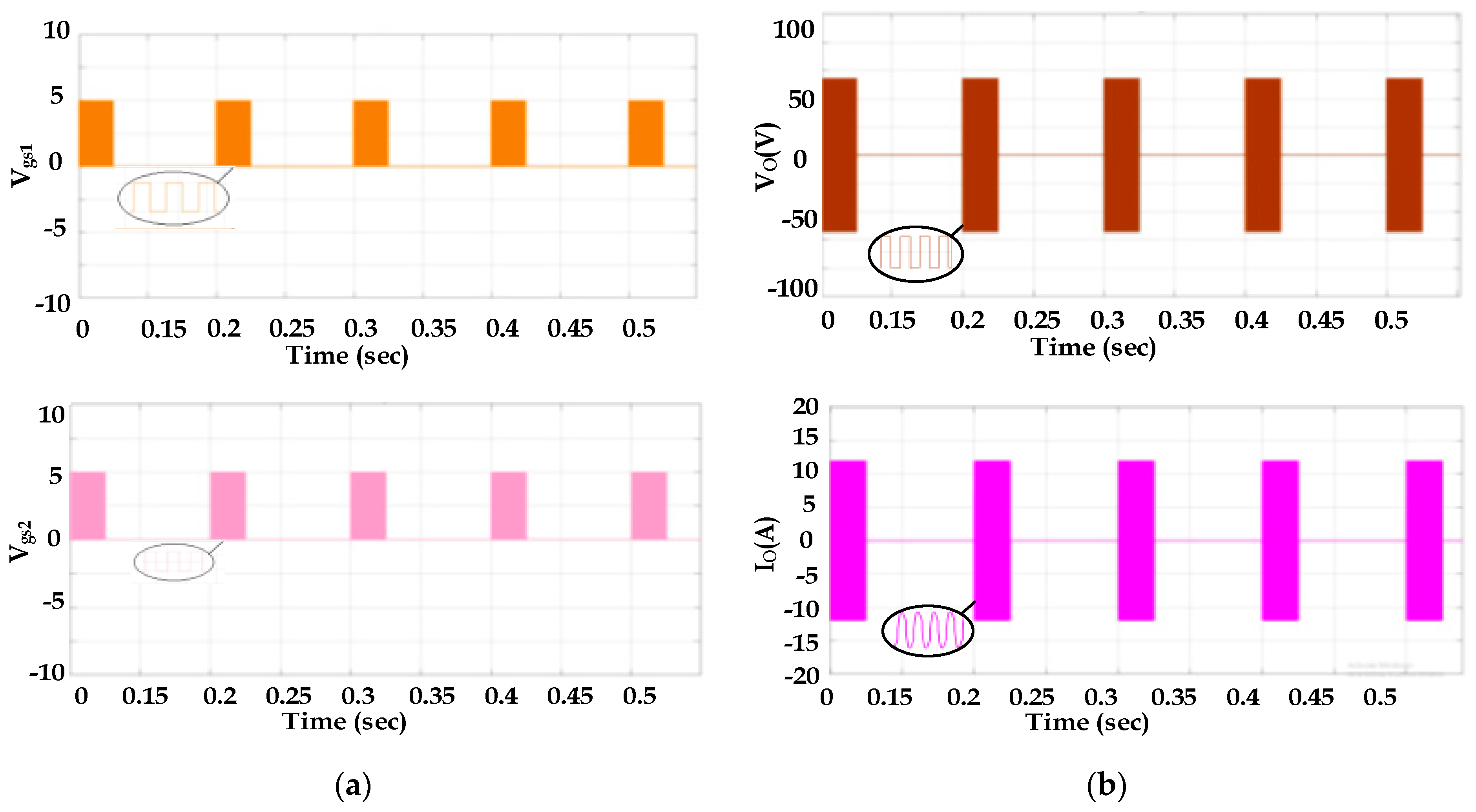
Switching pulses Vgs1 and Vgs2 applied to switches S1 and S2 for mode 1 at 100% PDM are simulated. This is verified experimentally, which is shown in
Figure 10a and
Figure 11a along with the expanded views. The output voltage and current waveforms related to this mode with the expanded view for the simulation and experiment are illustrated in
Figure 10b and
Figure 11b. For Mode 1, the rated power is 850 W with an equivalent resistance of 2.9 Ω. The diameter of the pan selected for Mode 1 is 45 mm. The simulation and experimental results agree with each other.
The half-bridge inverter is operated at 75% of the PDM duty cycle in Mode 1 and the developed net power output is around 634 W. I0rms2Req is used to calculate the load’s output power, where I0rms is the output current’s rms value and Req is the equivalent resistance of the load. The input power is calculated by multiplying the input DC voltage by the inverter’s average input current. For 50% of the PDM duty cycle, the net output power is 423 W. As for 25% of the duty cycle, the net power further reduces to 211 W. From the above details, it is inferred that the output power changes depending upon the duty cycle of the PDM, as mentioned in Equation (19). For all the duty cycles, the magnitude of voltage and current remains the same.
3.2.2. Mode 2 with Different PDMs
For Mode 2 at 75% of the PDM duty cycle, the simulation and experimental waveforms of the pulses applied to the switches are illustrated in
Figure 12a and
Figure 13a. In addition, the output voltage and current waveforms from the simulation, as well as the experiment, are shown in
Figure 12b and
Figure 13b. The net power output of 75% of the PDM duty cycle is 472 W. The PDM duty cycles of 100%, 50%, and 25% for Mode 2 produce the output power of 629 W, 315 W, and 157 W, respectively. By reducing the duty cycle of the PDM, the output power of the system can also be reduced based on the user’s requirements. The output power of the system can be varied without altering the frequency of the switching pulse. In this mode, the diameter of the pan selected is about 90 mm. The rated power of Mode 2 is the output power of 100% of the PDM duty cycle.
3.2.3. Mode 3 with Different PDMs
The rated power for Mode 3 operation is 545 W, which is obtained at 100% of the PDM duty cycle. The net output power of 75%, 50%, and 25% of the duty cycles are 409 W, 272 W, and 136 W, respectively. The variation in the output power can be achieved by changing the PDM duty cycle with the constant switching frequency. The pan diameter for Mode 3 is 135 mm. The simulation and experimental results follow each other.
3.2.4. Mode 4 with Different PDMs
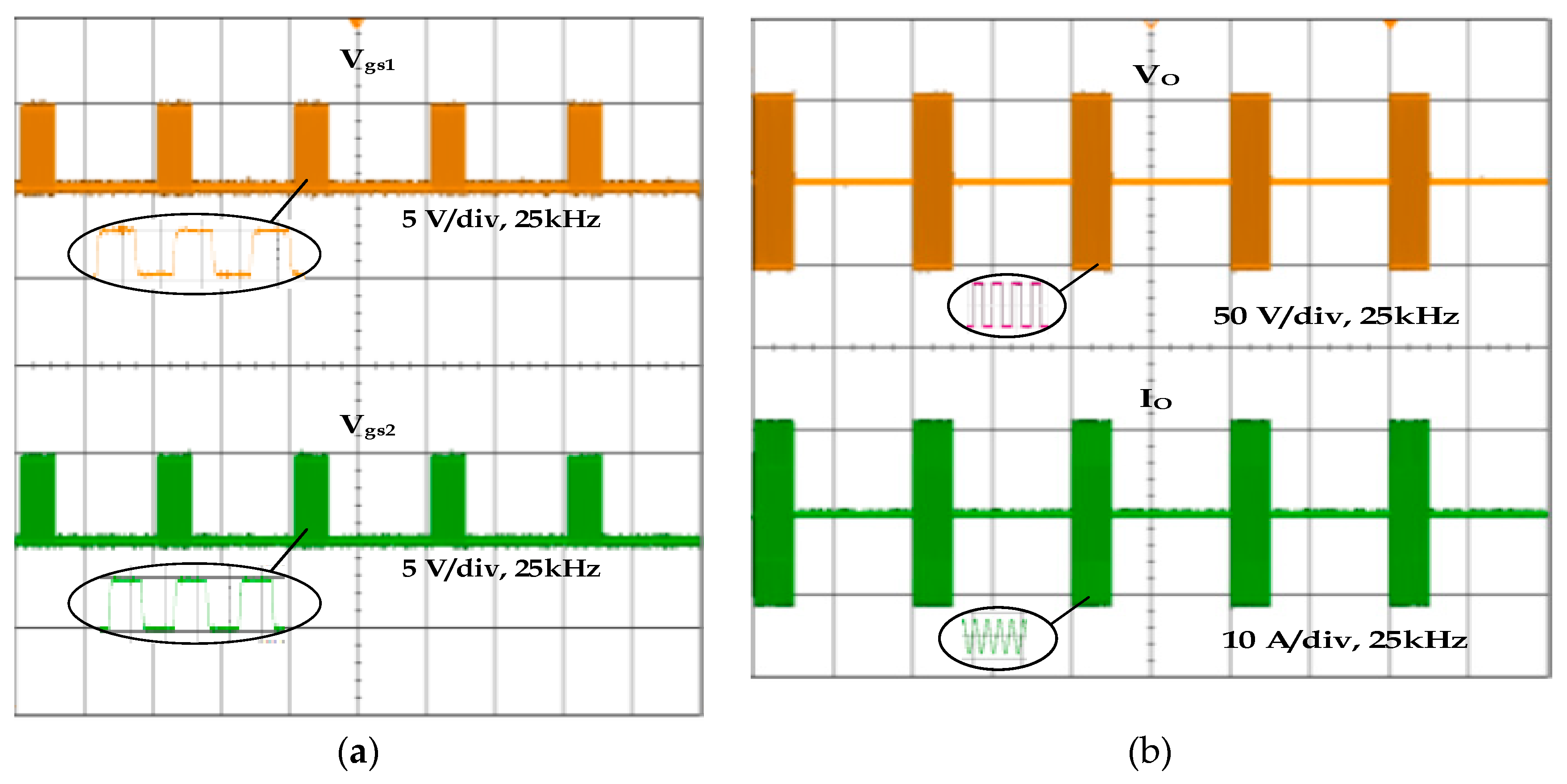
The simulation and experimental results for switching pulses 1 and 2 for Mode 4 are shown in
Figure 14a and
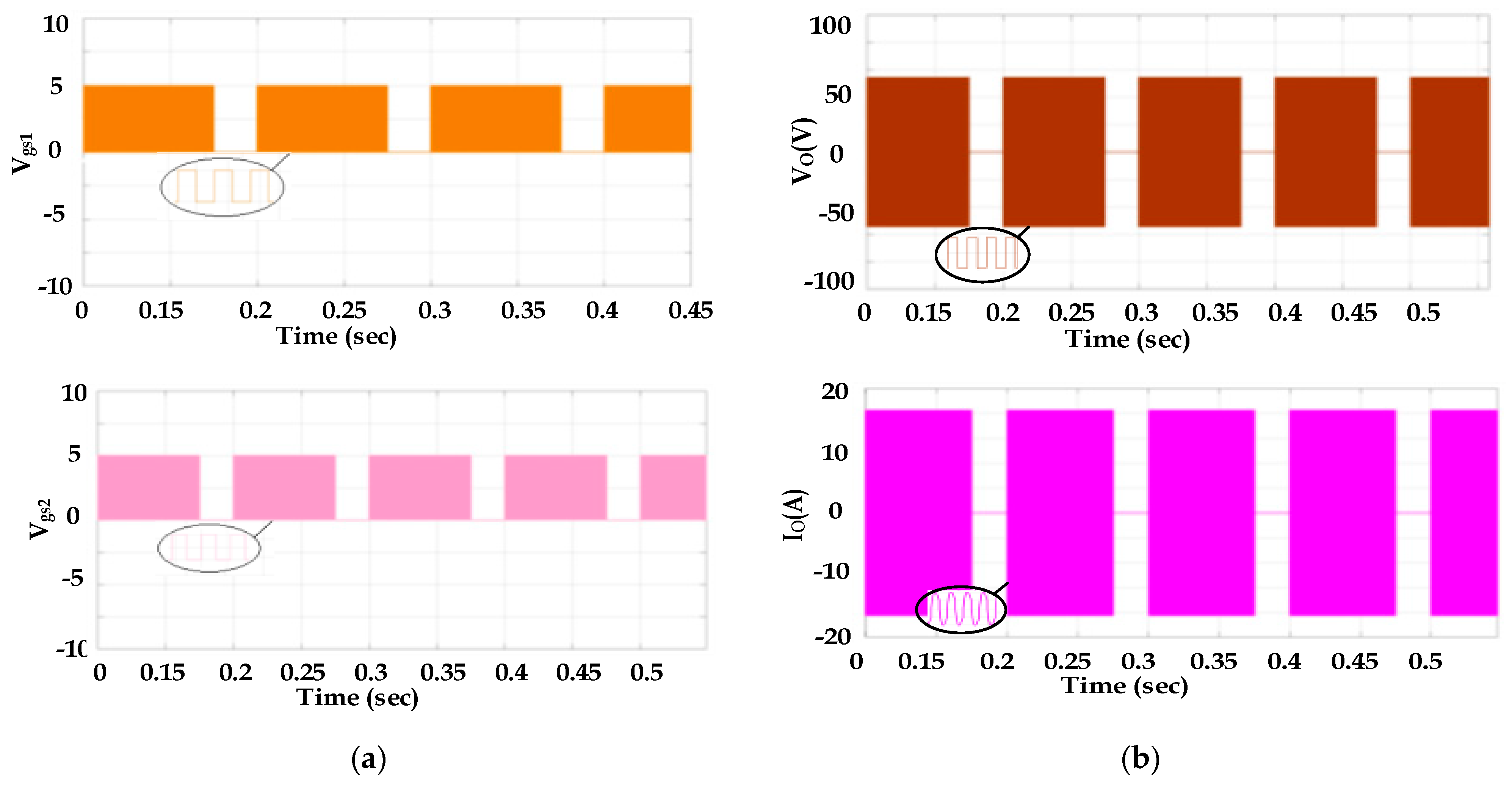
Figure 15a. The simulation and experimental results for output voltage and current waveforms of 25% of the PDM duty cycle for Mode 4 are shown in
Figure 14b and
Figure 15b. The net output power for this case is 122 W. For the remaining PDM duty cycles such as 100%, 75%, and 50%, the output powers are 490 W, 368 W, and 245 W, respectively. From this, it is inferred that by changing the PDM duty cycle, the output power of the induction heating system can be controlled well. The diameter of the pan used in Mode 4 is 180 mm. The simulation results agree well with the experimental results.
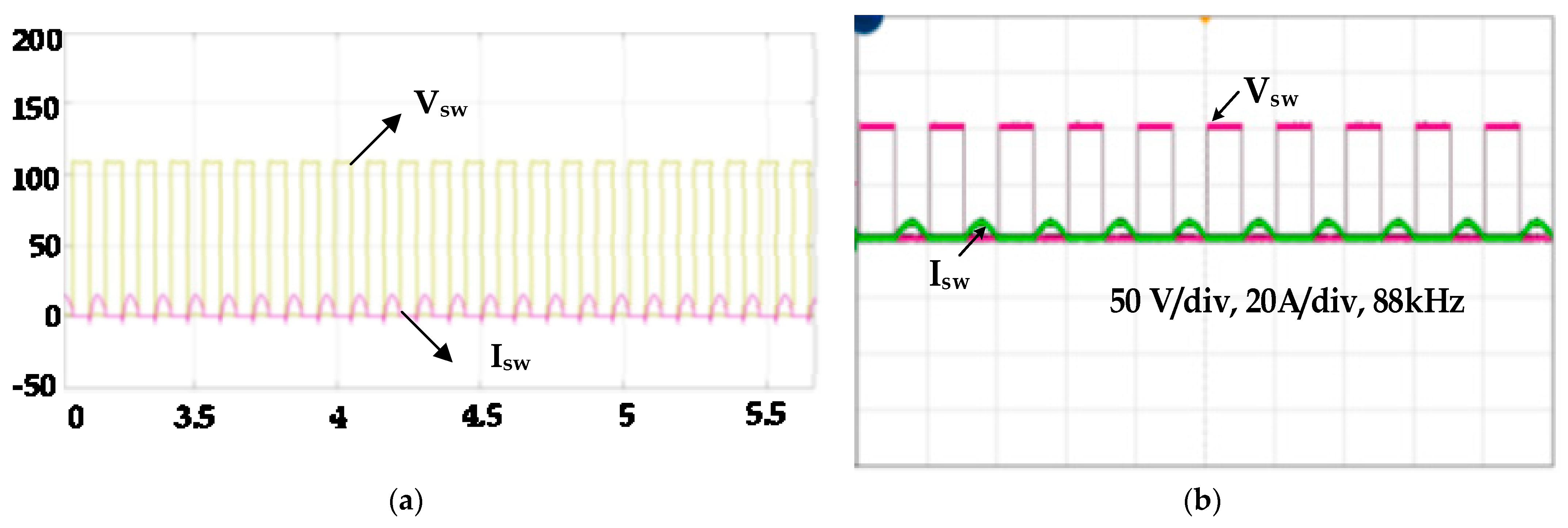
3.2.5. Soft Switching
At various load power levels, the soft switching is achieved when the switching frequency is kept constant. At the soft switching condition, the switching losses are eliminated, which leads to the ZVS, whereas in hard switching, there is a presence of switching losses. This is the major advantage of using the PDM technique in the induction heating system operated by a series resonant converter. The simulation and experimental results for switching voltage and current are shown in
Figure 16.
3.2.6. System Performance (Heating Time, Energy Loss, and Efficiency)
The vessels of different sizes are heated using the corresponding area of the induction coil and its thermal images are captured using a Fluke Ti401. The thermal images for the four different modes are shown in
Figure 17.
Electrical devices facilitate the transfer of electrical currents from one circuit to another. During this energy transfer, a portion of the energy is released as heat. Copper loss is referred to as this energy loss as the heat emitted by the gadget is not utilized and just disappears into the air. Copper loss is an undesirable but currently unavoidable occurrence. This heat loss causes a negligible amount of power loss in the gadget. The copper loss for the various modes is identified through Equation (21).
The copper losses associated with Mode 1, Mode 2, Mode 3, and Mode 4 are 6.5 W, 14.6 W, 21.8 W, and 24.7 W respectively. This loss will change when the load changes. If there were no multi-tapping, the copper losses associated with different vessels would be around 24.7 W.
Table 2 shows the efficiency and output power for different modes at different PDM ranges.
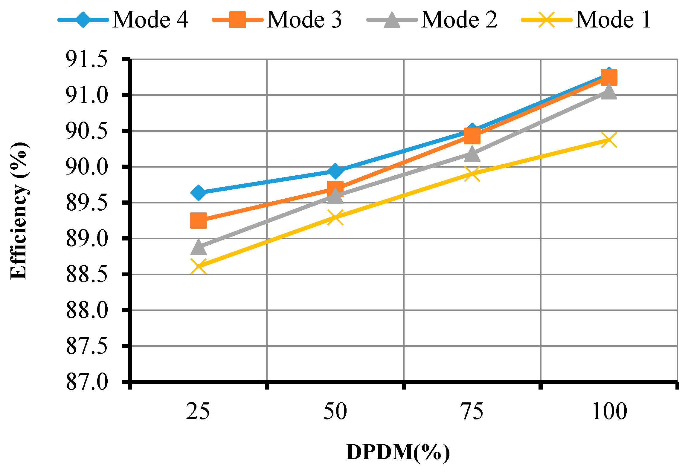
The efficiency of the different modes of the proposed technique is shown in
Figure 18. Mode 4 has a high efficiency of 91.3% and Mode 1 holds the low efficiency of 90.4% among all the other modes for 100% of the PDM duty cycle. From this result, it is inferred that a change in the duty cycle can be used to control the output power. An increase in the duty cycle from 25% to 100% increases the output power as well as the efficiency. For each mode, the efficiency reaches the maximum at 100% of the PDM duty cycle.
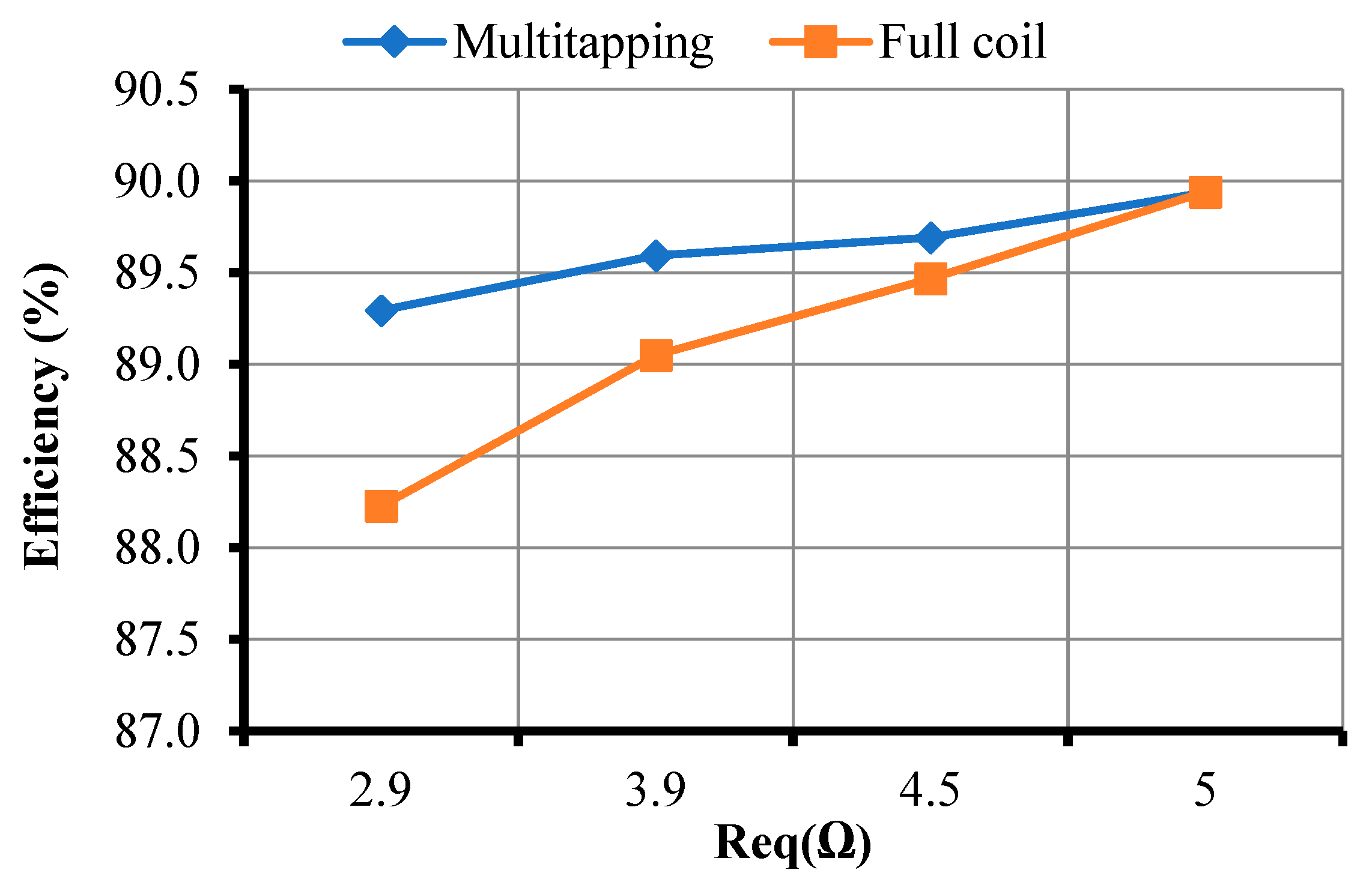
The different sized vessels used in the multi-tapping system are heated in the induction system without multi-tapping. Its efficiency is compared with the results of the multi-tapping system and is shown in
Figure 19. It is inferred that the efficiency of the system decreases when heating the vessel with different sizes in the full coil compared to the multi-tapping system. The system with multi-tapping provides higher efficiency compared to the one without multi-tapping.
4. Discussions
The efficiency of the multi-tapping system at four different segments was analyzed for various duty cycles of the PDM. In Mode 1 operation, the experiments were performed for four different duty cycles such as 25%, 50%, 75%, and 100% and obtained the corresponding efficiency values of 88.61%, 89.29%, 89.9%, and 90.37%. In Mode 2 operations, for the four different above-mentioned duty cycles, the corresponding efficiency values were 88.88%, 89.59%, 90.18%, and 91.05%. The estimated efficiency values for different duty cycles for Mode 3 were 89.25%, 89.69%, 90.43%, and 91.24%, respectively. For the fourth mode, the obtained efficiency values for the four different duty cycles were 89.64%, 89.94%, 90.5%, and 91.28%, respectively. Mode 4 with 100% PDM provided better efficiency when compared to all other modes with a value of 91.3%. The efficiency also decreased with the decrease in the PDM duty cycle and with a reduction in the coil tapping. Mode 1 provided the lowest efficiency when compared to the other modes for all the duty cycles of the PDM, whereas the efficiency of the subsequent modes increased when compared to the previous modes.
Then, the efficiency of the multi-tapping system was compared with the system without multi-tapping. For the four different equivalent resistance values such as 2.9 Ω, 3.9 Ω, 4.5 Ω, and 5 Ω, the efficiency values obtained for the multi-tapping system were in the order of 89.29%, 89.59%, 89.69%, and 89.94%. The estimated efficiency values for the same set of equivalent resistances for the system without multi-tapping were 88.23%, 89.05%, 89.47%, and 89.94%, respectively. From the above data, it is proven that the multi-tapping system provides better results when compared to the system without multi-tapping for different load conditions. The efficiency remains the same in both cases for the 5 Ω equivalent resistance, whereas, for the other equivalent resistance values, the full-coil system efficiency reduces when compared with the proposed system. By varying load sizes in multi-tapping, the power losses can be reduced when compared with the system without multi-tapping. However, a slightly complex control system is the major limitation for the proposed system.
The following benefits of the proposed method can be deduced from simulation and experimental results: a simple setup, a large-load power control range, lower switching losses, improved efficiency, less energy consumption, and reduced strain in the induction coil.
5. Conclusions
In this research work, a half-bridge series resonant inverter with a multi-tapping system for cooking applications is proposed for different load sizes. The output power for each mode can be controlled by using the PDM control technique and by varying its duty cycle. The inverter’s design and analysis for IH applications are presented. The proposed scheme’s principle is thoroughly detailed with simulation results used to verify the proposed method’s performance. A prototype module is used to test the suggested method experimentally. The temperatures in all the modes are measured using the thermal imager. The outputs of the research work are summarized as follows:
Multi-tapping of the induction coil is developed for heating different sizes of the load.
The power output is controlled from 25% to 100% of the rated power for all the modes.
Due to the constant switching frequency, soft switching is achieved in a wide range of power variations for all the modes.
For each mode, the maximum efficiency is attained at 100% of the PDM duty cycle and Mode 4 has the highest efficiency of 91.3%.
For the smallest load, the proposed system provides the efficiency of 89.29%, whereas the system without multi-tapping gives the efficiency of 88.23%, which is lower compared to that of the proposed system. The efficiency of the system increases with an increase in the equivalent resistance.
This research work can be further extended to select the modes automatically depending on the size of the load placed in the system.
Author Contributions
All authors had an equal contribution in preparing and finalizing the manuscript. Conceptualization: S.R.R., C.S.B. and S.R., methodology, S.R.R., C.S.B. and S.R.; software: S.R.R., C.S.B. and S.R.; validation: S.R.R., C.S.B., S.R., M.A., J.H. and M.S.; formal analysis: S.R.R., C.S.B., S.R., M.A., J.H. and M.S.; investigation: S.R.R., C.S.B. and S.R.; resources: C.S.B. and S.R.; data curation: S.R.R., C.S.B. and S.R.; writing—original draft preparation: S.R.R., C.S.B. and S.R., M.A., J.H. and M.S.; writing—review and editing: S.R.R., C.S.B., S.R., M.A., J.H. and M.S.; visualization: C.S.B., S.R., M.A., J.H. and M.S.; supervision: C.S.B., S.R., M.A., J.H. and M.S. All authors have read and agreed to the submitted version of the manuscript.
Funding
This research received no external funding.
Institutional Review Board Statement
Not applicable.
Informed Consent Statement
Not applicable.
Data Availability Statement
The data presented in this study are available in article.
Acknowledgments
The authors would like to thank the team of Manchester Met University for their support for this research work and preparing the manuscript.
Conflicts of Interest
The authors declare no conflict of interest.
References
- Lucia, O.; Maussion, P.; Dede, E.J.; Burdio, J.M. Induction Heating Technology and Its Applications: Past Developments, Current Technology, and Future Challenges. IEEE Trans. Ind. Electron. 2014, 61, 2509–2520. [Google Scholar] [CrossRef]
- Hurley, W.; Kassakian, J. Induction heating of circular ferromagnetic plates. IEEE Trans. Magn. 1979, 15, 1174–1181. [Google Scholar] [CrossRef]
- Plumed, E.; Lope, I.; Acero, J. Induction Heating Adaptation of a Different-Sized Load With Matching Secondary Inductor to Achieve Uniform Heating and Enhance Vertical Displacement. IEEE Trans. Power Electron. 2021, 36, 6929–6942. [Google Scholar] [CrossRef]
- Ngoc, H.P.; Fujita, H.; Ozaki, K.; Uchida, N. Phase Angle Control of High-Frequency Resonant Currents in a Multiple Inverter System for Zone-Control Induction Heating. IEEE Trans. Power Electron. 2011, 26, 3357–3366. [Google Scholar] [CrossRef]
- Pham, H.N.; Fujita, H.; Ozaki, K.; Uchida, N. Estimating Method of Heat Distribution Using 3-D Resistance Matrix for Zone-Control Induction Heating Systems. IEEE Trans. Power Electron. 2012, 27, 3374–3382. [Google Scholar] [CrossRef]
- Lucía, Ó.; Burdío, J.M.; Barragán, L.A.; Acero, J.; Millán, I. Series-Resonant Multiinverter for Multiple Induction Heaters. IEEE Trans. Power Electron. 2010, 25, 2860–2868. [Google Scholar] [CrossRef]
- Rodriguez, J.I.; Leeb, S.B. Nonresonant and Resonant Frequency-Selectable Induction-Heating Targets. IEEE Trans. Ind. Electron. 2010, 57, 3095–3108. [Google Scholar] [CrossRef]
- Jackson, W.B. Electromagetic Induction Heating Apparatus for Heating Elongated Metal Workpieces. U.S. Patent no. 5510600, 23 April 1996. [Google Scholar]
- Green, A.M. Operation of inverters supplying mutually coupled induction heating loads. In Proceedings of the IEE Half-Day Colloquium on Electromagnetics and Induction Heating, London, UK, 31–31 October 1996. [Google Scholar]
- Miyagi, D.; Sai, A.; Takahashi, N.; Uchida, N.; Ozaki, K. Improvement of zone control induction heating equipment for high-speed processing of semiconductor devices. IEEE Trans. Magn. 2006, 42, 292–294. [Google Scholar] [CrossRef]
- Fujita, H.; Uchida, N.; Ozaki, K. A New Zone-Control Induction Heating System Using Multiple Inverter Units Applicable Under Mutual Magnetic Coupling Conditions. IEEE Trans. Power Electron. 2011, 26, 2009–2017. [Google Scholar] [CrossRef]
- Forest, F.; Faucher, S.; Gaspard, J.-Y.; Montloup, D.; Huselstein, J.-J.; Joubert, C. Frequency-Synchronized Resonant Converters for the Supply of Multiwinding Coils in Induction Cooking Appliances. IEEE Trans. Ind. Electron. 2007, 54, 441–452. [Google Scholar] [CrossRef]
- Saha, B.; Kwon, S.K.; Ahmed, N.A.; Omori, H.; Nakaoka, M. Commercial Frequency AC to High Frequency AC Converter with Boost-Active Clamp Bridge Single Stage ZVS-PWM Inverter. IEEE Trans. Power Electron. 2008, 23, 412–419. [Google Scholar] [CrossRef]
- Forest, F.; Laboure, E.; Costa, F.; Gaspard, J.Y. Principle of a multi-load/single converter system for low power induction heating. IEEE Trans. Power Electron. 2000, 15, 223–230. [Google Scholar] [CrossRef]
- Yamamoto, E.; Hara, H.; Uchino, T.; Kawaji, M.; Kume, T.J.; Kang, J.K.; Krug, H.-P. Development of MCs and its Applications in Industry [Industry Forum]. IEEE Ind. Electron. Mag. 2011, 5, 4–12. [Google Scholar] [CrossRef]
- Namadmalan, A. Self-Oscillating Pulsewidth Modulation for Inductive Power Transfer Systems. IEEE J. Emerg. Sel. Top. Power Electron. 2020, 8, 1813–1820. [Google Scholar] [CrossRef]
- Chen, M.-P.; Chen, J.-K.; Murata, K.; Nakahara, M.; Harada, K. Surge analysis of induction heating power supply with PLL. IEEE Trans. Power Electron. 2001, 16, 702–709. [Google Scholar] [CrossRef]
- Carretero, C.; Lucia, O.; Acero, J.; Burdio, J.M. Phase-shift modulation in double half-bridge inverter with common resonant capacitor for induction heating appliances. IET Power Electron. 2015, 8, 1128–1136. [Google Scholar] [CrossRef]
- Han, W.; Chau, K.T.; Liu, W.; Tian, X.; Wang, H. A Dual-Resonant Topology-Reconfigurable Inverter for All-Metal Induction Heating. IEEE J. Emerg. Sel. Top. Power Electron. 2021, 10, 3818–3829. [Google Scholar] [CrossRef]
- Komeda, S.; Fujita, H. A Phase-Shift-Controlled Direct AC-to-AC Converter for Induction Heaters. IEEE Trans. Power Electron. 2018, 33, 4115–4124. [Google Scholar] [CrossRef]
- Burdio, J.M.; Barragan, L.A.; Monterde, F.; Navarro, D.; Acero, J. Asymmetrical Voltage-Cancellation Control for Full-Bridge Series Resonant Inverters. IEEE Trans. Power Electron. 2004, 19, 461–469. [Google Scholar] [CrossRef]
- Nagarajan, B.; Sathi, R.R. CFAVC scheme for high frequency series resonant inverter-fed domestic induction heating system. Int. J. Electron. 2015, 103, 160–176. [Google Scholar] [CrossRef]
- Ahmed, N.A. High-Frequency Soft-Switching AC Conversion Circuit with Dual-Mode PWM/PDM Control Strategy for High-Power IH Applications. IEEE Trans. Ind. Electron. 2011, 58, 1440–1448. [Google Scholar] [CrossRef]
- Esteve, V.; Sanchis-Kilders, E.; Jordan, J.; Dede, E.J.; Cases, C.; Maset, E.; Ejea, J.B.; Ferreres, A. Improving the Efficiency of IGBT Series-Resonant Inverters Using Pulse Density Modulation. IEEE Trans. Ind. Electron. 2011, 58, 979–987. [Google Scholar] [CrossRef]
- Herasymenko, P.; Pavlovskyi, V. Soft start-up strategy of pulse-density-modulated series-resonant converter for induction heating application. Int. J. Power Electron. Drive Syst. (IJPEDS) 2021, 12, 258. [Google Scholar] [CrossRef]
- Ramalingam, S.R.; Boopthi, C.S.; Ramasamy, S.; Ahsan, M.; Haider, J. Induction Heating for Variably Sized Ferrous and Non-Ferrous Materials through Load Modulation. Energies 2021, 14, 8354. [Google Scholar] [CrossRef]
- Vishnuram, P.; Ramachandiran, G.; Ramasamy, S. A Novel Power Control Technique for Series Resonant Inverter-Fed Induction Heating System with Fuzzy-Aided Digital Pulse Density Modulation Scheme. Int. J. Fuzzy Syst. 2018, 20, 1115–1129. [Google Scholar] [CrossRef]
Figure 1.
Proposed control methodology.
Figure 1.
Proposed control methodology.
Figure 2.
Circuit diagram of multi-tapped half-bridge series resonant inverter.
Figure 2.
Circuit diagram of multi-tapped half-bridge series resonant inverter.
Figure 3.
Circuit diagram of Mode 1: (a) Switch S1 in ON state; (b) Switch S2 in ON state.
Figure 3.
Circuit diagram of Mode 1: (a) Switch S1 in ON state; (b) Switch S2 in ON state.
Figure 4.
Circuit diagram of Mode 2: (a) Switch S1 in ON state; (b) Switch S2 in ON state.
Figure 4.
Circuit diagram of Mode 2: (a) Switch S1 in ON state; (b) Switch S2 in ON state.
Figure 5.
Circuit diagram of Mode 3: (a) Switch S1 in ON state; (b) Switch S2 in ON state.
Figure 5.
Circuit diagram of Mode 3: (a) Switch S1 in ON state; (b) Switch S2 in ON state.
Figure 6.
Circuit diagram of Mode 4: (a) Switch S1 in ON state; (b) Switch S2 in ON state.
Figure 6.
Circuit diagram of Mode 4: (a) Switch S1 in ON state; (b) Switch S2 in ON state.
Figure 7.
PDM pulse generation and its typical voltage waveform.
Figure 7.
PDM pulse generation and its typical voltage waveform.
Figure 8.
Multi-tapped induction coil: (a) top view; (b) bottom view.
Figure 8.
Multi-tapped induction coil: (a) top view; (b) bottom view.
Figure 9.
Experimental setup of the multi-tapped induction heating system.
Figure 9.
Experimental setup of the multi-tapped induction heating system.
Figure 10.
Simulation waveforms of Mode 1 with 100% PDM: (a) switching pulses and (b) output voltage and current.
Figure 10.
Simulation waveforms of Mode 1 with 100% PDM: (a) switching pulses and (b) output voltage and current.
Figure 11.
Experimental waveforms of Mode 1 with 100% PDM: (a) switching pulses and (b) output voltage and current.
Figure 11.
Experimental waveforms of Mode 1 with 100% PDM: (a) switching pulses and (b) output voltage and current.
Figure 12.
Simulation waveforms of Mode 2 with 75% PDM: (a) switching pulses and (b) output voltage and current.
Figure 12.
Simulation waveforms of Mode 2 with 75% PDM: (a) switching pulses and (b) output voltage and current.
Figure 13.
Experimental waveforms of Mode 2 with 75% PDM: (a) switching pulses and (b) output voltage and current.
Figure 13.
Experimental waveforms of Mode 2 with 75% PDM: (a) switching pulses and (b) output voltage and current.
Figure 14.
Simulation waveforms of Mode 4 with 25% PDM: (a) switching pulses and (b) output voltage and current.
Figure 14.
Simulation waveforms of Mode 4 with 25% PDM: (a) switching pulses and (b) output voltage and current.
Figure 15.
Experimental waveforms of Mode 4 with 25% PDM: (a) switching pulses and (b) output voltage and current.
Figure 15.
Experimental waveforms of Mode 4 with 25% PDM: (a) switching pulses and (b) output voltage and current.
Figure 16.
(a) Simulation and (b) experimental waveforms of switch voltage and current.
Figure 16.
(a) Simulation and (b) experimental waveforms of switch voltage and current.
Figure 17.
Thermal images: (a) Mode 1, (b) Mode 2, (c) Mode 3, and (d) Mode 4.
Figure 17.
Thermal images: (a) Mode 1, (b) Mode 2, (c) Mode 3, and (d) Mode 4.
Figure 18.
Efficiency of the proposed system for different modes at varying DPDM.
Figure 18.
Efficiency of the proposed system for different modes at varying DPDM.
Figure 19.
Efficiency of the system with and without multi-tapping.
Figure 19.
Efficiency of the system with and without multi-tapping.
Table 1.
Parameters of the proposed system.
Table 1.
Parameters of the proposed system.
| Parameters | Values |
|---|
| Mode 1 | Mode 2 | Mode 3 | Mode 4 |
|---|
| Source voltage, VDC (V) | 110 |
| Equivalent load resistance, Req (Ω) | 2.9 | 3.9 | 4.5 | 5 |
| Equivalent load inductance, Leq (µH) | 9.212 | 34.56 | 74.72 | 110.6 |
| Resonant capacitor, Cr (nF) | 400 |
| Resonant frequency, fr (kHz) | 83 | 43 | 29.1 | 24 |
| Switching frequency, Fs (kHz) | 88 | 45 | 30 | 25 |
| PDM frequency, fPDM (Hz) | 10 |
Table 2.
Efficiency for various modes at different PDMs.
Table 2.
Efficiency for various modes at different PDMs.
| PDM (%) | Mode 1 | Mode 2 | Mode 3 | Mode 4 |
|---|
| Pout (W) | H (%) | Pout (W) | H (%) | Pout (W) | H (%) | Pout (W) | H (%) |
|---|
| 25 | 211 | 88.61 | 157 | 88.88 | 136 | 89.25 | 122 | 89.64 |
| 50 | 423 | 89.29 | 315 | 89.59 | 272 | 89.69 | 245 | 89.94 |
| 75 | 634 | 89.9 | 472 | 90.18 | 409 | 90.43 | 368 | 90.5 |
| 100 | 850 | 90.37 | 629 | 91.05 | 545 | 91.24 | 490 | 91.28 |
| Disclaimer/Publisher’s Note: The statements, opinions and data contained in all publications are solely those of the individual author(s) and contributor(s) and not of MDPI and/or the editor(s). MDPI and/or the editor(s) disclaim responsibility for any injury to people or property resulting from any ideas, methods, instructions or products referred to in the content. |
© 2023 by the authors. Licensee MDPI, Basel, Switzerland. This article is an open access article distributed under the terms and conditions of the Creative Commons Attribution (CC BY) license (https://creativecommons.org/licenses/by/4.0/).
