Review

A Critical Examination of the Beam-Squinting Effect in Broadband Mobile Communication: Review Paper

by
Mariam Q. Abdalrazak
1,
Asmaa H. Majeed
1 and
Raed A. Abd-Alhameed
2,3,*
1
College of Information Engineering, Department of Information and Communication Engineering, Al-Nahrain University, Baghdad 00964, Iraq
2
Faculty of Engineering and Informatics, University of Bradford, Bradford BD7 1DP, UK
3
Department of Information and Communication Engineering, Basrah University College of Science and Technology, Basrah 61004, Iraq
*
Author to whom correspondence should be addressed.
Electronics 2023, 12(2), 400; https://doi.org/10.3390/electronics12020400
Submission received: 2 November 2022 / Revised: 27 December 2022 / Accepted: 5 January 2023 / Published: 12 January 2023
(This article belongs to the Special Issue Metamaterials and Metasurfaces)

Abstract

:
Due to the fact that the quality of the received signal is adversely affected by the beam squint phenomenon, which is especially pertinent to the millimeter wave (mmwave) bands, many studies have been utilised by other researchers to provide light on some of the challenges that come with analysing this type of occurrence. Squint causes several issues, the most important of which are its detrimental effects on gain, line of sight, angle of arrival, progressive phase, usable bandwidth, and fading effect. As a result of these obstacles, the advantages of adopting a high-frequency band such as mmwave in modern wireless communication systems are severely limited. Squint-phenomena-related difficulties, such as decreased channel capacity, increased bit error rate (BER), and lowered quality of services, may have a substantial detrimental impact on channel performance. The squint phenomenon and associated issues become more pressing with the expansion of the frequency spectrum and the deviation of the arrival angle from boresight. The purpose of this article is to provide a comprehensive overview of the relevant literature and to compare and contrast various methods in order to identify the most fruitful lines of inquiry for future research.

1. Introduction

In today’s world, almost everyone has a mobile device, and the number of people who do is growing. Concurrently, the number of interactive multimedia apps is also growing, and experts predict that this pattern will continue into the foreseeable future [1]. In spite of the fact that mobile technologies of the first, second, third, and fourth generations have spent the last 25 years working to increase the speed and efficiency of wireless networks, there are still some specific application areas in which current wireless networks are unable to deliver [2]. As the need for mobile traffic steadily develops, a bottleneck between spectrum constraints and capacity requirements is becoming more obvious. This bottleneck is becoming more and more apparent. The wireless bandwidth bottleneck is one of the most serious challenges faced by 5G communications [3]. Wireless carriers need to be ready to sustain a growth in total mobile traffic that may be as much as 1000 times higher than it is now since the need for capacity in mobile broadband communications is growing at a substantial rate each year. The pursuit of inventive solutions is required in order to make the transition to the fifth generation (5G) of wireless technology [4]. Because of the growing need for bandwidth, the millimetre wave spectrum has been standardised for use in high-speed wireless communication [5]. mmwaves are an interesting possibility since they have a significant amount of bandwidth and spectrum that is readily available (approximately 60 GHz) [6]. mmwave communications may make use of the large capacity that is now being underutilised, which will help them fulfil the high demands of the future generation of wireless networks [7].
Although the potential bandwidth of mmwave frequencies is promising, the propagation characteristics of these frequencies are very different from those of microwave frequency bands [8]. These propagation characteristics include path loss, diffraction and blockage, rain attenuation, air absorption, and foliage loss behaviours. The massive multiple-input multiple-output (MIMO) technology is a potential answer to this problem. With this technology, a considerable number of antennas might provide sufficient gain to compensate for the route loss [9,10]. Massive MIMO over mmwaves is a novel approach that combines the benefits of massive MIMO antenna arrays with the vast amount of bandwidth that is currently accessible over mmwaves [11]. Massive MIMO over mmwaves has the potential to revolutionise wireless communication. Beam squint is one of the issues that arise in mmwave communications. This issue manifests itself as a change in the spatial direction of a beam as a function of frequency. As a consequence, there are discernible variations in the path phases at various frequencies.
In this paper, we explore the research that has been conducted so far on the subject of beam squint and how it might be alleviated while also minimising the complexity and expense of hardware implementation. Specifically, we examine how it might be possible to fix the problem while also keeping the implementation as simple and inexpensive as possible. Additionally, the segment of the research that relates to the exploitation of beam squint is presented in this study. The following is the structure of the paper: In Section 2, we discuss the many issues that pertain to the broadband communication. In the third section, the research that pertains to the beam squint effects are presented. While the research concerning the beam squint exploitation are discussed in Section 4, this section also focuses on other topics. Section 5 is where the conclusion of the paper can be found.

2. Broadband Communication

2.1. Millimeter Waves and Massive MIMO

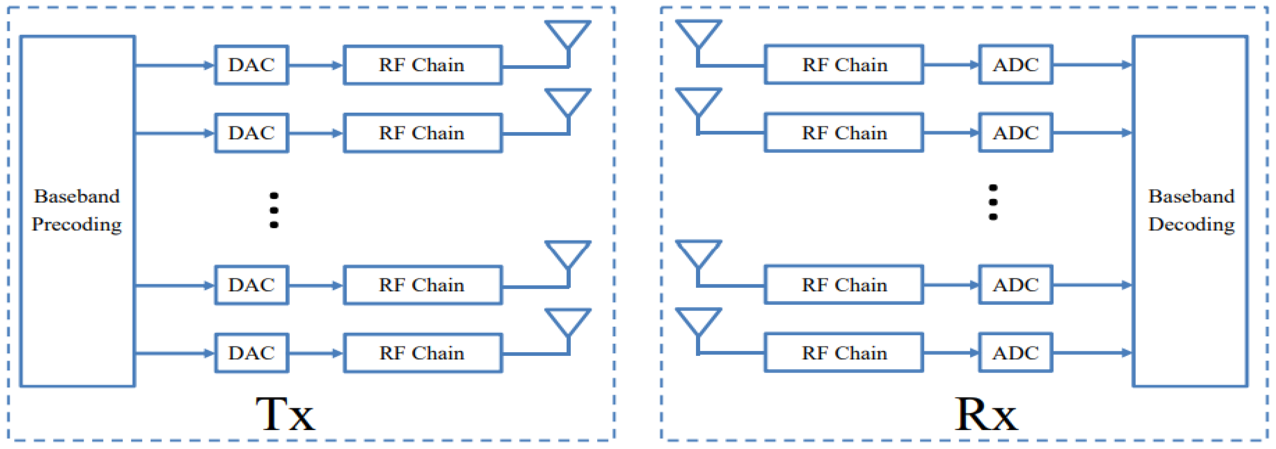
In order to attain more bandwidth than traditional frequency bands, 5G and the following 6G mobile networks operate in high-frequency zones [12]. This allows for high-capacity wireless transmission of data at speeds up to several gigabits per second (Gbps) [13]. It is generally agreed that mmwave communication [14] is one of the most crucial technologies for reaching peak data rates of 10 Gbit/s [15]. This is due to the fact that increasing the bandwidth is an effective method for increasing the system’s capacity [7] and that there is a lot of bandwidth available in the mmwave channels. Measurement and modeling of mmwave channels [16] and assessment of the band’s potential for future wireless systems have received significant academic and industrial attention because of the spectrum’s abundance [17]. However, due to negative propagation effects, particularly those brought on by obstructions in the line of sight (LoS), these high frequencies have been used only sparingly up to this point [18]. It is important to handle the greater propagation losses associated with mmwave frequencies, especially beyond 100 m and in non-line of sight (NLoS) environments [19]. On the one hand, signal transmission becomes more difficult in areas with dense foliage and higher propagation loss [20]. Nonetheless, the link could be forced into the low signal-to-noise ratio (SNR) zone due to the constrained send signal power dispersed over a broad bandwidth [21]. To address these problems, several transceiver topologies have been created that steer the received or broadcast beams in the appropriate direction. [22]. The two main technologies that will enable 5G mmwave communication are MIMO and beamforming [23]. Beamforming is a method for using MIMO/array elements to direct the main lobe radiation beam at the transmitters and receivers in the desired directions, eliminating the undesirable spatial selectivity [24]. The beamforming array is widely divided into the following categories: analog, digital, and hybrid beamforming array [25]. Figure 1 shows the block diagram of massive MIMO system.

2.1.1. Analog Beamforming

The architecture of analog beamforming is shown in Figure 2. A phased array is used to accomplish analog beamforming, and the single RF chain is powered by either an analog-to-digital converter (ADC) in the receiver or a digital-to-analog converter (DAC) in the transmitter. Frequency-up converters, power amplifiers, and other components form a transmitter’s RF chain; low-noise amplifiers, frequency-down converters, and other components form a receiver’s RF chain [27].
The phased array’s antenna weights are required to be digitally controllable phase changes. The relative amplitudes of the signal sent into the antennas of the transmitter cannot be adjusted, and the phases of the phase shifters are normally quantized to low resolution [28]. A beam is created as a result of the send signal, which is constructive in certain directions and destructive in others. On the basis of precise beam-steering tactics, the phase shifters’ phases can be dynamically changed. The receiver has a similar set of features [27].
Figure 2. An mmwave MIMO system using analog beamforming [29].
Electronics 12 00400 g002

2.1.2. Digital Beamforming

The radio frequency (RF) signal in a digital array is transformed into a digital signal at the sub-array or element level, and beamforming is accomplished using a digital signal processor [30]. In order to process the control signals for beamforming, a digital signal processor is used, which offers additional flexibility and degrees of freedom for the implementation of effective beamforming algorithms. Due to the method’s requirement for a separate RF chain for each antenna element, it consumes a great deal of power and has a complicated architecture [31]. Figure 3 shows the structure of digital beamforming.

2.1.3. Hybrid Beamforming

Recently, interest in the hybrid analog/digital beamforming array has increased [32,33]. This type of array increases the efficiency of analog beamforming while reducing the complexity of digital beamforming [34]. The hybrid beamformer is composed of two parts: an analog and a digital component [35]. The RF chains that compose the digital portion share a common structure with the many plans under discussion. For each user on each subcarrier, a hybrid beamforming’s digital component can be used, just like in traditional fully digital beamforming. In contrast, this is not true of the hybrid beamforming analog network or analog component. Since the transmitted signals for all users are combined by the digital beamformers and analog RF beamforming is a post-IFFT (inverse Fast Fourier Transform) operation, all users and subcarriers in an analog network share the same RF component [36]. Hybrid beamforming’s fundamental architecture is depicted in Figure 4.
Beam squint is a phenomenon caused by the frequency dependence of the magnitude of the phase shift in analog beamforming [37]. This can cause issues with wideband communication. The Digital Signal Processing (DSP) logic and digital beamforming algorithms can both use actual time delay. As a result, a phased array architecture with every element digitalized would naturally lend itself to solving the frequency dependency problem as well as offer the greatest degree of programmable flexibility. However, issues with this solution’s strength, size, and price can arise.
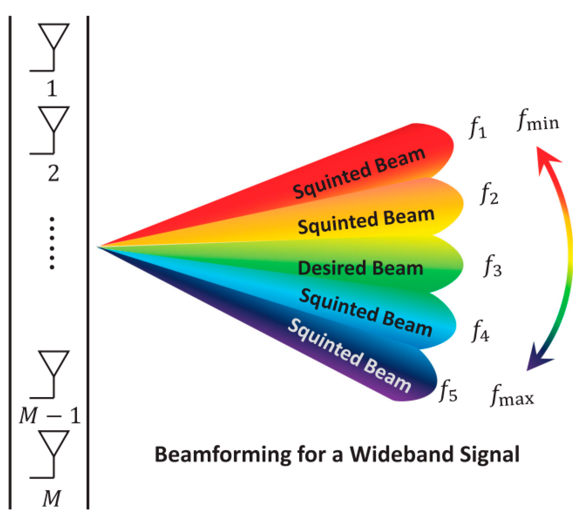
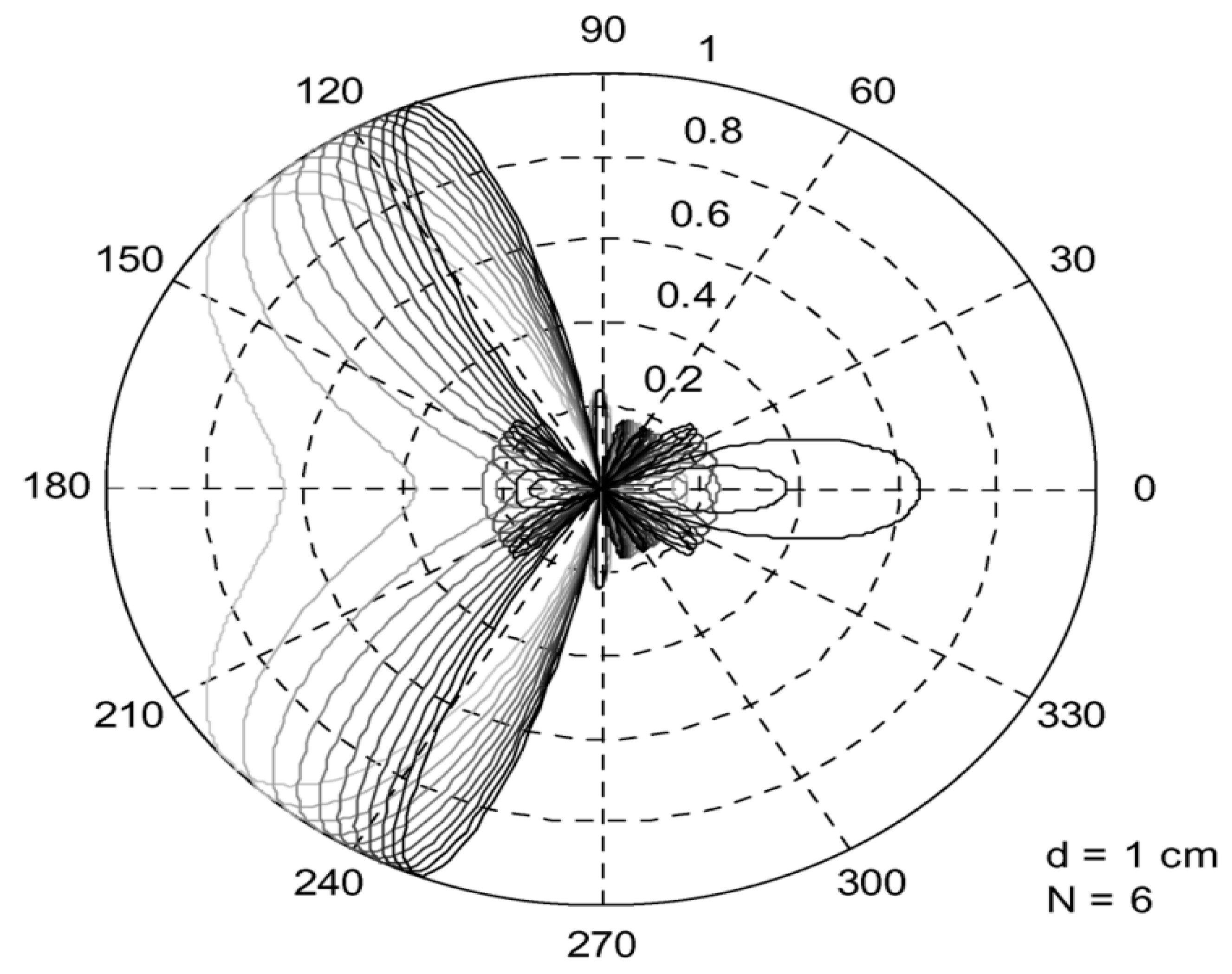
A time delay among elements occurs as a wavefront approaches an array of elements, and it depends on the wavefront angle in relation to boresight. The beam steering can be achieved with a single frequency by substituting a phase shift for the time delay [38]. This is true for narrowband waveforms, but in wideband waveforms when a phase shift is used to provide beam steering, the beam’s direction can change with frequency. As a result, the needed phase shift varies with frequency for a given beam direction. Alternately, the beam direction varies with frequency for a given phase shift. Beam squint is the effect where the beam angle changes depending on the frequency [39]. Figure 5 and Figure 6 shows the effect of beam squint.
In addition, keep in mind that there is no phase shift between the elements at boresight (θ = 0°); hence, there is no way to induce any beam squint. As a result, both the frequency variation and the angle must be functions of the amount of beam squint [38]. Beam squint can seriously affect performance since mmwave communications depend heavily on accurate beam alignment between the transmitter and the receiver [40].

2.2. Effect of Beam Squint on the Communication System Performance

  • Bandwidth and Capacity:
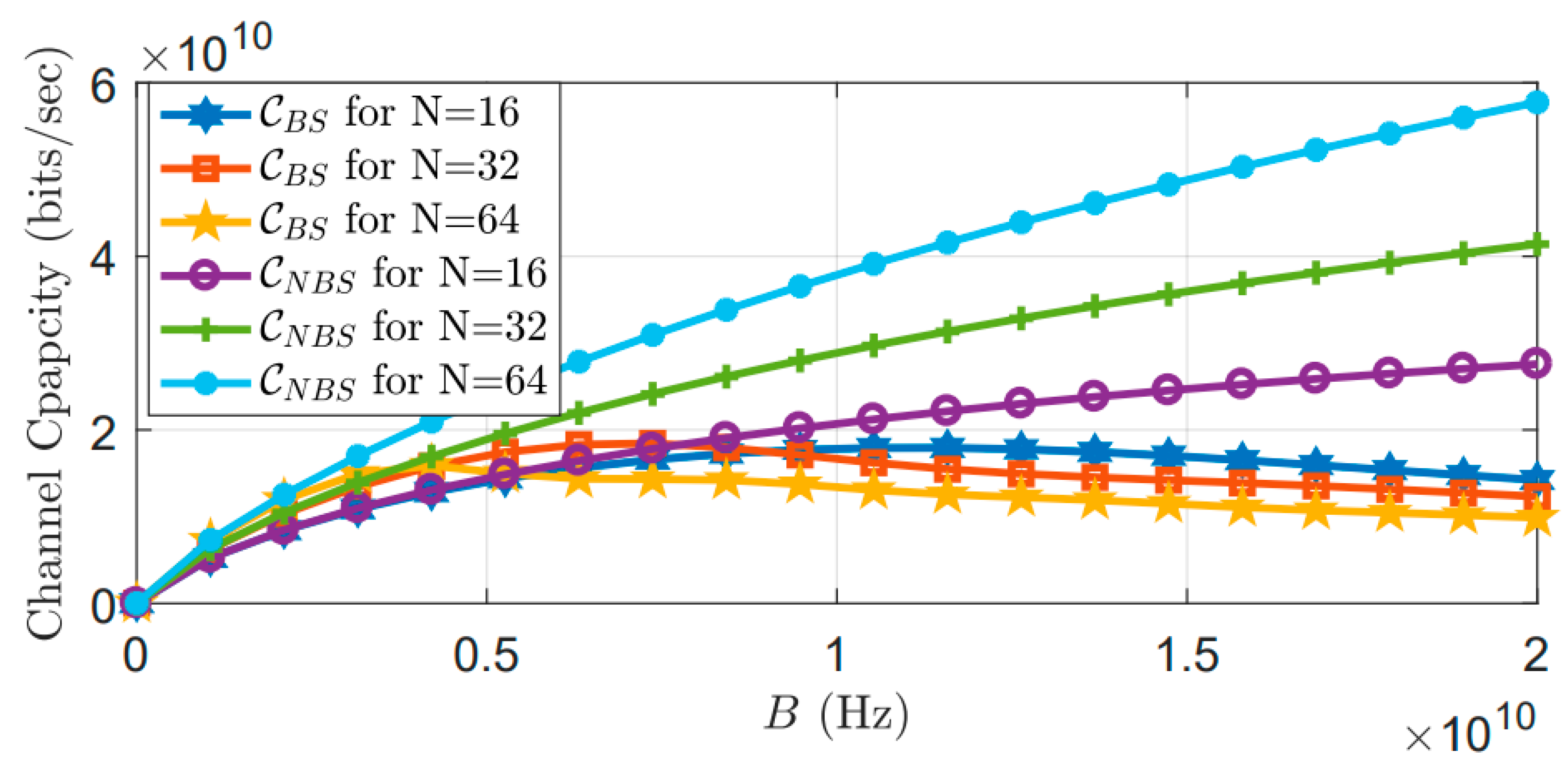
The system bandwidth in wideband communication is constrained by the beam-squint phenomenon [41]. The beam squint effect is closely correlated to bandwidth; as bandwidth rises, the beam squint effect becomes more pronounced, and a larger fraction of the subcarriers experience tiny array gains. Even outside the main lobe, certain subcarriers may exist. As a result, the whole system’s capacity starts to decline [42]. Figure 7 shows the channel capacity versus the bandwidth with and without beam squint. It is clear from this figure that the capacity decreases as the array’s element count, fractional bandwidth, and beam focus angle rise.
  • Channel estimation:
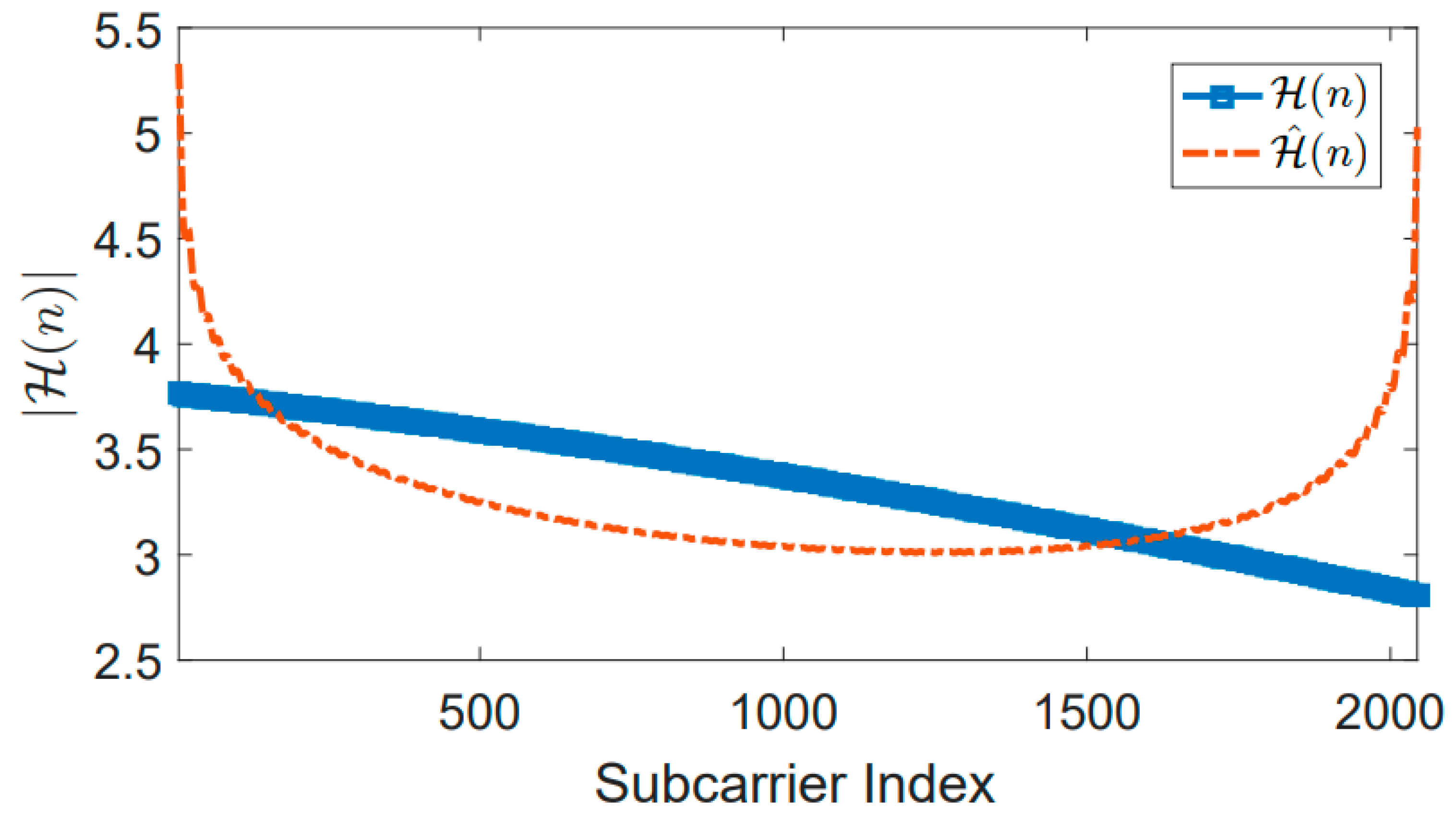
Channel estimation algorithms for Orthogonal Frequency Division Multiplexing (OFDM), Maximum Mean Square Error (MMSE) estimator, and Maximum Likelihood Estimation (MLE) estimator are widely used [41]; however, these estimators do not consider beam squint phenomena. In [42], the MLE channel estimator was used to investigate the effect of beam squint on the estimation process, Fading was considered fixed, and the results showed that beam squint increases the error of channel estimation, even without any noise. The error also increases with increasing the number of antenna elements in the array, fractional bandwidth, and the magnitude of beam focus angle. Figure 8 shows an example of the MLE channel estimation with beam squint, where H(n) represents the true channel, and H ˆ (n) represents the estimated channel. It is clear from this figure that there is a difference between the actual channel and the estimated channel, even without considering the noise.

3. Studies Related to the Beam Squint Effects

Since the 1990s, beam squint phenomena in antenna attracted much attention; in [43], the authors drew a comparison between prime focus beam squint and offset fed of microstrip reflect arrays. Results from an examination of a linear reflectarray are presented, and a straightforward criterion for decreasing beam squint with frequency is discussed.
The author in [44] describes the design of a tri-mode matched feed horn in order to counteract the effects of beam squinting in a circularly polarized offset parabolic reflector antenna. Three modes—TE11, TM11, and TE21—are merged in a conical horn at the correct amplitude and phase ratio to provide a tri-mode matched feed arrangement. The circularly polarized offset parabolic reflector antenna is then lit using the suggested tri-mode horn as the primary feed mechanism. The radiation parameters of the offset reflector are simulated, the amount of beam squinting is calculated, and the results are compared with those of a conventional offset reflector fed by a potter horn. The study also includes the experimental findings regarding the secondary radiation pattern.
In [45], in order to calculate beam squinting in a phased array antenna system, a general formula was created. This formula is especially useful for estimating wide band beam squinting (time-delay) in phased array antenna systems. To determine beam squinting, the authors calculated the criterion (fϕ = 0, cell) from the delay cell’s phase-transfer function, then used (fϕ = 0, cell) as a parameter in the beam-squinting formula.
In radar communications, the beam squint phenomena were studied in [46]. By employing phase shifters as opposed to time-delay, Matt Longbrake was able to construct a formula for beam squint and demonstrated how the array factor varies. In order to address the beam squint issue, true temporal delay (TTD) beam steering was applied using two different techniques, the first of which was dubbed optical delay lines, and the second, electronic delay lines. In the first technique, an RF signal was used to modulate a laser diode’s bias current. A length of optical fiber delays the light, which is subsequently transformed by a photodetector back into an electronic signal.
The main drawback of optical time delay was the modulator’s and detector’s subpar RF performances, particularly insertion loss. Traditional microstrip lines or coax wire was employed in electronic technologies to delay the signal. Overall, the results demonstrated that TTD beam steering outperforms phase shifters; however, this implementation came at a considerable cost and complexity of the system.
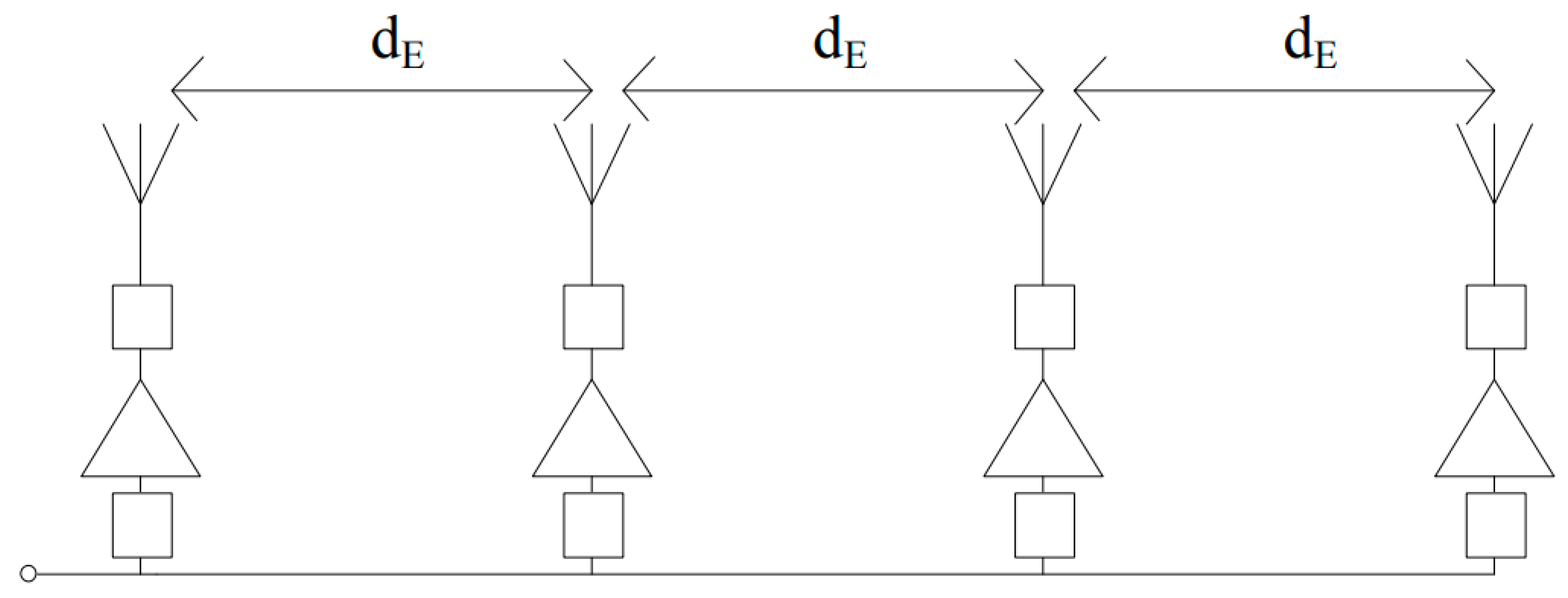
Waleed A. and Amir M. in [47] implemented a novel design for a serially fed antenna array using a negative group delay (NGD) in their study of the beam squint problem in mobile communication [48]. Each active antenna unit included an amplifier, a T-junction power divider, and an antenna in the array of series-fed active antennas that composed the design (see Figure 9).
Beam squinting was a significant problem with the conventional series-fed antenna array. To solve this issue, the phase shift among the antennas should be frequency-independent. In other words, there cannot be a delay in the group. To achieve zero-group delay between the adjacent antennas, a negative group delay (NGD) circuit was added to the feed line. The variance of phase shift with frequency was decreased and the beam squint was minimized by fusing the NGD circuit with the connecting line. With no additional losses, this method significantly reduced the beam squint problem by a factor of six.
In [49], the authors investigated the 60 GHz mmwave wireless communication beamforming process’s beam squint issues in 2013. The goal of beamforming was to choose the best weight vectors for the transmitter and reception antennas with high antenna gains or the best beam pattern pairings, and this criterion depended on several factors, including capacity, the signal-to-noise and interference ratio (SNIR), and others. It was found that the phenomena of beam squint are caused by distinct frequency bands away from the 60 GHz core frequency.
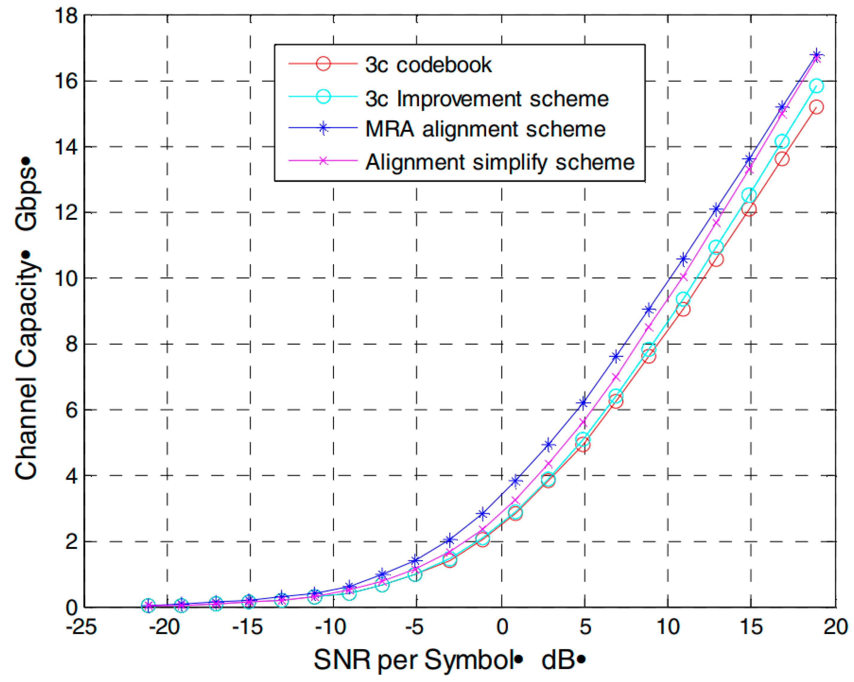
The authors established three different codebook strategies in order to cut down on beam squint. The initial methodology is referred to as the “Phase Improvement Scheme Based on 3C Codebook.” The authors of this plan developed codebooks for a number of different bands and altered the phase by utilising an additional phase shifter. The suppression of the beam squint resulted in a reduction in the amount of spatial interference and an increase in system capacity. On the other hand, the enhanced system capacity came at the expense of an increase in the complexity of the implementation. A comparison of the most common approaches of removing the squint effect from beams is shown in Table 1.
The authors proposed the “MRA Alignment Scheme Based on Uniform-Weighting Codebook” as the second scheme to enhance system performance. The final proposal assumed that since neighboring parts have a strong correlation, it was possible to alter the phase of two nearby antennas using a single-phase shifter, which significantly reduced the complexity of the transceiver.
Figure 10 shows compression among the three schemes as a function of the system capacity. Although these schemes worked very effectively in removing the beam squint, they increased the system complexity by increasing the number of phase shifters.
In [50], the beam squint problem in Uniform Linear Array (ULA) was modelled, and its effect on codebook design was analyzed. The study demonstrated that beam squint reduces the bandwidth that is usable. The authors created an algorithm to fix codebook designs with beam squint. The goal of codebook design was to ensure that every beam exceeds a specified threshold and has a minimal gain for a variety of frequencies and angles in the wideband system. Analysis and numerical examples indicated that to account for beam squint, a denser codebook was needed. In other words, compared with a codebook design that disregards beam squint, more beams were required.
In order to boost the expected average beam gain, the authors of [51] studied the beam squint issue in mmwave communication and suggested a beamforming architecture that optimizes average beam gain inside the bandwidth while minimizing average beam gain outside the bandwidth. Additionally, the design shows little variation in the bandwidth at various frequencies. To take into account the beam squint and guarantee constant beam gain for each subcarrier in the wideband system, the authors suggested a beamforming approach based on space–time block coding. In order to offer a less-than-ideal answer, on the basis of eigenvalue decomposition, the semidefinite relaxation (SDR) approach was applied. The simulation results showed that, under specific circumstances, the suggested transmission method can effectively reduce beam squint and improve wideband communication systems’ throughput performance.
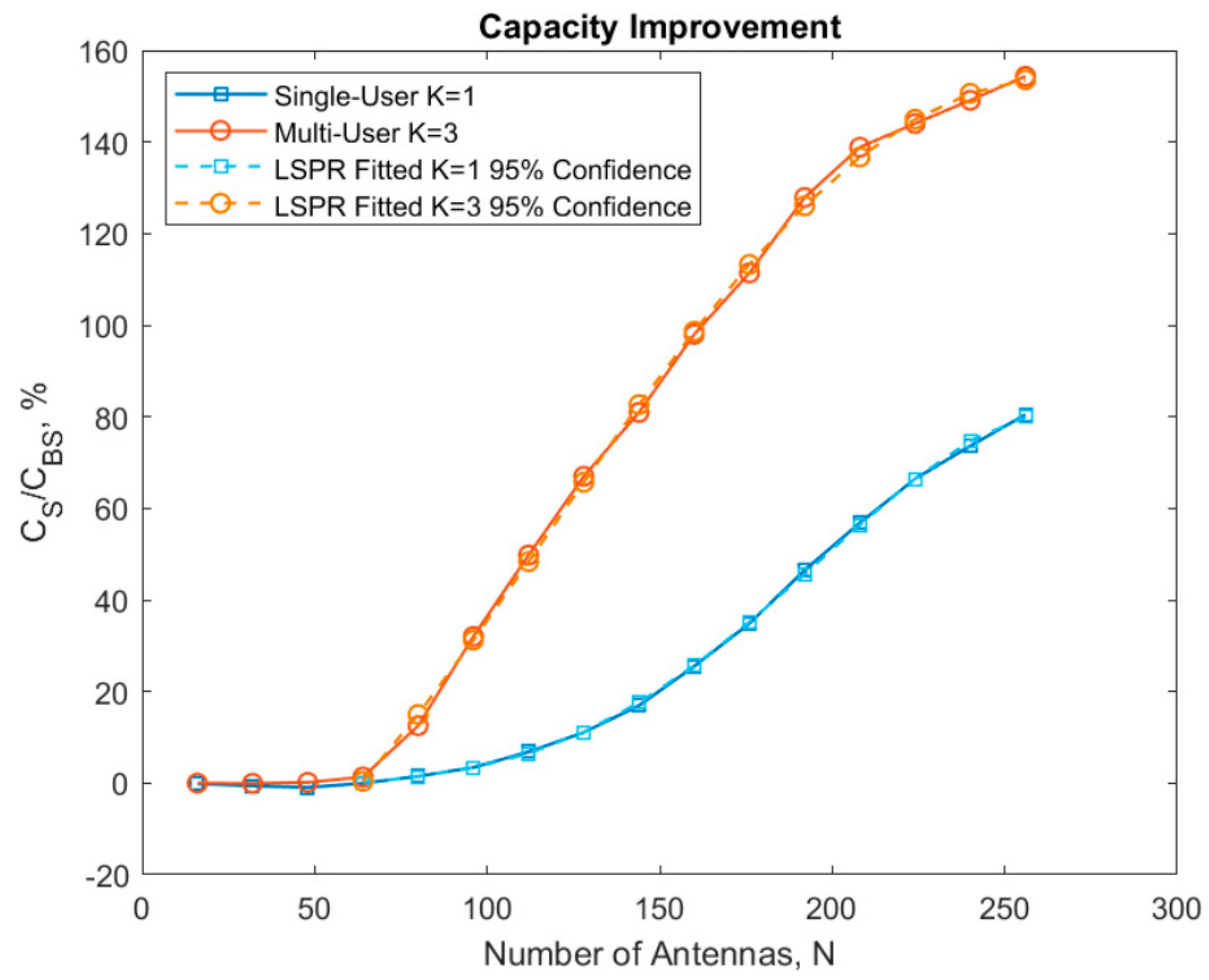
In order to demonstrate how the number of antenna elements influences beam squint and how wideband beam squint affects the traditional narrowband models, an analysis of capacity was carried out in [52]. Combining two state-of-the-art cooperative algorithms led to the suggestion of a method for assigning subcarriers to beams. The first methodology determines the optimal beams for allocation in a multi-carrier implementation and determines how much beam squint is present in the system, whereas the second methodology maps data to the appropriate beams. The results of the investigation showed that beam squint significantly affected system capacity. The results also showed that beam squint might be utilized to better manage resources and expand system capacity, as shown in Figure 11.
The beam squint effect on channel estimation had been analyzed in [53]. In this study the authors clarified that beam squint in an MIMO-OFDM system causes the subcarriers to see distinct angles of the same path and renders the existing channel estimation and precoding algorithms inapplicable. For frequency-division duplex (FDD) mmwave massive MIMO-OFDM systems with hybrid analog/digital precoding, the authors suggested a channel estimation approach that takes the beam squint effect into account. The angle of arrival (AoA) and time delay, which are frequency-insensitive parameters of each uplink channel path, as well as the complex channel gain, which is frequency-sensitive, were extracted using a compressive sensing-based methodology. The reciprocity of these frequency-insensitive parameters in frequency division duplex (FDD) systems allows for a significant simplification of the downlink channel estimating process, using only a small number of pilots to acquire the downlink complex gains and reconstruct the downlink channels. The results of this study showed that the proposed channel estimation scheme can perform better than the other conventional methods under general system configurations in mmwave communication.
The authors of [54] developed an off-grid CSS technique to calculate the uplink channel and offered a non-negligible beam squint in the field of channel estimation with beam squint. According to the authors, the direction of arrival (DOA) and the delay parameters might be calculated from the signals received on the uplink channel’s pilot subcarriers using a shift-invariant block-iterative gradient technique. The entire set of channels over all subcarriers was then rebuilt using the DOA and delay settings. The outcomes demonstrated that this offered superior outcomes in comparison with previous approaches that neglected to account for beam squint.
The authors in [55] present a unique digital method for correction of beam squint by utilizing Nonlinear Frequency Modulation (NLFM) Tansec waveforms when addressing phase-based phased array antennas. An algorithm was designed that chooses Tansec waveforms with phases that rectify FM-induced phase variations in the necessary transmitted signals phases. Simulations for a typical 77 GHz automobile radar with a 3 GHz BW show that the suggested technique can reduce beam squint.
The authors of [56] examined the issue of estimation of channel for mmwave MIMO systems with hybrid beamforming. A beam squint for channel estimation and an asymptotically ideal analog-beam scanning and pilot tone allocation system were developed. The suggested architecture is expanded to include the Uniform Planar Array (UPA) situation that satisfies the channel vectors’ asymptotic orthogonality. To further support the effectiveness of the proposed design, a numerical comparison with the computed Cramer Rao lower bound (CRLB) was performed.
The wideband mmwave communication supported by a reconfigurable intelligent surface (RIS) suffering from the beam-squinting effect was first studied by [57]. Each component of the RIS is a nearly passive device, similar to the phase shifter [58], and it is a novel sort of “array” that has garnered considerable interest from both academics and the industry. Compared with a conventional antenna array, which has energy-hungry radio frequency chains, RIS is able to adaptively reflect the incident signals in the desired directions while using less power. Given that a passive reconfigurable intelligent surface (RIS) is applied in time domain and that mmwaves communications will have bandwidths up to several GHz, the phase shifts are assumed symmetrical for all frequencies. This will result in significant performance degradation. Several phase shifter design ideas were put forth to address the beam squint issue, taking into consideration both line of sight and non-line of sight instances.
A near-optimal phase shift design approach was developed, which is dependent only on the long-term angle data after identifying the best phase shift for each frequency in the LoS scenario. To achieve this, the obtained upper bound of the cumulative attainable rate was maximized. For the non-line of sight (NLoS) scenario, a method based on the mean channel covariance matrix (MCCM), was presented in order to determine the common phase shift for all frequencies. When a large number of components or a high bandwidth were used in the RIS, the detailed numerical analyses showed that the beam squint would result in a performance loss of more than 3 bps/Hz, and the effectiveness of the suggested approaches was proven to lessen the influence of the beam squint.
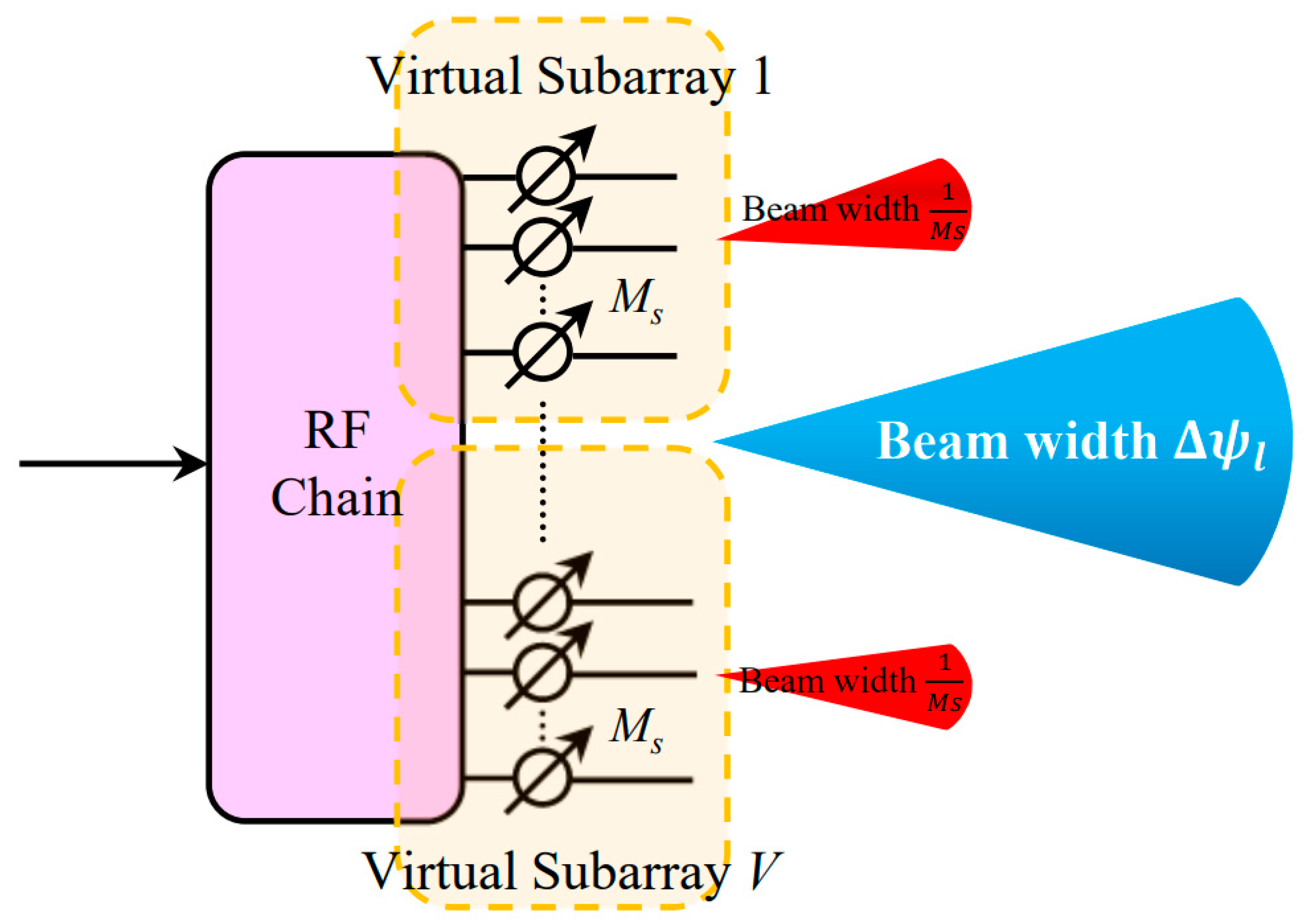
In [59], two wideband hybrid beamforming techniques were proposed. The authors’ first approach suggested dividing the array into virtual subarrays, as illustrated in Figure 12, to produce a bigger beam and provide an evenly distributed array gain across the entire operational frequency spectrum. Results showed that this technique can reduce beam squint to some extent.
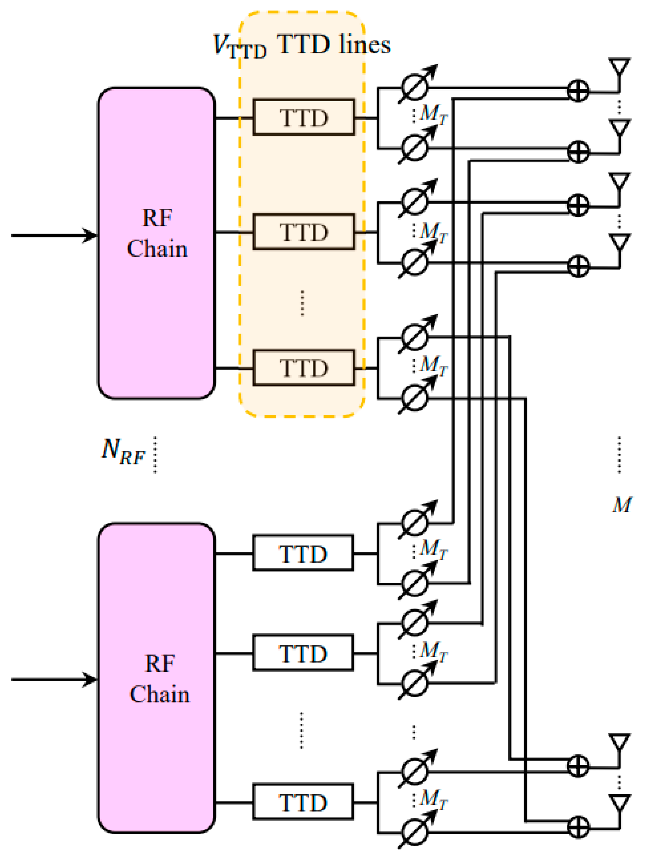
The second method modified the analog beamformer/combiner for a hybrid phased array transceiver on the basis of true time delay lines (TDD). Instead of replacing the phase shifters entirely, a small number of TTD lines are utilized to reduce the costs. The phase shifters were divided into groups and each group had one TTD line, as shown in Figure 13. The results of this method showed better results in removing beam squint while reducing the cost.
In [60], the authors investigated the impact of beam squinting on single carrier frequency domain equalization (SC-FDE) transmission systems used in mmwave communications. In high-throughput mmwave LoS multiple-input single-output (LoS-MISO) systems, the response of a uniform linear array (ULA) antenna and the common analog beamforming vector was described as a spatial equivalent channel. It was discovered through analysis of the spatial equivalent channel’s characteristics that it behaves similarly to frequency-selective fading. The spatial equivalent channel’s deep fading points were eliminated using an improved analog beamforming technique based on the Zadoff-Chu (ZC) sequence. The receiver then uses low-complexity linear zero-forcing and minimal mean squared error equalizers to reduce ISI brought on by the beam squint. The simulation results show that the proposed analog beamforming based on ZC can successfully reduce the performance impact of beam squint.
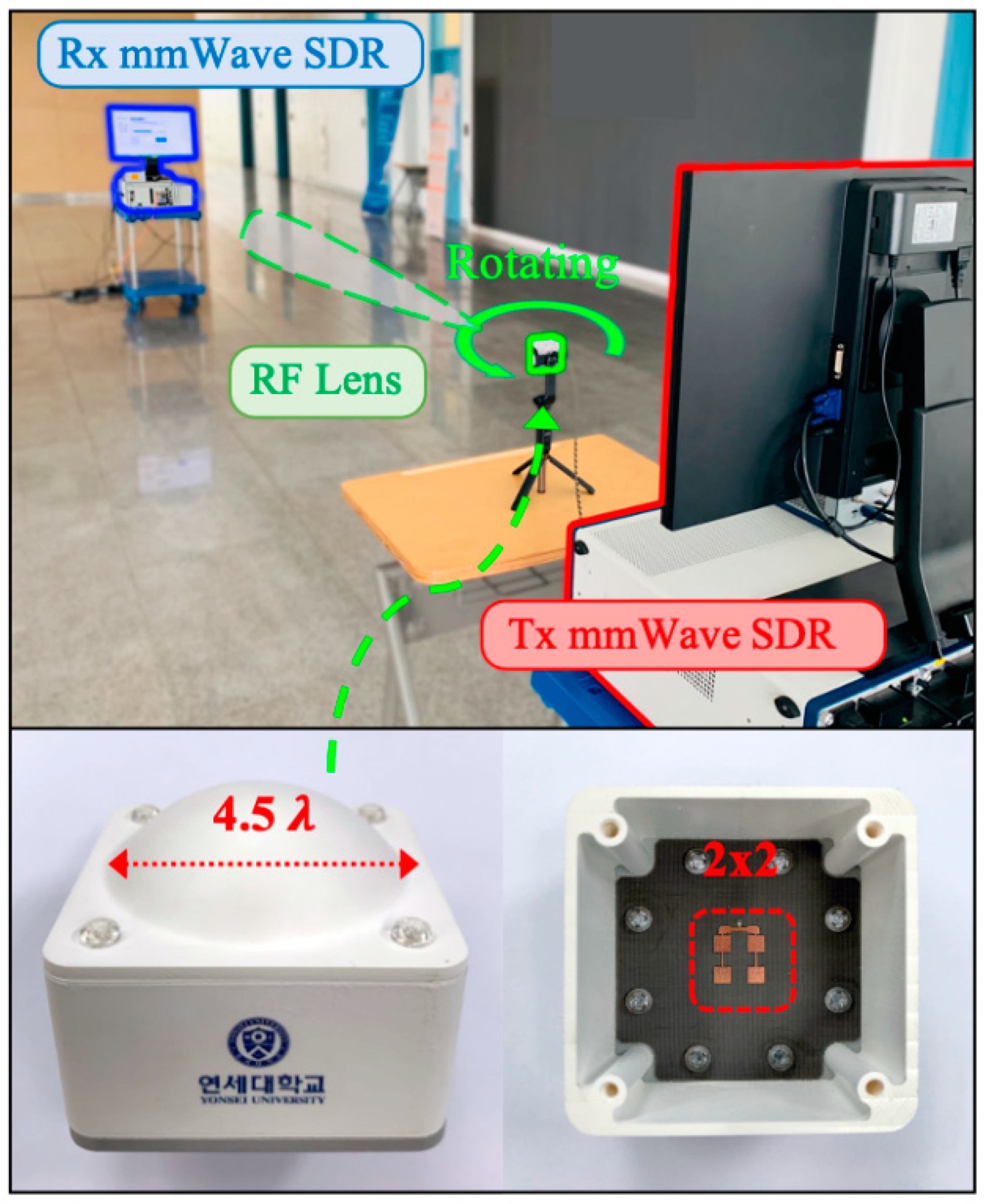
Beam squint in RF lens antenna was discussed in [61] for ultra-wideband millimeter-wave (mmwave) systems. According to the authors of this study, phased array antennas are not affected by the same factors that cause RF lens antenna beam squint. According to Snell’s law, if an electromagnetic wave passes through a dielectric lens, it will be bent. Refraction is a result of permittivity being a function of frequency, one of the reasons of beam squint, according to the Drude–Lorentz model [62]. Due to the resonance frequency and damping constant, permittivity is also nonlinear. Permittivity has both genuine and fictitious components. The real component is represented by the dielectric constant, and the tangent loss is the ratio of the real to the imaginary component. As can be seen, the component of the refractive index, known as the real part, is the one that determines the degree to which the beam is deflected. Because permittivity affects the actual portion of the refractive index, the beam squints at the lens when a wave with a different frequency band travels through a material with a different degree of refraction, as shown in Figure 14. This occurs because a wave with a different frequency band travels through a material with a different degree of refraction.
To make fully digital beamforming less complicated, the authors developed hybrid beamforming. The lens structure at the front of the antenna array and the antenna array itself formed the two components of the RF lens antenna. The analog beamforming process uses the lens structure to concentrate the beam produced by the antenna array. With the antenna switched on and off, beam steering was accomplished utilizing lens refractions. Under comparable circumstances for beam squint, beamforming gain, and received power, the authors compared and contrasted the lens antenna and the phased array. Through study, they were able to confirm that stable permittivity materials can be used to minimize the beam squint issue with the RF lens system. Then, they demonstrated the reduced spectral efficiency brought on by beam squint for both the lens antenna and the phased array using 3D ray tracing in an interior setting. Finally, they used the constructed RF lens to illustrate the indoor mmwave link level and to confirm that beam squint negatively affects performance.
In [63], the authors proposed a transceiver design based on lens antenna subarray (LAS) and analog sub-band filters to compensate for the beam squinting. The design is based on the idea of dividing the ultra-wideband signal into narrowband beams and controlling them with a simplified exhaustive search-based precoding that is proposed to align the beam angle to the target direction. Analysis was based on various performance parameters, such as beam gain, complexity, power consumption, and capacity. The proposed design involved using both phase shifters and switching networks to steer the beam to compensate for the beam-squinting problem while maintaining the intended beamwidth performance. Phase shifters were used to steer the beam to the desired direction on the basis of the location of the targeted user, and the switching mechanism was used to select an antenna element under the lens that can correct/minimize the deviation of the beam (due to squinting) from the intended direction. The results of this study showed significant performance improvement. However, this study requires the use of high-quality narrowband filters for higher frequencies. This can increase the complexity of the system as well as the cost.
Another approach, based on reconfigurable intelligent surface for satellite-to-terrestrial relay networks, was developed and described in [64]. The Taylor expansion and penalty function methods were used in this approach to optimise phase shifters between the surface unit cells by adding a weight function in order to maximise the channel performance under certain conditions.

4. Studies Related to the Beam Squint Exploitation

Beam squint is not always a bad thing; the idea of the main beam changing direction with frequency was appealing for many researchers, and some studies even used it to enhance system performance. For instance, in [65], the authors formed many beams using the beam-squinting property of planar arrays using wideband perfect phase shifters instead of an existing hybrid structure. The following steps can be used to describe the work: initially, the authors determined the beam characteristics of the wideband array. Second, they created a coplanar array using the concept of the fractal that can operate across three mmwave frequency bands. The array’s phase shifter was then swapped with one based on cells, as shown in Figure 15, which illustrates the steps for the suggested Sierpinski carpet antenna array with three antenna tiers, and in Figure 16, which illustrates the extensions and variations of the three-tier Sierpinski carpet array. Finally, they created the squinting multi-beam algorithm that facilitates multi-user communications on the basis of the beam-squinting property of the wideband array with optimal phase shifters. Under ideal circumstances, the study demonstrated an improvement in system performance (mutual coupling and isotropic elements were assumed).
In [66], a joint optimization design based on non-orthogonal multiple access-based satellite–terrestrial integrated network at mmwave was developed for cellular network technology. They developed, in their work, a user pairing scheme, therefore; non-orthogonal multiple access technique was exploited through grouping more than two users in the same cluster.
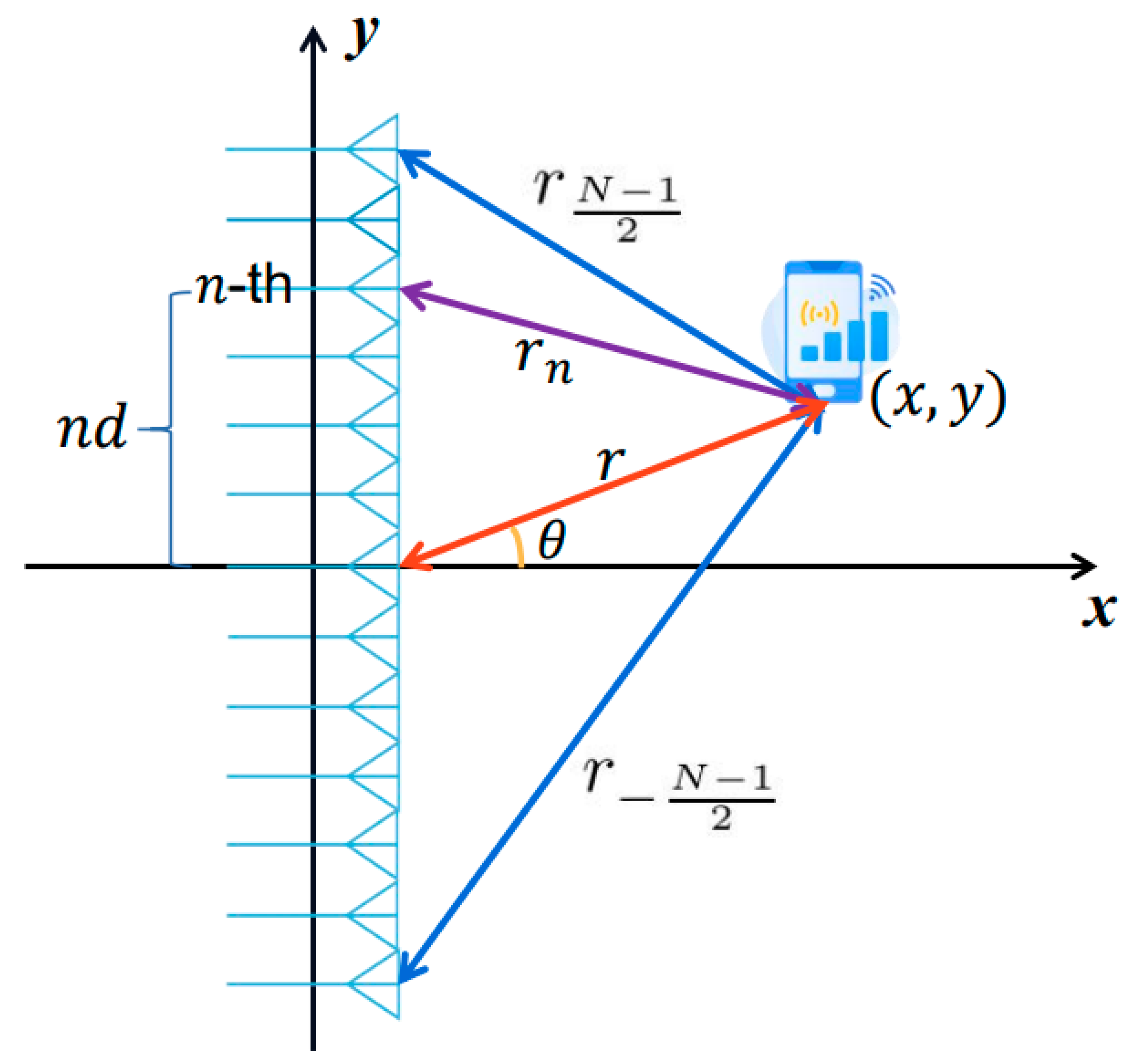
In [67], the authors explained how beam squint can be utilized for user localization. The author’s idea was to control the beam squint using time delays and using it for localization. They created a method to regulate the trajectory of these beam squint points by deriving a trajectory equation for near-field beam squint points, as shown in Figure 17. In order for users in various positions to obtain the most power at various subcarriers, beamforming from various subcarriers would purposefully point to various angles and distances. Therefore, using the beam squint effect, one can easily determine the positions of the various users. The efficiency of beam squint in user localization can be shown from the study’s findings. In addition, the same authors in [67] applied an advanced technique, called reconfigurable intelligent surface (RIS) [68], which suppressed the beam-squinting effect in broadband mobile communication.
We believe that, in the future, there will be a considerable number of studies that, rather of focusing on eliminating beam squint, would instead focus on using it in a certain way in order to accomplish a certain goal. As a direct consequence of this, mmwave communication systems will become simpler and less expensive. Table 2 is a synopsis of the studies that were conducted on beam squint by a number of different people, and it lists the conclusions from that research. We have accomplished all that is within our ability to answer the most pertinent results and remarks, in addition to the several types of methods that were used in these studies. It was found that the tradeoff between the array size and the reduction of the impacts of beam squint was significantly similar and directly related to the cost and design complexities of the hardware that was employed for these systems. This was found to be the case after it was discovered that these two factors were directly related to each other.

5. Conclusions

In this paper, a literature review has been introduced to analyse the relative issues of the squint phenomena of mmwaves in antenna arrays for modern communication systems. It is found that such problems become very effective at high-frequency bands due to the dispersion effects of antenna arrays in terms of angle of arrival and gain variation, which directly effect the channel performance. For this purpose, the authors classified the main effective solutions to resolve such problems, which include beamforming, antenna geometry, and channel estimation algorithms. Another classification can be considered that exploits the beam squint to take advantages from squint phenomena to enhance the channel localization and capacity through splitting the beam to different directions. In spite of these classifications, beamforming, for example, based on digital processes, realizes an excellent solution to minimize the effect of beam squint on bit error rate and channel capacity, however; it consumes high complexity with excessive cost. The relative algorithm based on channel estimation could be considered the next revolutionary approach, whereby the system consumes less hardware complexity and cost. However, it is very limited when the channel environment becomes highly dynamic, which consumes high delay in the data processing. For this reason, it becomes unreliable with increasing traffic and signal attenuation. The third classification is assumed to be a solution method; however, it is not. It is indeed a suggestion to avoid the negative effects of such phenomena by splitting the beam of the antenna array to support channel localization and create multiuser communication channels. In view of the previous indications, a possible connection is found between the proposed classes to create a hybrid mixture to realize a high impact on the channel performance enhancement. This conclusion is built on the fact of dispersion, which is a relative problem with antenna arrays, channels, and subcarriers that cannot be resolved from one side and neglected from the other two. Therefore, for future research, a new technique must be recognized to find a complete solution that takes into the account beam squint effects at all communication system parts, thus leading us to fill the gaps in the developments in mmwave communication system for 5G and beyond.

Author Contributions

Investigation and original draft preparation, M.Q.A., supervision, methodology and review, A.H.M., Conceptualization, review and editing, R.A.A.-A. All authors have read and agreed to the published version of the manuscript.

Funding

Authors thank the support of the higher education ministry from Iraq.

Conflicts of Interest

There is no conflict of interest.

References

  1. Cihat, S.; Muhammet, T.; Turgut, O. A Review of Millimeter Wave Communication for 5G. In Proceedings of the 2018 2nd International Symposium on Multidisciplinary Studies and Innovative Technologies (ISMSIT), Ankara, Turkey, 19–21 October 2018; IEEE: New York, NY, USA, 2018. [Google Scholar]
  2. Ullah, H.; Nair, N.G.; Moore, A.; Nugent, C.; Muschamp, P.; Cuevas, M. 5G Communication: An Overview of Vehicle-to-Everything, Drones, and Healthcare Use-Cases. IEEE Access 2019, 7, 37251–37268. [Google Scholar] [CrossRef]
  3. Duong, T.; Elkashlan, M. Millimeter-wave communications for 5G: Fundamentals. IEEE Commun. Mag. 2014, 52, 52–54. [Google Scholar]
  4. Wei, L.; Hu, R.Q.; Qian, Y.; Wu, G. Key elements to enable millimeter wave communications for 5G wireless systems. IEEE Wirel. Commun. 2014, 21, 136–143. [Google Scholar]
  5. van Berlo, B.; Elkelany, A.; Ozcelebi, T.; Meratnia, N. Millimeter Wave Sensing: A Review of Application Pipelines and Building Blocks. IEEE Sensors J. 2021, 21, 10332–10368. [Google Scholar] [CrossRef]
  6. Mohanty, S.; Agarwal, A.; Agarwal, K.; Mali, S.; Misran, G. Role of Millimeter Wave for Future 5G Mobile Networks: Its Po-tential, Prospects and Challenges. In Proceedings of the 2021 1st Odisha International Conference on Electrical Power Engineering, Communication and Computing Technology (ODICON), Bhubaneswar, India, 8–9 January 2021; pp. 1–4. [Google Scholar]
  7. Rappaport, T.S.; Sun, S.; Mayzus, R.; Zhao, H.; Azar, Y.; Wang, K.; Wong, G.N.; Schulz, J.K.; Samimi, M.; Gutierrez, F. Millimeter wave mobile communications for 5g cellular: It will work. Access IEEE 2013, 1, 335–349. [Google Scholar] [CrossRef]
  8. Bogale, T.; Wang, X.; Le, L. Chapter 9–mm-Wave communication enabling techniques for 5G wireless systems: A link level perspective. Mmwave Massive MIMO 2017, 195–225. [Google Scholar]
  9. Wang, M.; Gao, F.; Jin, S.; Lin. An Overview of Enhanced Massive MIMO With Array Signal Processing Techniques. IEEE J. Sel. Top. Signal Process. 2019, 13, 886–901. [Google Scholar] [CrossRef] [Green Version]
  10. Akyildiz, I.F.; Han, C.; Nie, S. Combating the Distance Problem in the Millimeter Wave and Terahertz Frequency Bands. IEEE Commun. Mag. 2018, 56, 102–108. [Google Scholar] [CrossRef] [Green Version]
  11. Busari, S.A.; Huq, K.M.S.; Mumtaz, S.; Dai, L.; Rodriguez, J. Millimeter-Wave Massive MIMO Communication for Future Wireless Systems: A Survey. IEEE Commun. Surv. Tutorials 2017, 20, 836–869. [Google Scholar] [CrossRef]
  12. Sarieddeen, H.; Saeed, N.; Al-Naffouri, T.Y.; Alouini, M.-S. Next Generation Terahertz Communications: A Rendezvous of Sensing, Imaging, and Localization. IEEE Commun. Mag. 2020, 58, 69–75. [Google Scholar] [CrossRef]
  13. Al-Sadoon, M.; Patwary, M.; Parchin, N.; Aldelemy, A.; Abd-Alhameed, R. New Beamforming Ap-proach Using 60 GHz Antenna Arrays for Multi-Beams 5G Applications. Electronics 2022, 11, 1739. [Google Scholar] [CrossRef]
  14. Xiao, M.; Mumtaz, S.; Huang, Y.; Dai, L.; Li, Y.; Matthaiou, M.; Karagiannidis, G.K.; Bjornson, E.; Yang, K.; Chih-Lin, I.; et al. Millimeter Wave Communications for Future Mobile Networks. IEEE J. Sel. Areas Commun. 2017, 35, 1909–1935. [Google Scholar] [CrossRef] [Green Version]
  15. Du, J.; Valenzuela, R.A. How Much Spectrum is too Much in Millimeter Wave Wireless Access. IEEE J. Sel. Areas Commun. 2017, 35, 1444–1458. [Google Scholar] [CrossRef]
  16. Andrews, J.G.; Buzzi, S.; Choi, W.; Hanly, S.V.; Lozano, A.; Soong, A.C.K.; Zhang, J.C. What will 5G be? IEEE J. Sel. Areas Commun. 2014, 32, 1065–1082. [Google Scholar] [CrossRef]
  17. Andrews, J.G.; Bai, T.; Kulkarni, M.N.; Alkhateeb, A.; Gupta, A.K.; Heath, R.W. Modeling and Analyzing Millimeter Wave Cellular Systems. IEEE Trans. Commun. 2016, 65, 403–430. [Google Scholar] [CrossRef] [Green Version]
  18. Swindlehurst, A.L.; Ayanoglu, E.; Heydari, P.; Capolino, F. Millimeter-wave massive MIMO: The next wireless revolution? IEEE Commun. Mag. 2014, 52, 56–62. [Google Scholar] [CrossRef]
  19. Feng, W.; Li, Y.; Jin, D.; Su, L.; Chen, S. Millimeter-wave backhaul for 5G networks: Challenges and solutions. Sensors 2016, 16, 892. [Google Scholar] [CrossRef] [Green Version]
  20. Li, J.; Niu, Y.; Wu, H.; Ai, B.; Chen, S.; Feng, Z.; Zhong, Z.; Wang, N. Mobility Support for Millimeter Wave Communications: Opportunities and Challenges. IEEE Commun. Surv. Tutorials 2022, 24, 1816–1842. [Google Scholar] [CrossRef]
  21. Zugno, T.; Drago, M.; Giordani, M.; Polese, M.; Zorzi, M. Toward standardization of millimeter-wave vehicle-tovehicle networks: Open challenges and performance evaluation. IEEE Communi. Mag. 2020, 58, 79–85. [Google Scholar] [CrossRef]
  22. Kutty, S.; Sen, D. Beamforming for Millimeter Wave Communications: An Inclusive Survey. IEEE Commun. Surv. Tutorials 2015, 18, 949–973. [Google Scholar] [CrossRef]
  23. Bjornson, E.; Van der Perre, L.; Buzzi, S.; Larsson, E.G. Massive MIMO in sub-6 GHz and mm-Wave: Physical, practical, and use-case differences. IEEE Wirel. Commun. 2019, 26, 100–108. [Google Scholar] [CrossRef] [Green Version]
  24. Mandloi, M.S.; Gupta, P.; Parmar, A.; Malviya, P.; Malviya, L. Beamforming MIMO Array Antenna for 5G-Millimeter-Wave Application. Wirel. Pers. Commun. 2022, 1–20. [Google Scholar] [CrossRef]
  25. Herd, J.S.; Conway, M.D. The Evolution to Modern Phased Array Architectures. Proc. IEEE 2015, 104, 519–529. [Google Scholar] [CrossRef]
  26. Araújo, D.C.; Maksymyuk, T.; de Almeida, A.L.; Maciel, T.; Mota, J.C.; Jo, M. Massive MIMO: Survey and future research topics. IET Commun. 2016, 10, 1938–1946. [Google Scholar] [CrossRef] [Green Version]
  27. Bogale, T.E.; Le, L.B.; Haghighat, A.; Vandendorpe, L. On the Number of RF Chains and Phase Shifters, and Scheduling Design with Hybrid Analog–Digital Beamforming. IEEE Trans. Wirel. Commun. 2010, 15, 3311–3326. [Google Scholar] [CrossRef] [Green Version]
  28. Venkateswaran, M.V.; van der Veen, A. Analog Beamforming in MIMO Communications with Phase Shift Networks and Online Channel Estimation. IEEE Trans. Signal Process. 2010, 58, 4131–4143. [Google Scholar] [CrossRef]
  29. Steyskal, H. Digital beamforming. In Proceedings of the 1988 18th European Microwave Conference, Stockholm, Sweden, 12–15 September 1988. [Google Scholar]
  30. Heath, R.W.; González-Prelcic, N.; Rangan, S.; Roh, W.; Sayeed, A.M. An Overview of Signal Processing Techniques for Millimeter Wave MIMO Systems. IEEE J. Sel. Top. Signal Process. 2016, 10, 436–453. [Google Scholar] [CrossRef]
  31. Dan; Dudgeon, E.; Johnson, D.H. Array Signal Processing: Concepts and Techniques; P T R Prentice Hall: Hoboken, NJ, USA, 1993. [Google Scholar]
  32. Sohrabi, F.; Yu, W. Hybrid Analog and Digital Beamforming for mmWave OFDM Large-Scale Antenna Arrays. IEEE J. Sel. Areas Commun. 2017, 35, 1432–1443. [Google Scholar] [CrossRef] [Green Version]
  33. Zhu, G.; Huang, K.; Lau, V.K.N.; Xia, B.; Li, X.; Zhang, S. Hybrid Beamforming via the Kronecker Decomposition for the Millimeter-Wave Massive MIMO Systems. IEEE J. Sel. Areas Commun. 2017, 35, 2097–2114. [Google Scholar] [CrossRef] [Green Version]
  34. Gherekhloo, S.; Ardah, K.; Haardt, M. Hybrid Beamforming Design for Downlink MU-MIMO-OFDM Millimeter-Wave Systems. In Proceedings of the 2020 IEEE 11th Sensor Array and Multichannel Signal Processing Workshop (SAM), Hangzhou, China, 8–11 June 2020; pp. 1–5. [Google Scholar]
  35. Khan, F.; Pi, Z.; Rajagopal, S. Millimeter-wave mobile broadband with large scale spatial processing for 5G mobile com-munication. In Proceedings of the 2012 50th Annual Allerton Conference on Communication, Control, and Computing (Allerton), Monticello, IL, USA, 1–5 October 2012; pp. 1517–1523. [Google Scholar]
  36. Zhang, J.; Yu, X.; Letaief, K.B. Hybrid Beamforming for 5G and Beyond Millimeter-Wave Systems: A Holistic View. IEEE Open J. Commun. Soc. 2019, 1, 77–91. [Google Scholar] [CrossRef] [Green Version]
  37. Cai, M.; Laneman, J.N.; Hochwald, B. Beamforming codebook compensation for beam squint with channel capacity con-straint. In Proceedings of the 2017 IEEE International Symposium on Information Theory (ISIT), Aachen, Germany, 25–30 June 2017; pp. 76–80. [Google Scholar]
  38. Pan, X.; Li, C.; Yang, L. Wideband beamspace squint user grouping algorithm based on subarray collaboration. EURASIP J. Adv. Signal Process. 2022, 2022, 1–14. [Google Scholar] [CrossRef]
  39. Available online: https://www.analog.com/en/analog-dialogue/articles/phased-array-antenna-patterns-part2.html (accessed on 1 June 2020).
  40. Yao, J. Microwave Photonics. J. Light. Technol. 2009, 27, 314–335. [Google Scholar] [CrossRef]
  41. Bonjour, R.; Singleton, M.; Leuchtmann, P.; Leuthold, J. Comparison of steering angle and bandwidth for various phased array antenna concepts. Opt. Commun. 2016, 373, 35–43. [Google Scholar] [CrossRef]
  42. Cai, M. Modeling and Mitigating Beam Squint in Millimeter Wave Wireless Communication. Ph.D. Thesis, Graduate Program in Electrical Engineering, Notre Dame, Indiana, March 2012. [Google Scholar]
  43. Rousseaux, O.; Leus, G.; Stoica, P.; Moonen, M. Gaussian maximum-likelihood channel estimation with short training se-quences. IEEE Trans. Wirel. Commun. 2005, 4, 2945–2955. [Google Scholar] [CrossRef]
  44. Targonski, S.; Pozar, D. Minimization of beam squint in microstrip reflectarrays using an offset feed. In Proceedings of the IEEE Antennas and Propagation Society International Symposium. 1996 Digest, Baltimore, MD, USA, 21–26 July 1996; Volume 2, pp. 1326–1329. [Google Scholar]
  45. Sharma, S.B.; Pujara, D.A.; Chakrabarty, S.B.; Singh, V.K. Removal of Beam Squinting Effects in a Circularly Polarized Offset Parabolic Reflector Antenna Using a Matched Feed. Prog. Electromagn. Res. Lett. 2009, 7, 105–114. [Google Scholar] [CrossRef] [Green Version]
  46. Garakoui, S.K.; Klumperink, E.A.M.; Nauta, B.; van Vliet, F.E. Phased-array antenna beam squinting related to frequency dependency of delay circuits. In Proceedings of the 2011 41st European Microwave Conference, Manchester, UK, 10–13 October 2011; pp. 1304–1307. [Google Scholar]
  47. Longbrake, M. True time-delay beam steering for radar. In Proceedings of the 2012 IEEE National Aerospace and Electronics Conference (NAECON), Dayton, OH, USA, 25–27 July 2012; pp. 246–249. [Google Scholar]
  48. Alomar, W.; Mortazawi, A. Elimination of beam squint in uniformly excited serially fed antenna arrays using negative group delay circuits. In Proceedings of the 2012 IEEE International Symposium on Antennas and Propagation, Chicago, IL, USA, 8–14 July 2012; pp. 1–2. [Google Scholar]
  49. Brilloun, L.; Sommerfeld, A. Wave Propagation and Group Velocity; Academic Press: Cambridge, MA, USA, 1960; pp. 113–137. [Google Scholar]
  50. Liu, Z.; Rehman, W.U.; Xu, X.; Tao, X. Minimize Beam Squint Solutions for 60GHz Millimeter-Wave Communication System. In Proceedings of the 2013 IEEE 78th Vehicular Technology Conference (VTC Fall), Las Vegas, NV, USA, 2–5 September 2013; pp. 1–5. [Google Scholar]
  51. Cai, M.; Gao, K.; Nie, D.; Hochwald, B.; Laneman, J.N.; Huang, H.; Liu, K. Effect of Wideband Beam Squint on Codebook Design in Phased-Array Wireless Systems. In Proceedings of the 2016 IEEE Global Communications Conference (GLOBECOM), Washington, DC, USA, 4–8 December 2016; pp. 1–6. [Google Scholar]
  52. Liu, X.; Qiao, D. Space-Time Block Coding-Based Beamforming for Beam Squint Compensation. IEEE Wirel. Commun. Lett. 2018, 8, 241–244. [Google Scholar] [CrossRef] [Green Version]
  53. Laurinavicius, I.; Zhu, H.; Wang, J.; Pan, Y. Beam Squint Exploitation for Linear Phased Arrays in a mmWave Multi-Carrier System. In Proceedings of the 2019 IEEE Global Communications Conference (GLOBECOM), Waikoloa, HI, USA, 9–13 December 2019; pp. 1–6. [Google Scholar]
  54. Wang, B.; Jian, M.; Gao, F.; Li, G.Y.; Lin, H. Beam Squint and Channel Estimation for Wideband mmWave Massive MIMO-OFDM Systems. IEEE Trans. Signal Process. 2019, 67, 5893–5908. [Google Scholar] [CrossRef] [Green Version]
  55. Wang, M.; Gao, F.; Gu, Y.; Flanagan, M.F. A Block Sparsity Based Channel Estimation Technique for mmWave Massive MIMO with Beam Squint Effect. In Proceedings of the ICC 2019-2019 IEEE International Conference on Communications (ICC), Shanghai, China, 20–24 May 2019; pp. 1–6. [Google Scholar]
  56. Longman, O.; Solodky, G.; Bilik, I. Beam Squint Correction for Phased Array Antennas Using the Tansec Waveform. In Proceedings of the 2020 IEEE International Radar Conference (RADAR), Washington, DC, USA, 28–30 April 2020; pp. 489–493. [Google Scholar]
  57. Noh, S.; Lee, J.; Yu, H.; Song, J. Design of Channel Estimation for Hybrid Beamforming Millimeter-Wave Systems in the Presence of Beam Squint. IEEE Syst. J. 2021, 16, 2834–2843. [Google Scholar] [CrossRef]
  58. Chen, Y.; Chen, D.; Jiang, T. Beam-Squint Mitigating in Reconfigurable Intelligent Surface Aided Wideband MmWave Communications. In Proceedings of the 2021 IEEE Wireless Communications and Networking Conference (WCNC), Nanjing, China, 29 March–1 April 2021; pp. 1–6. [Google Scholar]
  59. Liaskos, C.; Nie, S.; Tsioliaridou, A.; Pitsillides, A.; Ioannidis, S.; Akyildiz, I. A New Wireless Communication Paradigm through Software-Controlled Metasurfaces. IEEE Commun. Mag. 2018, 56, 162–169. [Google Scholar] [CrossRef] [Green Version]
  60. Gao, F.; Wang, B.; Xing, C.; An, J.; Li, G.Y. Wideband Beamforming for Hybrid Massive MIMO Terahertz Communications. IEEE J. Sel. Areas Commun. 2021, 39, 1725–1740. [Google Scholar] [CrossRef]
  61. Wang, Z.; Liu, J.; Wang, J.; Yue, G. Beam squint effect on high-throughput millimeter-wave communication with an ul-tra-massive phased array. Front. Inform. Technol. Electron. Eng. 2021, 22, 560–570. [Google Scholar] [CrossRef]
  62. Park, S.-H.; Kim, B.; Kim, D.K.; Dai, L.; Wong, K.-K.; Chae, C.-B. Beam Squint in Ultra-wideband mm-Wave Systems: RF Lens Array vs. Phase-Shifter-Based Array. arxiv 2021, arXiv:2112.04188. [Google Scholar]
  63. Lorentz, H.A. The Theory of Electrons: And Its Applications to the Phenomena of Light and Radiant Heat; Wentworth Press: Sydney, Australia, 2019. [Google Scholar]
  64. Afeef, L.; Kihero, A.B.; Arslan, H. Novel Transceiver Design in Wideband Massive MIMO for Beam Squint Minimization. arxiv 2022, arXiv:2207.04679. [Google Scholar]
  65. Lin, Z.; Niu, H.; An, K.; Wang, Y.; Zheng, G.; Chatzinotas, S.; Hu, Y. Refracting RIS-Aided Hybrid Satellite-Terrestrial Relay Networks: Joint Beamforming Design and Optimization. IEEE Trans. Aerosp. Electron. Syst. 2022, 58, 3717–3724. [Google Scholar] [CrossRef]
  66. Pan, X.; Li, C.; Hua, M.; Yan, W.; Yang, L. Compact Multi-Wideband Array for Millimeter-Wave Communications Using Squint Beams. IEEE Access 2020, 8, 183146–183164. [Google Scholar] [CrossRef]
  67. Lin, Z.; Lin, M.; Wang, J.B.; de Cola, T.; Wang, J. Joint Beamforming and Power Allocation for Satellite-Terrestrial Integrated Networks with Non-Orthogonal Multiple Access. IEEE J. Sel. Top. Signal Process. 2019, 3, 657–670. [Google Scholar] [CrossRef]
  68. Luo, H.; Gao, F. Beam Squint Assisted User Localization in Near-Field Communications Systems. Arvix 2022, arXiv:2205.11392. [Google Scholar]
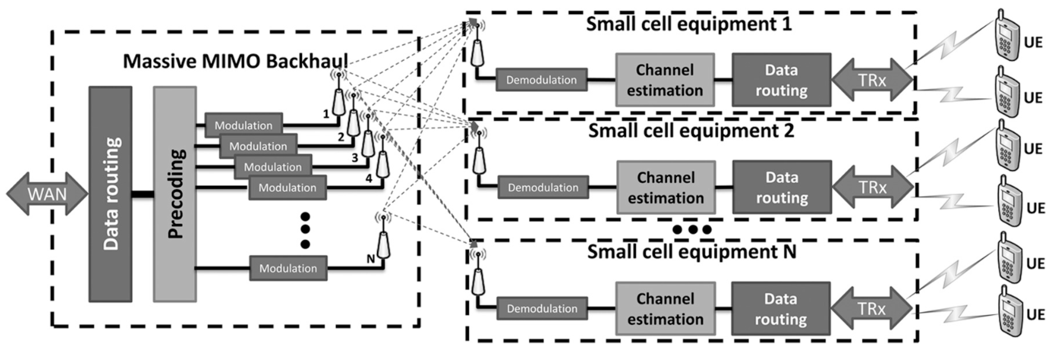
Figure 1. Functional block diagram of massive MIMO system [26].
Electronics 12 00400 g001
Figure 3. Digital beamforming [31].
Electronics 12 00400 g003
Figure 4. Hybrid beamforming [29].
Electronics 12 00400 g004
Figure 5. The effect of beam squint [9].
Electronics 12 00400 g005
Figure 6. Beam squint effect for a phased array antenna using electrical phase shifters operating at frequencies in the range of 10–20 GHz [39].
Electronics 12 00400 g006
Figure 7. Capacity as a function of bandwidth with beam squint (CBS) and without beam squint (CNBS) [41].
Electronics 12 00400 g007
Figure 8. Example of MLE channel estimate using the receiver’s beam squint. There is no beam squint in the transmitter and only one path. No more noise exists. The number of antennas N = 16 [41].
Electronics 12 00400 g008
Figure 9. Series-fed active antenna array [47].
Electronics 12 00400 g009
Figure 10. Point-to-point capacity analysis [49].
Electronics 12 00400 g010
Figure 11. Improvement of capacity for fc = 73 GHz, BW = 2.5 GHz [52].
Electronics 12 00400 g011
Figure 12. Diagram of the proposed subarray design [59].
Electronics 12 00400 g012
Figure 13. Diagram of the proposed analog beamforming design with true time delay lines [59].
Electronics 12 00400 g013
Figure 14. Indoor mmwave software-defined radio (SDR) testbed with a fabricated RF lens for beam squint [61].
Electronics 12 00400 g014
Figure 15. A Sierpinski carpet antenna array with three antenna tiers [65].
Electronics 12 00400 g015
Figure 16. Extensions and variations of the three-tier Sierpinski carpet array [65].
Electronics 12 00400 g016
Figure 17. Near-field system model [67].
Electronics 12 00400 g017
Table 1. Comparison among the main methods used to remove beam squint effect.
ParameterDigital BeamformingAnalog BeamformingCodebook Design
Complexity High complexity Acceptable complexityIncreases the number of phase shifters, which increases the complexity
CostIncreased hardware requirements lead to a high costCompared with their digital counterparts, the costs are much lowerPower and cost rose significantly
Effectiveness Incredibly efficient at correcting the squintHas the potential to decrease the effect of squinting and improve efficiencyAble to significantly lessen the “squint” effect
Table 2. Comparison among various studies conducted in the field of beam squint from 2012 to 2022.
Ref.YearMethodResultsRemarks
[46]2012TTD instead of phase shifters TDD provided good result in overcoming beam squintIncreasing complexity and cost
[47]2012Negative Group Delay CircuitsReduced the beam squint Hardware complexity
[49]2013Three beamforming codebook design schemesReduced the beam squintIncreases the number of phase shifters, which increases power usage and complexity
[50]2016Algorithm that ensures minimum gain for all frequencies and anglesReduced the beam squintGreatly increases the size of codebook, which leads to high latency
[51]2018Alamuti-based beamforming schemeMay successfully fix the beam squint and increase throughput performance.Proposed beam pattern optimization involves eigenvalue and -vector computation, the computation complexity of this scheme grows with the number of antennas
[52]2019Proposed subcarrier-to-beam allocation scheme Exploited beam squint to enhance system performanceHardware complexity since it is applied in digital domain
[53]2019Frequency-division duplex (FDD) massive MIMO-OFDM systems with hybrid analog/digital precoding using a channel estimation schemeProvided more accurate channel estimation than other conventual methodsThe assignment of pilot subcarriers and the design of training beams were not considered
[54]2019Shift-invariant block-sparsity-based compression sensing (CS) algorithmProvided more accurate channel estimation than other conventual methods-
[55]2020Tansec waveform with nonlinear frequency modulation to account for carrier frequency variationBeam direction error was reducedImplemented in digital domain which increase complexity
[56]2021Algorithm for channel estimation using the greatest likelihood criterion in relation to the analog training beam and pilot subcarrier assignmentThe proposed algorithm minimized the mean square error-
[57]2021For RIS-aided wideband (mmwave) communications, phase shift design approaches are used to reduce the impact of beam squint in both LoS and NLoS scenariosBeam squint in such systems was effectively reduced by the proposed phase shift architecture-
[59]2021Virtual subarrays and TDD linesEffective in removing beam squintIncreasing hardware complexity
[60]2021Advanced analog beamforming method proposed based on the Zadoff-Chu (ZC) sequenceThe performance loss caused by the beam squint can be efficiently reduced using the suggested strategy-
[61]2021Three-dimensional electromagnetic analysis softwareClarify how beam squint occurred in RF lens antenna and compare its effect with phased array antenna-
[63]2022Transceiver design based on lens antenna subarray (LAS) and analog sub band filtersResults showed performance enhancementHigher frequencies require high quality filters which increase hardware complexity
[65]2020Create multi-user communication plans that make use of squinting multi-beam properties and small multi-wideband antenna arraysEffective method to exploit beam squint with multi-user systemsSquint-beam-based compact multi-wideband array for millimeter-wave communications
[67]2022Control the beam squint using time delays and using it for localizationEffective method to exploit beam squint in localization-
Disclaimer/Publisher’s Note: The statements, opinions and data contained in all publications are solely those of the individual author(s) and contributor(s) and not of MDPI and/or the editor(s). MDPI and/or the editor(s) disclaim responsibility for any injury to people or property resulting from any ideas, methods, instructions or products referred to in the content.