Abstract
In this article, a dual-frequency microstrip antenna capable of radiating sector beams and rectangular beams is designed. Firstly, the characteristic mode of microstrip antennas is analyzed, and the principle of half-power beam width (HPBW) enhancement of microstrip antennas is studied from the mode combination theory. Studies have shown that when multiple eigenmodes are excited simultaneously at the same frequency point, the radiation modes can be combined to widen the E-plane HPBW. The measurement results indicate that the S11 of the antenna in the two frequency bands is less than −25 dB. In particular, the microstrip antenna E-plane HPBW of the design received a 60° extension. While radiating a wide fan bundle at low frequency points, the HPBW of the E plane extends significantly to 141°. Radiate rectangular beams at high frequency points have an H-plane HPBW beam width of 90° and an E-plane HPBW beam width of 100°.
1. Introduction
With the rapid development of electronic science and technology, the demand for antennas with fan-shaped radiation beam mode is increasing in medical imaging [1], mobile communication base stations [2], satellite communication [3,4], radar [5,6] and other scenes. Traditionally, communication with large angle coverage has always been achieved by employing multiple antennas, each covering only one sector. If the antenna element beam is narrow and wide, a large number of antennas are needed to ensure large coverage. Considering this shortcoming, antenna elements with wide fan-shaped beams have significant advantages in large-coverage communication. Therefore, it is very important to study how to design high-performance sector beam antennas. Microstrip patch antennas are widely used in all aspects of modern applications because of their flat shape, low cost, light weight and ease of manufacture. However, the half-power beam width (HPBW) of traditional microstrip antennas [7,8] is about 90°, and the gain decreases rapidly at low elevation [9], which makes it difficult to meet the demand for wide-angle coverage. Sector beams [10,11] can provide relatively wide azimuth beam widths and have the great advantage of wide signal coverage. Moreover, since sector beam antennas cover a wide range of space, they are commonly used in mobile phones and point-to-point wireless communication systems, as well as base station antennas that form sector coverage in more complex terrain environments such as towns and mountains [12,13]. Therefore, it is very important to study how to design high-performance sector beam antennas.
In [14,15,16], a plurality of patches is used to form an antenna array, and the larger metal ground has a broad beam mode to achieve the purpose of expanding the beam width. The presence of numerous units vastly augments the dimension of the antenna, and at the same time, the design cost is greatly increased. In [16,17,18], vertical metal walls are loaded to generate vertical induced currents; however the metal walls introduced increase the height of these antennas, thus breaking the low-profile characteristics of planar antennas. At the same time, antennas moderately increase the gain. In [7,19,20], the work proposes a new method for beam width improvement by using several radiation patterns of a microstrip patch antenna (MPA). However, they are always subjected to monopole radiation patterns or high cross-polarization levels. In [21,22], the antenna obtains a beam width of more than 120° by loading a folded dipole. However, these methods all have high profile heights, which hinders their wide application in modern communication systems.
In the previous antenna design with improved beam width, the sector beam can only receive the transmitted signal from a specific angle direction and provide a wide range of signal angle coverage but cannot accept the signal from other angles. Therefore, we propose a dual-frequency microstrip antenna with both a sector beam and a rectangular beam. Rectangular beams have the advantage of fan-shaped beams, which have the radiation characteristics of a flat shape and can receive signals from other angular directions while providing a large range of signal angle coverage.
Based on the above discussion, a method of widening the beam width of low profile dual-frequency antennas by using the combination of characteristic modes is proposed. First, characteristic modal analysis (CMA) [23,24,25] is performed on the rectangular patch, and then the required mode is excited to resonate at the same frequency point. Finally, the lower band E-plane HPBW is successfully broadened, while the rectangular beam is radiated in the upper band. The measurement results show that the HPBW can reach 141°, and the maximum gain is 8.2 dBi for the sector beam radiated at low frequency. The HPBW can reach 100°, and the maximum gain is 5.7 dBi for the rectangular beam radiated at high frequency.
2. Geometric Shape and Design Principle of the Proposed Antenna
2.1. Theory of Characteristic Modes
The eigenmode theory is an analytical method based on the method of moments (MoM) for analyzing the inherent properties of electromagnetic structures. The core problem is to work out the broad sense eigenvalue problem, which involves finding the eigenvectors and eigenvalues that satisfy certain conditions.
where R and X are real symmetric operators, and Jn is the characteristic current. The current is extended across the conductor to the characteristic current as a RWG basis function. An RWG basis function is a kind of basis function defined on the adjacent plane triangle patch proposed by Rao, Wilton, and Glisson in 1982, also known as the generalized ridge basis function.
Then, after derivation,
where the coefficient αn represents the significance of the eigenvalue in the total current and is referred to as the modal weighting coefficient (MWC). The denominator is only related to the eigenvalue λn of the mode.
The commonly used parameters in Eigenmode analysis are excitation coefficient Vn, mode factor MS, and characteristic angle (CA), and their expressions are, respectively:
where Vn is the modal excitation coefficient (MEC), and Ei is the incident electric field, which is related to factors such as the excited mode, position, amplitude, and phase.
It can be seen from (5) that the value range of MS is between 0 and 1. When MS approaches 1, the mode is closer to the resonance state; conversely, this indicates that the mode is far from resonance, which makes it difficult to excite and effectively radiate.
CA represents the phase difference between the modal characteristic current and the homologous characteristic electric field. When CA is 180°, it indicates that the mode is in resonance.
2.2. Principle of Feature Pattern Combination
We know that due to the larger limitations on the ground, the microstrip antenna itself has a weak radiation ability on the back side, so it has a directional radiation pattern pointing to the normal direction. The radiant power density decreases with increasing θ, and the gain is relatively low near the equatorial angle. In the higher-order mode of the microstrip antenna, there is a heart-shaped radiation pattern with a maximum radiation direction of ±45°. The vertical direction has zero radiation (θ = 0°), and the 45° direction has the greatest radiation capacity (θ = ±45°). When the microstrip antenna simultaneously excites a directional radiation pattern that points to the normal direction and a radial pattern that has a heart shape, if the two modes are gradually close together, they will affect each other, and their modes will be combined so that their directional patterns will be superimposed on each other. The results are shown in Figure 1 [21].
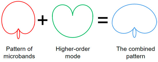
Figure 1.
The principle of enhanced HPBW.
2.3. The Structure Configuration and Evolution Process of the Antenna
Figure 2 and Table 1 respectively show the specific shape and detailed parameters of the proposed dual-frequency microstrip antenna. The antenna is printed on a single-layer grounded F4BM220 substrate with a profile height of 2 mm, dielectric constant r = 0.02, and loss angle tangent tan δ = 0.0009. Specifically, the antenna is modified on a rectangular patch and four horizontally oriented parasitic metal strips, which are then connected to the rectangular radiant patch by eight short microstrip lines. Four metal posts are then added to the four metal strips to make the patch and floor shorter. Two symmetrical slots are etched into the radiant patch, and two metal posts are added next to the slots. The antenna was finally connected to the radiator by a microstrip wire and fed through a 50ΩSMA feed welded to the microstrip wire, and then the designed antenna was extensively studied using HFSS 15.0.
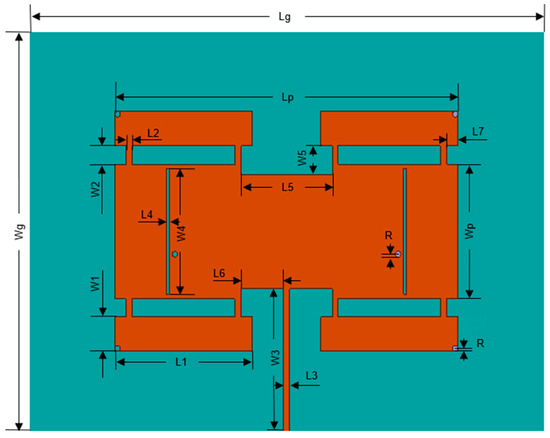
Figure 2.
The developed dual-frequency antenna is configured.

Table 1.
Dimension parameter (Unit: mm).
As is well known, the microstrip antenna in Figure 3a has a narrow HPBW in the TM10 mode. Meanwhile, non-transverse radiation patterns can be generated at a higher TM12 mode [11]. In order to solve these problems and generate the required wide HPBW, we take the following measures: (1) Introduce the horizontal metal bands as shown in Figure 3b, and add four horizontal metal bands to the rectangular radiation patch to stimulate the characteristic modes so that the rectangular patch is not excited. (2) By connecting the rectangular radiation patch with the metal band in Figure 3c, the original radiation characteristics are changed, the characteristic modes in the lower frequency band are moved to the working frequency band, and the radiation modes are combined to realize the purpose of broadening HPBW. (3) Load the metal into the four corner holes in Figure 3d, similarly move the characteristic modes in the lower frequency band to the working frequency band, and cut linear slots on the patch to enhance the interaction between various modes and achieve rectangular beam radiation. Through these arrangements, the antenna design is improved at the same time, namely with thin, dual frequency, wide fan beam, wide E-plane HPBW and flat top radiation beam.
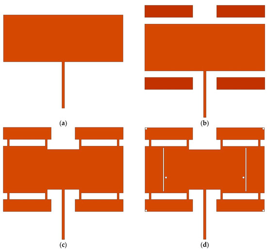
Figure 3.
The evolution process of wide E planar HPBW microstrip antenna is proposed. (a) Conventional microstrip antennas. (b) Conventional microstrip antennas and metal strips. (c) Antenna after connection. (d) Antenna for loading through metal holes and load slots.
Figure 4 simulates patches A-D for |S11|. It can be found that patch A has only one resonant frequency in the 4 to 6 GHz band, and in the lower frequency range, |S11| has a decreasing trend, and there may be a resonant frequency. The introduction of metal bands in patch B does not have much effect on the original resonant frequency, and the purpose of introducing metal bands is to stimulate new characteristic modes. In patch C, by connecting the rectangular patch to the metal strip with a microstrip line, it can be found that the original resonant frequency is slightly shifted to the lower frequency, and the resonant frequency in the lower frequency band is gradually moved to the working frequency band. In patch D, the loading of the short circuit through the hole stimulates the drastic change of the first vibration frequency, making it gradually close to the second and third resonant frequencies. At the same time, the linear gap will help eliminate the notch band in the working frequency band, so that multiple modes can influence each other to produce a combined mode. A detailed characteristic mode analysis is presented in the next section.
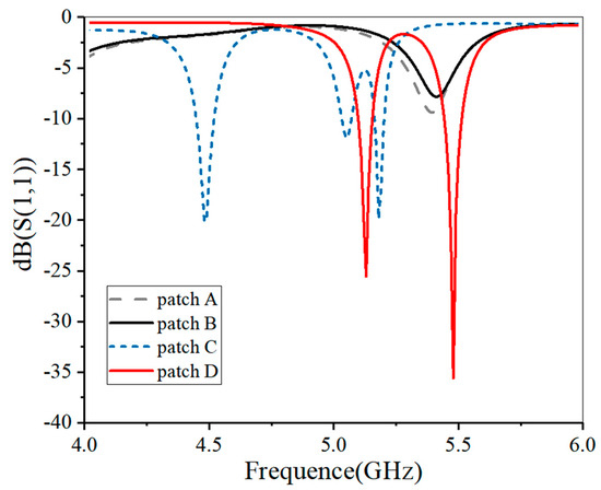
Figure 4.
Simulated |S11| of patch A-D.
3. Design of Dual-Frequency Microstrip Antenna
3.1. Realization of Wide Fan Beam
We know that rectangular patches have many typical characteristic modes. For research on how the patch works, CST Studio Suite 2018 was used to analyze its modal significance and characteristic angles. In order to realize the sector radiation beam, the design was improved on the basis of rectangular patch, and the electromagnetic field of vector superposition was generated in the far field by simulating an array, so as to realize the compression of the radiation beam in space and finally realize the sector beam. Figure 5 and Figure 6 show the characteristic angles and modal significance of the 10 modes of the rectangular patch in Figure 3a.
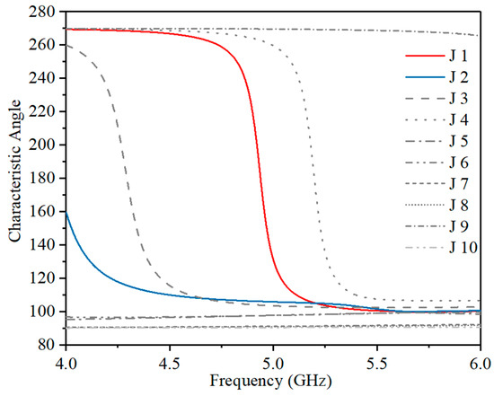
Figure 5.
Characteristic angle of patch A.
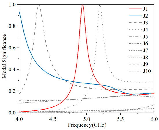
Figure 6.
Modal significance of patch A.
When the feature angle is 180° or the modal significance is 1, the feature modes are excited. It can be seen from Figure 5 and Figure 6 that patch A excites four feature modes in the operating frequency band 4 to 6 GHz, namely J1, J2, J3 and J4. It can be found that the feature angle and the maximum modal significance of mode J2 are beyond the operating frequency band, so mode J2 is excited in the lower frequency range, while other modes are excited in the higher frequency.
In order to understand the physical meaning of the feature map in more detail, we plot the characteristic current and radiation direction of the rectangular patch in Figure 7. The results show that the current of mode J2 is mainly concentrated on the left and right sides and has the same direction current characteristics, resulting in a nearly perfect main lobe. The radiation pattern of J2 is a fan-shaped main lobe, which is due to the large width of the selected rectangular patch, resulting in vector superposition of electromagnetic waves in far-field radiation, thus achieving beam compression. Modes J1, J3 and J4 are all high-order modes, in which the current of mode J1 is mainly concentrated in the upper and lower ends, resulting in the splitting of the radiation pattern due to the reverse mode current, resulting in a huge side lobe, while the current of mode J3 is mainly concentrated in the left and right sides, resulting in the splitting of the pattern due to the reverse current characteristics. Mode J4 has both the left and right sides and the upper and lower ends of the current characteristics, although the left and right sides of the current are the same as in mode J1, but because the upper and lower ends of the reverse current produce a huge side lobe, and the main lobe is almost non-existent. According to Formula (4) and mode extension theory, these unacceptable patterns may affect the overall radiation pattern, and, therefore, they should be removed from the frequency band.
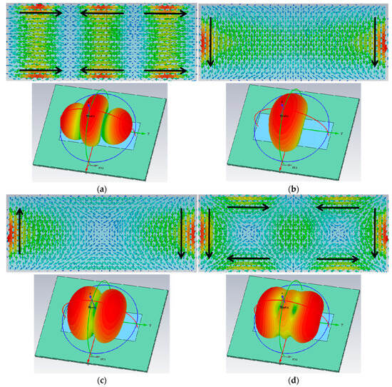
Figure 7.
Modal current and radiation patterns for patch A. (a) J1. (b) J2. (c) J3. (d) J4.
According to the mode combination theory proposed in the second part, the beam width can be widened when the directional radiation mode is combined with the heart-shaped radiation mode. None of the four modes excited by patch A in Figure 7 can achieve wider HPBW through mode combination. As a result, new feature patterns need to be stimulated, which can be challenging for rectangular patches. We know that choosing the right feeding position can effectively stimulate the desired pattern. However, this design uses microstrip line side feeds, so some manipulation is required to excite the new mode.
In this paper, a metal strip is introduced to generate a new current path, which excites a new characteristic pattern. The modal significance of metal strip patch B is shown in Figure 8. In the frequency band of 4 to 6 GHz, patch B excites A total of 8 modes, among which the modes (J1 to J3) are consistent with that of piece A, so there is no more analysis. We will focus on the five remaining modes of patch B (J4 to J8).
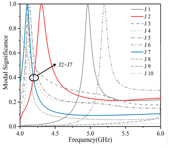
Figure 8.
Modal significance of patch B.
Figure 9 plots the corresponding mode current and radiation directions of the modes studied by patch B at resonant frequencies. It can be found that the mode current J4 in Figure 9a is mainly concentrated on the metal strip. Due to the opposite current paths on the left and right symmetric metal bands, a heart-shaped radiation pattern radiating in the direction of ±Y axis 45° is generated. The mode current J5 in Figure 9b is concentrated at the upper and lower ends of the metal strip and the rectangular patch, respectively, and the current on the metal strip and the rectangular patch is in the same direction, resulting in a directional radiation pattern. The current of mode J6 in Figure 9c is mainly concentrated on the rectangular patch, which is exactly the same as the current characteristics of mode J4 in Figure 7d and also generates a huge sidelobe, while the main lobe is almost non-existent. The mode current J7 in Figure 9d is also mainly concentrated on the metal strip, but the current paths on the upper and lower symmetric metal strip are reversed, resulting in a heart-shaped radiation pattern radiating 45° along the ±X axis. The mode current J8 in Figure 9e is also mainly concentrated on the metal strip, where the current path on the upper and lower symmetric metal strips is opposite, and the current path on the left and right symmetric metal strips is opposite, forming the characteristics of quadrupole radiation. It can be found that both modes J4 and J7 produce the heart-shaped pattern shown in Figure 1, but mode J2 radiates a fan beam in the xoz plane. Therefore, only the combination of mode J7 and mode J2 can effectively extend the E-plane HPBW. As can be seen from Figure 8, the modal significance of the combined mode (J2 + J7) is 0.4, and its combination effect is not ideal. Only when the modal significance of the combined mode is greater than 0.7 can the two modes be effectively combined. It is recommended to connect the metal strip and the patch with a microstrip line to make the J2 mode and J7 mode resonate in the same frequency band.
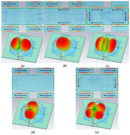
Figure 9.
Modal current and radiation patterns of patch B. (a) J4. (b) J5. (c) J6. (d) J7. (e) J8.
Figure 10 and Figure 11 show the modal significance of patch C and the modal current and radiation patterns for the corresponding modes. The modes studied in patch C excite a total of six modes (J1 to J4, J6, J7) at resonant frequencies. As shown in Figure 11a, the longitudinal current of the modal current J1 in patch C does not change significantly from the longitudinal current of the modal current J2 in Figure 7b. In Figure 9d, the mode current J7 changes from the horizontal current on the metal strip to the toroidal portion of the mode current J1 flowing along the rectangular slot in Figure 11a. Thus, by combining the J2 mode and the J7 mode, the HPBW was successfully widened from 80° to 141°. It can be found that the sector beam in Figure 11a is significantly widened compared to the sector beam in Figure 7b.
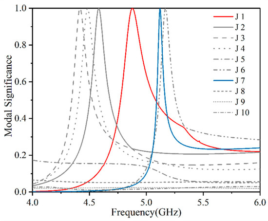
Figure 10.
Modal significance of patch C.
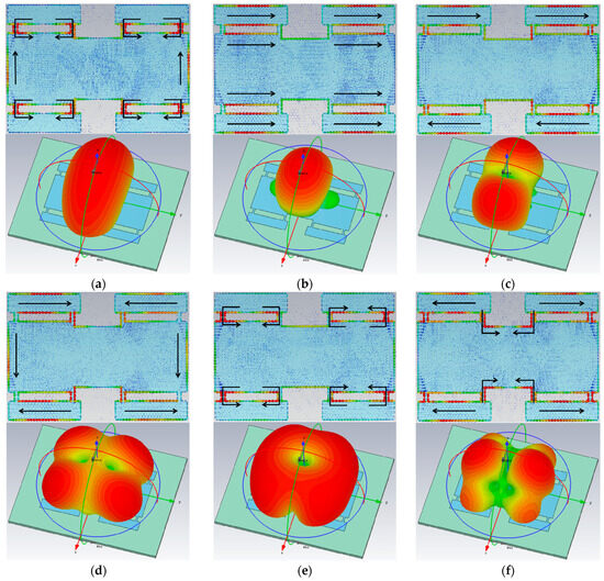
Figure 11.
Modal current and radiation patterns of patch C. (a) J1. (b) J2. (c) J3. (d) J4. (e) J6. (f) J7.
To sum up, through the combination of modalities, radiation patterns with wider HPBW can be achieved. The only challenge is to excite both required radiation modes at the same time. Therefore, the antenna structure should be changed so that the two modes resonate at the desired frequency. In this section, we propose a wide fan beam microstrip antenna using a mode combination approach. Through these arrangements, some improved performance of the designed antenna is obtained at the same time. The H-plane HPBW is about 50°, and the E- plane HPBW is successfully widened from 80° to 141°.
3.2. Realization of Flat Top Radiant Beam
On the basis of existing frequency points, in order to design a dual-frequency microstrip antenna with rectangular radiation mode, we reanalyzed some important characteristic modes of patch C, as shown in Figure 10 and Figure 11. As can be seen, mode J6 produces a similar conical pattern with a radiating zero in the center. According to the mode combination theory presented in Section 2, if you want to use the mode combination theory to form a rectangular radiation pattern, here you need a directional radiation mode (for example, mode J2) to fill the radiation zero of mode J6. A patch D loaded with symmetric linear slots and through-metal holes is proposed, and its modal significance and radiation diagram are shown in Figure 12.
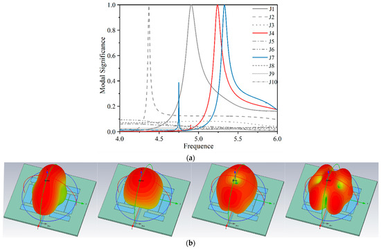
Figure 12.
(a) Modal significance of patch E. (b). Radiation modes of patch E (J1, J2, J4, J7).
Figure 12a shows the modal significance of loading a symmetric linear slot on patch D and passing through the metal pass hole. It is found that the frequency of mode J1 does not change significantly after loading through the metal pass hole, because the metal pass hole is located at the zero potential of the J1 mode electric field, which does not cause a drastic change in the electric field and does not cause a change in impedance. Figure 12b shows the four modes (J1, J2, J4 and J7) excited by patch D. The radiation pattern of J1 has side lobes, which is caused by the interference of the etched slot, but it does not affect the main radiation pattern, which is acceptable. It is found that mode J4 is similar to the conical radiation mode, the z-axis direction is the radiation zero, and mode J7 has two radiation zero points, respectively located in the direction of ±30° of the Y-axis, and combining them can give a rectangular radiation pattern. Modes J4 and J7 are exactly what we need. As can be seen from Figure 12a, the modal meaning of the combined mode (J4 + J7) is about 0.7, and the two modes can be excited at the same time, so the combined mode has a good modal meaning.
In summary, according to the principle of modal combination, we carry out the characteristic modal analysis of the antenna. Then through the above series of arrangements, the rectangular radiation beam is successfully designed, and the performance of the designed antenna is improved. Therefore, this paper presents a thin dual-frequency microstrip antenna using a modal combination method. A sector radiation beam of 141° HPBW in the E plane is obtained in the low frequency band, and rectangular radiation beams of 100° H-PBW in the E plane and 90° HPBW in the H plane are obtained in the high frequency band.
4. Parameter Analysis
In Figure 13, the change process of the S-parameter after loading metal through holes and slots in Figure 3c,d is plotted. It is found that there are three resonant frequencies in the operating band when loading without metal through holes, and the first frequency is not required, so it needs to be moved out of the operating band without affecting the position of the second frequency. With the increase in the number of through-holes, the first resonant frequency gradually moves to the high frequency, the position of the second resonant frequency has almost no effect, and the third resonant frequency moves slightly to the high frequency, which is because the position of the metal through-hole loading is located at the low potential of the electric field of the second resonant frequency, which will not cause a drastic change in impedance. When the number of metal pieces through holes is gradually increased to four, the first resonant frequency moves out of the operating frequency. By etching the slot, the current feature is disturbed so that a new frequency is generated between the two frequencies, and then two metal pieces through holes are loaded next to the slot so that the newly generated frequency point and the resonant frequency point on the right side are fused to produce a rectangular radiation beam.
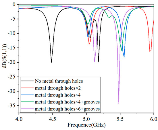
Figure 13.
Simulate the |S11| loaded with metal through holes and slots in Figure 3c,d.
5. Physical Test Verification
In order to verify the above works, the final production and measurements of the proposed antenna, the use of the Ceyear 3672B-S vector network analyzer measured the process of making the antenna |S11|, and the map in Figure 14 shows that they have been obtained with good impedance matching (|S11| > 25 dB). At the same time, its overall thickness is maintained around 0.03λ0, thus maintaining the ideal low-profile performance.
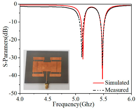
Figure 14.
Simulation and measurement of the proposed dual-band wide.
Then, the radiation pattern of the proposed MPA was measured by means of an anechoic chamber. Figure 15 shows the antenna’s simulated and measured radiation directions at 5.13 and 5.48 GHz, respectively. It can be seen that the measured results agree well with the simulation results, and the radiating sector beam is successfully realized at 5.13 GHz with a half-power beam width of about 141° in the E-plane and 32° in the H-plane, and a gain of about 8.2 dBi. The rectangular beam radiated at 5.48 GHz has an E-plane half-power beam width of about 100° and an H-plane half-power beam width of about 90°, with a gain of about 5.7 dBi. Small differences between simulation and measurement are due to manufacturing, installation and test errors. Finally, the performance comparison of the developed low-profile dual-band microstrip antenna prototype is shown in Table 2. The developed dual-frequency microstrip has its unique advantages, not only radiating a sector beam pattern at the first frequency point but also offering a unique rectangular beam pattern at the second frequency point and higher gain performance within a compact overall size limit.
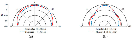
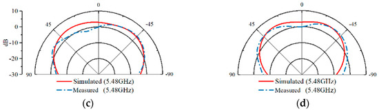
Figure 15.
Simulated and measured radiation patterns of the proposed dual-band wide-HPBW MPA under dual resonance. (a). E-plane. (b). H-plane. (c). E-plane. (d). H-plane.
Table 2.
Comparison with previous wide-HPBW antennas.
6. Conclusions
In this article, a low-outline dual-frequency microstrip antenna using a combination of feature modes is proposed. First, the characteristic modes of the rectangular patch are analyzed, the required directional basic modes and heart-shaped high-order modes are excited and combined, and the beam width of the E-plane HPBW is effectively widened. The actual measurement results show that a sector beam with a gain of 8.2 dbi is formed at 5.13 GHz, and its E-HPBW beam width is 141° and H-HPBW beam width is 32°. A rectangular beam with a gain of 5.7 dBi is formed at 5.48 GHz, and its E-HPBW beamwidth is 100° and H-HPBW beam width is 90°. The proposed dual-frequency microstrip antenna has the capability of radiating sector beam and rectangular beam at the same time, maintains wide azimuth coverage in both frequency bands, and has excellent high resolution and high gain performance. The simulation results agree well with the measured results, which shows the feasibility and effectiveness of the design. Therefore, the proposed dual-frequency microstrip antenna can be used in wireless communication systems with wide-angle coverage requirements.
Author Contributions
Conceptualization, X.-P.L. and M.-M.L.; Methodology, X.-P.L. and A.-X.Z.; Software, X.-P.L. and Q.-Q.S.; Validation, Q.-Q.S. and W.L.; Formal analysis, M.-M.L. and J.-F.J.; Investigation, X.-P.L., M.-M.L. and W.L.; Data curation, W.L. and A.-X.Z.; Writing—original draft, M.-M.L.; Writing—review & editing, X.-P.L. and W.L.; Supervision, X.-P.L.; Funding acquisition, X.-P.L. and W.L. All authors have read and agreed to the published version of the manuscript.
Funding
This research was supported by the Research Practice Project of Higher Education Teaching Reform in Henan Province (2021SJGLX204Y), the Key Scientific Research Projects of Colleges and Universities in Henan Province (22B510008), and the Doctoral Scientific Research Start-up Foundation of Henan Normal University (5101239170009).
Data Availability Statement
Not applicable.
Conflicts of Interest
The authors declare no conflict of interest.
References
- Hay, S.G.; Archer, J.W.; Timms, G.P.; Smith, S.L. A beam-scanning dual-polarized fan-beam antenna suitable for Millimeter wavelengths. IEEE Trans. Antennas Propag. 2005, 53, 2516–2524. [Google Scholar] [CrossRef]
- Cui, Y.; Li, R.; Fu, H. A Broadband Dual-Polarized Planar Antenna for 2G/3G/LTE Base Stations. IEEE Trans. Antennas Propag. 2014, 62, 4836–4840. [Google Scholar] [CrossRef]
- Eom, S.Y.; Son, S.H.; Jung, Y.B.; Jeon, S.I.; Ganin, S.A.; Shubov, A.G.; Tobolev, A.K.; Shishlov, A.V. Design and Test of a Mobile Antenna System with Tri-Band Operation for Broadband Satellite Communications and DBS Reception. IEEE Trans. Antennas Propag. 2007, 55, 3123–3133. [Google Scholar] [CrossRef]
- Ferrero, F.; Luxey, C.; Jacquemod, G.; Staraj, R. Dual-band circularly polarized microstrip antenna for satellite applications. IEEE Antennas Wirel. Propag. Lett. 2005, 4, 13–15. [Google Scholar] [CrossRef]
- Menzel, W.; Moebius, A. Antenna Concepts for Millimeter-Wave Automotive Radar Sensors. Proc. IEEE 2012, 100, 2372–2379. [Google Scholar] [CrossRef]
- Yi, Z.; Zhange, R.; Xu, B.; Chen, Y.; Zhu, L.; Li, F.; Yang, G.; Luo, Y. A Wide-Angle Beam Scanning Antenna in E-plane for K-band Radar Sensor. IEEE Access 2019, 7, 171684–171690. [Google Scholar] [CrossRef]
- Liu, N.; Zhu, L.; Liu, Z.; Liu, Y. Dual-Band Single-Layer Microstrip Patch Antenna with Enhanced Bandwidth and Beamwidth Based on Reshaped Multiresonant Modes. IEEE Trans. Antennas Propag. 2019, 67, 7127–7132. [Google Scholar] [CrossRef]
- Garg, R.; Bhartia, P.; Bahl, I.; Ittipiboon, A. Microstrip Antenna Design Handbook; Artech House: Boston, MA, USA, 2001. [Google Scholar]
- Yang, G.; Li, J.; Wei, D.; Zhou, S.; Yang, J. Broadening the beam-width of microstrip antenna by the induced vertical currents. IET Microw. Antennas Propag. 2018, 12, 190–194. [Google Scholar] [CrossRef]
- Yu, C.; Li, E.S.; Jin, H.; Cao, Y.; Su, G.; Che, W.; Chin, K. 24 GHz Horizontally Polarized Automotive Antenna Arrays with Wide Fan Beam and High Gain. IEEE Trans. Antennas Propag. 2019, 67, 892–904. [Google Scholar] [CrossRef]
- Cho, H.; Lim, S.; Jo, H.; Chae, S.; Yu, J. Microstrip-line type bruce array antenna with wide fan beam and high gain. J. Electromagn. Waves Appl. 2021, 35, 813–821. [Google Scholar] [CrossRef]
- Chou, H.; Kuo, L.; Chou, S. Design of Shaped Reflector Antennas for the Applications of Outdoor Base Station Antennas in LTE Mobile Communications. Radio Sci. 2018, 53, 1023–1038. [Google Scholar] [CrossRef]
- Wen, S.; Xu, Y.; Dong, Y. Low-Profile Wideband Omnidirectional Antenna for 4G/5G Indoor Base Station Application Based on Multiple Resonances. IEEE Antennas Wirel. Propag. Lett. 2021, 20, 488–492. [Google Scholar] [CrossRef]
- Li, M.; Pu, L.; Tang, M.; Zhu, L. A Single-Layer Dual-Band Array at Low-Frequency Ratio with Concurrent Broad Fan Beam and Narrow Pencil Beam. IEEE Trans. Antennas Propag. 2022, 70, 3354–3365. [Google Scholar] [CrossRef]
- Kim, S.; Choi, J. Quasi-Yagi Slotted Array Antenna with Fan-Beam Characteristics for 28 GHz 5G Mobile Terminals. Appl. Sci. 2020, 10, 7686. [Google Scholar] [CrossRef]
- Yang, G.; Li, J.; Zhou, S.G.; Qi, Y. A Wide-Angle E-Plane Scanning Linear Array Antenna with Wide Beam Elements. IEEE Antennas Wirel. Propag. Lett. 2017, 16, 2923–2926. [Google Scholar] [CrossRef]
- Chen, L.; Zhang, T.; Wang, C.; Shi, X. Wideband Circularly Polarized Microstrip Antenna with Wide Beamwidth. IEEE Antennas Wirel. Propag. Lett. 2014, 13, 1577–1580. [Google Scholar] [CrossRef]
- Yang, W.J.; Pan, Y.M.; Zheng, S.Y. A Low-Profile Wideband Circularly Polarized Crossed-Dipole Antenna with Wide Axial-Ratio and Gain Beamwidths. IEEE Trans. Antennas Propag. 2018, 66, 3346–3353. [Google Scholar] [CrossRef]
- Liu, N.; Gao, S.; Fu, G.; Zhu, L. A Low-Profile Dual-Band Patch Antenna with Simultaneous Wide Beamwidth and High Gain by Using Multiresonant Modes. IEEE Antennas Wirel. Propag. Lett. 2021, 20, 813–817. [Google Scholar] [CrossRef]
- Ko, S.; Lee, J. Hybrid Zeroth-Order Resonance Patch Antenna with Broad E-Plane Beamwidth. IEEE Trans. Antennas Propag. 2013, 61, 19–25. [Google Scholar] [CrossRef]
- Li, Y.; Luk, K. A Linearly Polarized Magnetoelectric Dipole With Wide H-Plane Beamwidth. IEEE Trans. Antennas Propag. 2014, 62, 1830–1836. [Google Scholar] [CrossRef]
- Wong, H.; Mak, K.-M.; Luk, K.-M. Wideband shorted bowtie patch antenna with electric dipole. IEEE Trans. Antennas Propag. 2008, 56, 2098–2101. [Google Scholar] [CrossRef]
- Li, T.; Chen, Z.N. A Dual-Band Metasurface Antenna Using Characteristic Mode Analysis. IEEE Trans. Antennas Propag. 2018, 66, 5620–5624. [Google Scholar] [CrossRef]
- Zhao, S.; Li, X.; Chen, Y.; Zhao, W.; Qi, Z. A Wide-Beam Metasurface Antenna Using Pattern Combination of Characteristic Modes. Appl. Comput. Electromagn. Soc. J. 2022, 37, 41–49. [Google Scholar] [CrossRef]
- Lin, F.H.; Chen, Z.N. Low-Profile Wideband Metasurface Antennas Using Characteristic Mode Analysis. IEEE Trans. Antennas Propag. 2017, 65, 1706–1713. [Google Scholar] [CrossRef]
Disclaimer/Publisher’s Note: The statements, opinions and data contained in all publications are solely those of the individual author(s) and contributor(s) and not of MDPI and/or the editor(s). MDPI and/or the editor(s) disclaim responsibility for any injury to people or property resulting from any ideas, methods, instructions or products referred to in the content. |
© 2023 by the authors. Licensee MDPI, Basel, Switzerland. This article is an open access article distributed under the terms and conditions of the Creative Commons Attribution (CC BY) license (https://creativecommons.org/licenses/by/4.0/).