Article

Tuning of PID/PIDD2 Controllers for Second-Order Oscillatory Systems with Time Delays

1
School of Control & Computer Engineering, North China Electric Power University, Beijing 102206, China
2
School of Electrical and Control Engineering, North China University of Technology, Beijing 100144, China
*
Author to whom correspondence should be addressed.
Electronics 2023, 12(14), 3168; https://doi.org/10.3390/electronics12143168
Submission received: 12 June 2023 / Revised: 13 July 2023 / Accepted: 17 July 2023 / Published: 21 July 2023

Abstract

:
PID control is the longest history and the most vital basic control mode that has been widely applied in the production process. The oscillatory dynamics of the process have various features, and parameter tuning is complicated. To reduce the complexity of the parameter tuning process and improve the performance of the system, in this research, we propose a new tuning method for the PID/PIDD2 controllers for second-order oscillatory systems with time delays under the constraint of certain robustness. In comparison to existing PID for second-order oscillatory systems with time delays, simulation findings demonstrate that the tuning method of the proposed PID/PIDD2 controllers trades off robustness and disturbance rejection performance.

1. Introduction

1.1. Background

Proportional-integral-derivative (PID) control is the most vital basic control mode that has been widely applied in the production process [1]. The principal reason is that it only needs three adjustable parameters, and does not require the exact information of the system [2]. Because of this, the majority of research in the field of process control has concentrated on PID control [3,4,5,6,7].
The underdamped systems are commonly found in practical applications, like bridge cranes control systems [8], pipeline pressure control systems [9,10], robot control systems [11], load frequency control systems [12,13], and vibration control systems [14,15]. However, the systems mentioned above require particular attention since their step response exhibits oscillatory behavior. Moreover, for the underdamped system, the conflict between rapidity and overshoot cannot be resolved [16,17]. Therefore, to obtain satisfactory control results, that is, the closed-loop response of the system without or with a relatively small overshoot [18] and the shortest possible stabilization time, we need to research the appropriate controller parameter tuning method for underdamped oscillatory systems.

1.2. Analysis of the Existing Literature

To the best of our knowledge, extensive research on oscillatory systems still adopts PID. Ho et al. [19] studied the relationship between the control parameters and specifications (the gain and phase margin) and obtained the PID controller parameter values through the method of specifying specifications, as it is difficult to select suitable gain and phase for different underdamped systems. Wang et al. [20] provided a simple calculation formula for the oscillatory system based on the traditional root locus analysis approach, the process of solving equations is complicated. Shen [21] adopted the fuzzy neural network approach to tune the PID controller for the underdamped oscillatory system. The training speed of the neural network is slow and the calculation amount is large, so it is not convenient to implement. Skogestad [22] modified the integral form of the internal model control (IMC)-PID tuning criterion and obtained the simple tuning formula, wherein the controller parameters met the requirements of IAE, TV, and robustness. The performance of this method does not show a significant advantage over currently used control methods. Huang et al. [23] presented an inverse-based synthesis PID controller design method, and the robustness of this method is analyzed via the gain and phase margin; this method also needs to select the appropriate gain and phase. Maclaurin performed the tuning of the PID controller based on [24] for the first-order process with a dead-time (FOPDT) and second-order process with a dead-time (SOPDT) process. Chen et al. [25] designed a PID controller based on direct synthesis and disturbance closed-loop transfer function to reject disturbance, and obtained the tuning formula; this method has both large and small robustness and ITAE. Ho et al. [26] used an orthogonal simulated annealing (OSA)-based approach optimal fuzzy neural network model to tune PID controller parameters to minimize the mean tracking error and satisfy a robustness constraint for the underdamped oscillatory system; this method also suffers from high computational complexity. Malwatkar et al. [27] derived the PID controller tuning procedure for higher-order oscillatory systems through the reduced order of the model. For this method for the moderate oscillatory system, the disturbance response is still oscillating and not eliminated. Eriş et al. [28] proposed PID tuning rules based on direct digital control for the SOPDT system and obtained a fast response from the closed loop system without overshooting. This method uses a discrete controller and is suitable for critically damped systems. Kurokawa et al. [29] discussed the relationship between set point tracking performance and robust stability, and provided an optimal PID design method for the SOPDT system. The method was designed using the maximum value of the sensitivity function ( M s ) and the PID parameters were decided by IAE. However, no clear tuning formula is given. Other studies on oscillatory systems will not be listed here.
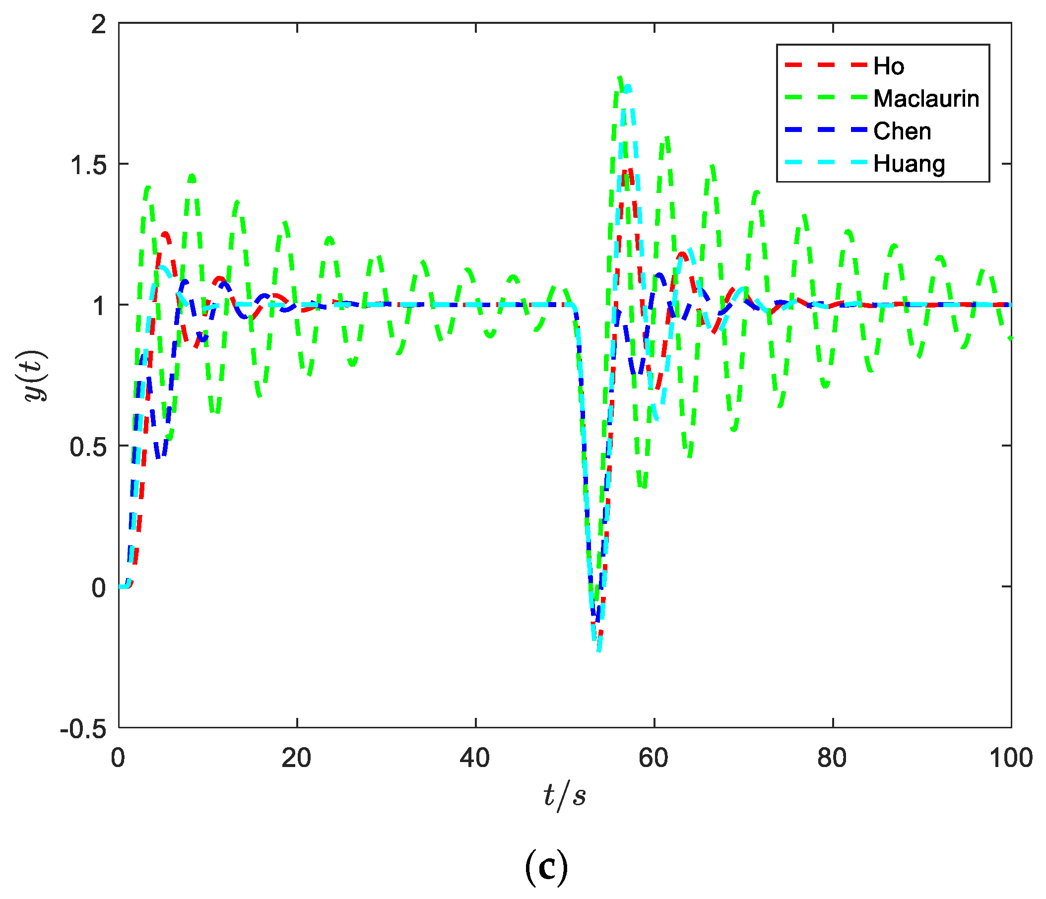
Consider the four methods (gain and phase margin-based PID [19], direct synthesis PID [23], closed-loop specified (CS)-PID [25], and IMC-PID [30]) mentioned above as examples; these four tuning methods are typical, so they are examined as a comparison. the closed-loop system robustness ( ε ) [31], disturbance rejection performance (the integral of time and absolute error (ITAE)), and the step response obtained for the underdamped SOPDT systems are shown in Table 1 and Figure 1. Since the range of the magnitude of ITAE over the entire time horizon is large, it is represented in terms of dB (20lg(ITAE)) in Figure 1. From Table 1 and Figure 1, we observe:
(1)
The robustness value and ITAE of Maclaurin’s method [30] are apparently larger than the other three methods; thus, it is very sensitive to unmodeled dynamics. The step response of Maclaurin’s method is also seriously oscillatory.
(2)
Although the robustness value of Ho et al. [19] is smaller than Huang et al. [23], the ITAE’s of both are similar. Chen et al. [25] has both large and small robustness and ITAE.
(3)
Maclaurin’s and Huang’s methods are based on the model inverse; for the moderate oscillatory system (Figure 1c), the disturbance response is still oscillating and not eliminated. At the same time, Ho et al.’s approach can be included in addition to the above problems and also needs to select a suitable gain and phase for different underdamped systems, which is not conducive to practical engineering practice. The step response of Chen et al. eliminates the oscillation; however, from the point of view of both disturbance resistance and robustness, it is not optimal.
Remark 1. 
The process of calculating the performance indices ITAE and  ε  in Figure 1 is based on (4) and (7).

1.3. Motivation and Contribution of the Paper

From the previous discussion, it is necessary to find a new optimal PID controller design method that can trade-off between robustness and disturbance rejection performance for underdamped oscillatory systems, and this paper will first derive a PID tuning method for such systems.
As far as we know, proportional integral double derivative (PIDD2) can be used to improve the performance of the conventional PID [32,33]. The application of the PIDD2 controller in the voltage and frequency control of power systems has achieved satisfactory robustness [34,35]. Even though the parameter tuning of the PIDD2 controller has been studied in the literature [36,37,38], very little was found in the literature [39] on the question of PIDD2 controller for oscillatory systems. In this paper, the tuning formula of the PIDD2 controller for the underdamped oscillatory with time delays system will also be derived. The tuning formula of the PID/PIDD2 controller parameters are obtained by using the optimization algorithm while satisfying the robustness constraint and minimizing the ITAE.
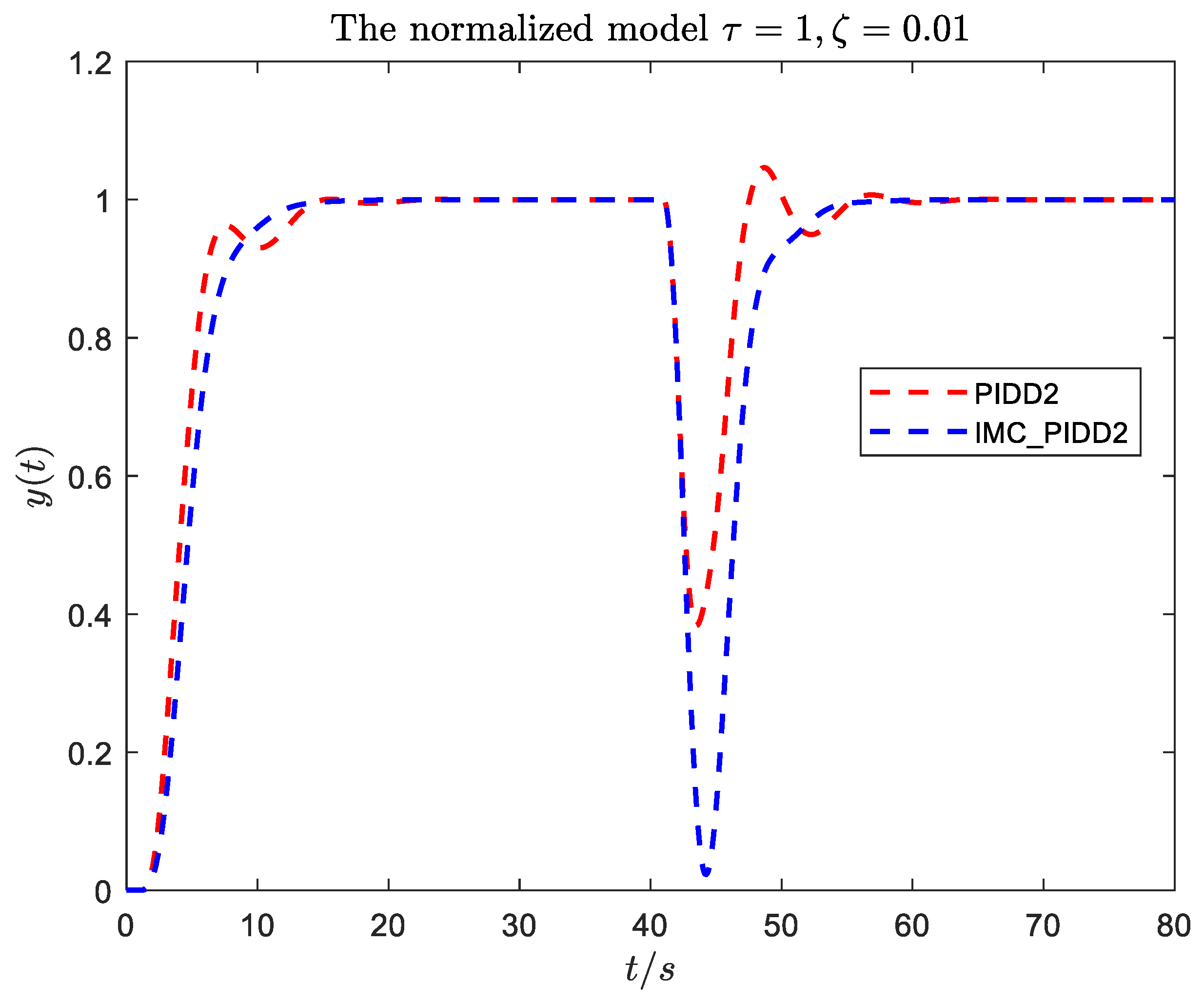
To further illustrate the necessity of the PIDD2 control method proposed in this paper, here, we use the form of simulation to carry out a simple comparative analysis with the literature [39]. The detailed specifications and step responses of the process are shown in Table 2 and Figure 2. From the Figure 2 and Table 2, key findings emerge:
(1)
The two methods are different, and the tuning formulas in [39] need to be fitted twice, and the derivation process is complicated. In this paper, a simplified method is adopted to divide the oscillating system according to the damping ratio ξ , which greatly reduces the fitting process and is more convenient for practical engineering applications. In addition, both use different controllers and have different control structures: [39] uses state space PIDD2, and this paper uses PID and PIDD2.
(2)
The disturbance rejection performance and robustness of [39] are not as good as PIDD2.
The contributions of this paper include:
  • The tuning formulas of PID/PIDD2 for the underdamped oscillatory plant are proposed.
  • The parameters of the tuning formula are obtained by minimizing the integral of time and absolute error (ITAE) under a prescribed robustness through the optimization algorithm. The simulation results verify the applicability of the proposed formulas.
The remainder of the paper contains four chapters. Section 2 describes the system models and robustness design. Section 3 presents the parameter tuning of PID controllers. Section 4 presents the parameter tuning of PIDD2 controllers. Section 5 presents an application in power system control. Finally, Section 6 presents the conclusion.

2. System Models and Robustness Design

2.1. System Models

The general industrial process control system generally includes two parts: the controller and the controlled plant. Figure 3 is the simplified structure block diagram of the system.
As is well-known, the oscillatory system can be approximated in terms of the SOPDT model; thus, we can write the corresponding equivalent form as:
P ( s ) = k T 2 s 2 + 2 T ξ s + 1 e τ s
where k , T ,   τ , and ξ are the system gain, the time constant, the time delay, and the damping ratio, respectively.
The nominal form of the controller expressions are:
C P I D ( s ) = K p + K i s + K d s
C P I D D 2 ( s ) = K p + K i s + K d s + K d d s 2
where K p ,   K i , K d , and K d d are the proportional, integral, derivative gain, and double derivative gain, respectively.

2.2. Robustness Design of Controller

To evaluate the performance of the controller, we take the integral of time and absolute error (ITAE) as the disturbance rejection capability of the closed-loop system:
I T A E = 0 t | e ( t ) | d t
where e ( t ) = r ( t ) y ( t ) is the difference between the reference input signal and the output signal of the system.
Since the system will be affected by various uncertainties in the process of operation, we need a robustness index to measure the quality of the controller design. There are two general robustness indices M s and M t , where M s and M t are maximum sensitivities,   S ( s ) and T ( s ) are sensitivity functions:
M s = m a x ω | S ( i ω ) | , S ( s ) = 1 1 + P ( s ) C ( s )
M t = m a x ω | T ( i ω ) | , T ( s ) = P ( s ) C ( s ) 1 + P ( s ) C ( s )
According to [30,40], we can obtain a measure of the robustness of single-loop control systems:
ε : = s u p ω ( | S ( i ω ) | + | T ( i ω ) | )
where ε represents the robustness of the system, and the larger ε is, the worse the robustness. To ensure that the system has appropriate robustness, we choose ε < 2.5 .

3. Parameter Tuning of PID Controllers

Here, we consider the transfer function of the normalized second-order oscillatory system model, with the normalized delay time τ ¯ = τ / T [41]:
P ( s ) = 1 s 2 + 2 ξ s + 1 e τ ¯ s
Now that we have the model for the system in model (8), how to make full use of the known parameter information of the model to obtain the controller parameters is the focus of this section. It has been mentioned above that the value of damping ξ is vital for the underdamped oscillatory system. In general, when ξ < 0.4 , it is a heavily oscillatory system; otherwise, it is a moderately oscillatory system. The basic requirements of the control system are moderate damping, fast response speed, and short settling time. The above two cases also have different demands for the controller. For simplicity, we study the problem of controller parameter tuning for the underdamped oscillatory systems under two cases: ξ = 0 and ξ = 0.4 , i.e., we use model (8) with ξ = 0 to represent the heavily oscillatory systems and derive the tuning formula for systems with ξ < 0.4 , and model (8) with ξ = 0.4   to represent moderately oscillatory systems and derive the tuning formula for systems with ξ 0.4 . It is possible to derive tuning formulas for each ξ , however, this is quite complicated, as was previously performed in [16,17] for the tuning of active disturbance rejection controllers. We note that the PID/PIDD2 controllers are robust against the damping ratio, so we can simplify the tuning procedure into two cases.
Now, we can move on to the controller parameter optimization issue. The specific process of parameter optimization is:
m i n K ¯ p , K ¯ i , K ¯ d   I T A E s .   t .   ε < 2.5
Remark 2. 
 
Step 1: Initialize the controller’s parameters  K p ,    K i , and  K d  (or  K p ,    K i ,  K d , and  K d d ).
Step 2: Parameters iteration: to minimize the load disturbance attenuation performance in the integral of time and absolute error (ITAE) sense, under the constraint of a specified robustness measure ( ε < 2.5 ) for the second-order process with a dead-time (SOPDT) process model.
Step 3: If Step 2 meets the requirements, the controller parameters can be obtained, otherwise, the iteration continues until the requirements are met.
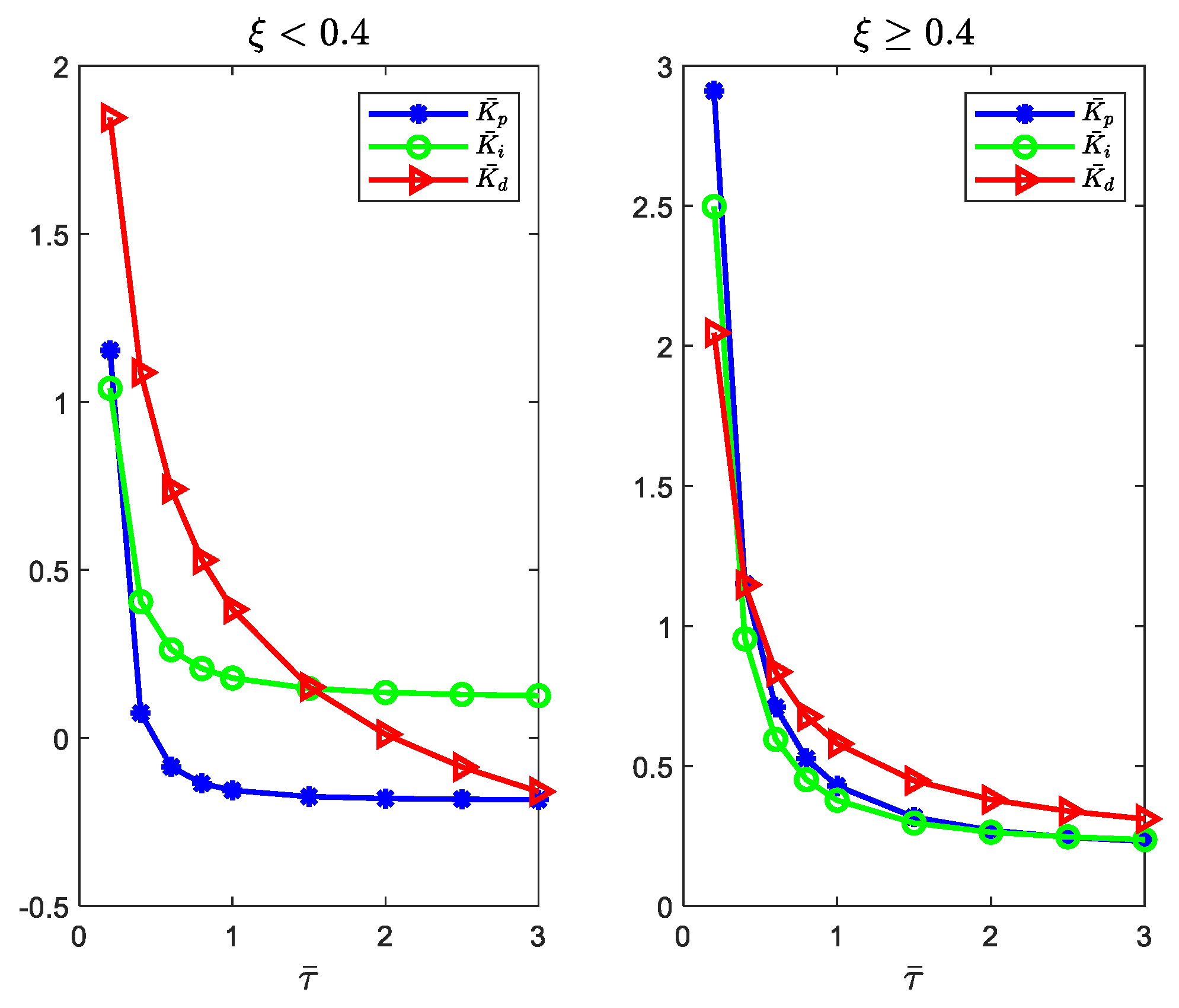
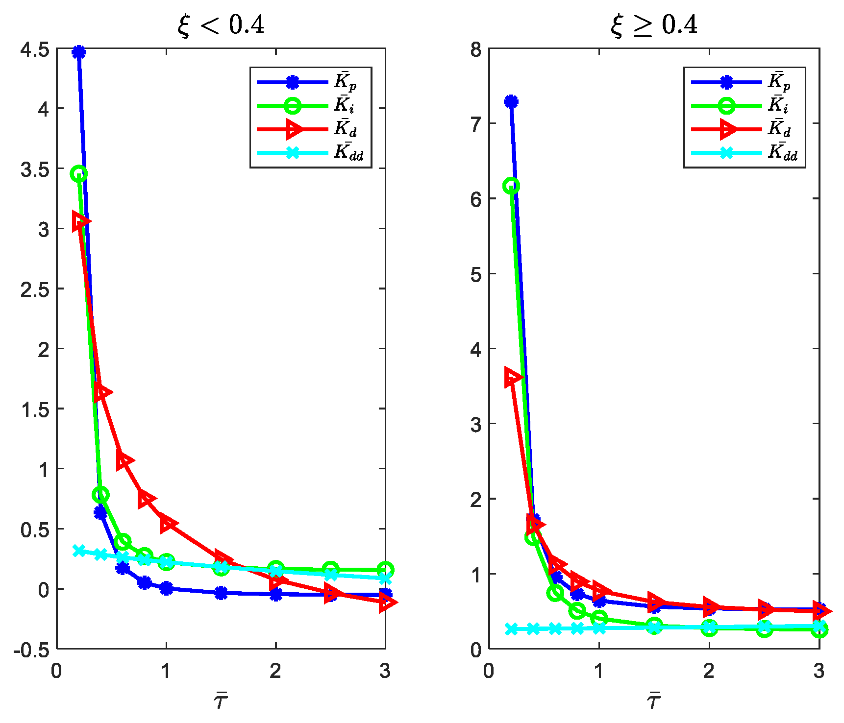
From the optimization process above, the parameters’ fitting curves for plant (8) are shown in Figure 4, and the tuning formulas are shown in (10) ( ξ < 0.4 ) and (11) ( ξ 0.4 ).
K ¯ p = 0.02987 τ ¯ 2.363 0.186   K ¯ i = 0.06231 τ ¯ 1.676 + 0.1159 K ¯ d = 1.41 τ ¯ 0.4422 1.027   ( ξ < 0.4 )
K ¯ p = 0.2455 τ ¯ 1.496 + 0.183   K ¯ i = 0.1691 τ ¯ 1.619 + 0.2083   K ¯ d = 0.4185 τ ¯ 0.9354 + 0.1609   ( ξ 0.4 )
For the general SOPDT plant (1), the tuning formula (10) can be converted into (12), and (11) can be converted into (13) [41].
K p = 1 k ( 0.02987 ( τ T ) 2.363 0.186 )   K i = 1 k T ( 0.06231 ( τ T ) 1.676 + 0.1159 ) K d = T k ( 1.41 ( τ T ) 0.4422 1.027 )   ( ξ < 0.4 )
K p = 1 k ( 0.2455 ( τ T ) 1.496 + 0.183 )   K i = 1 k T ( 0.1691 ( τ T ) 1.619 + 0.2083 ) K d = T k ( 0.4185 ( τ T ) 0.9354 + 0.1609 ) ( ξ 0.4 )
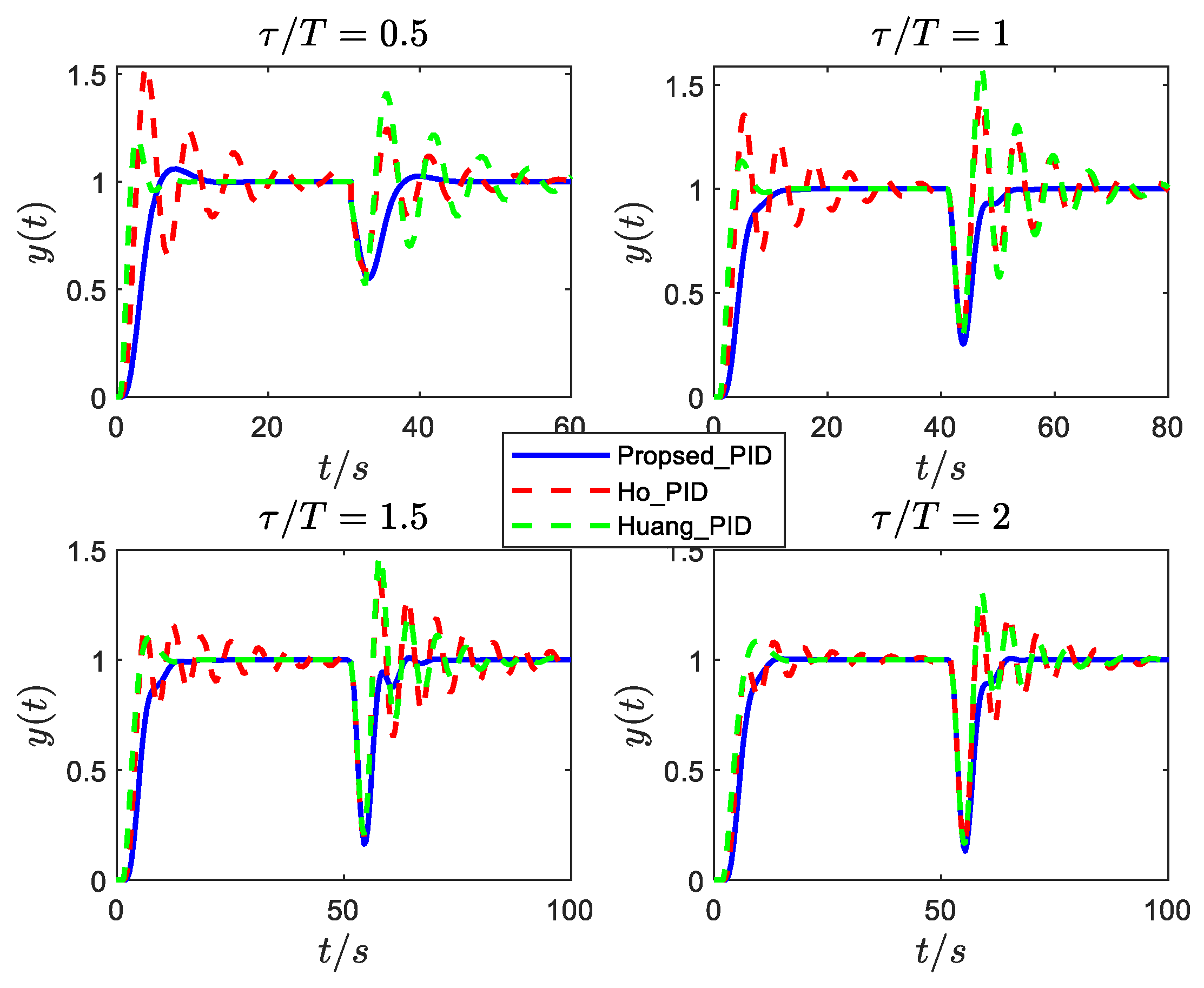
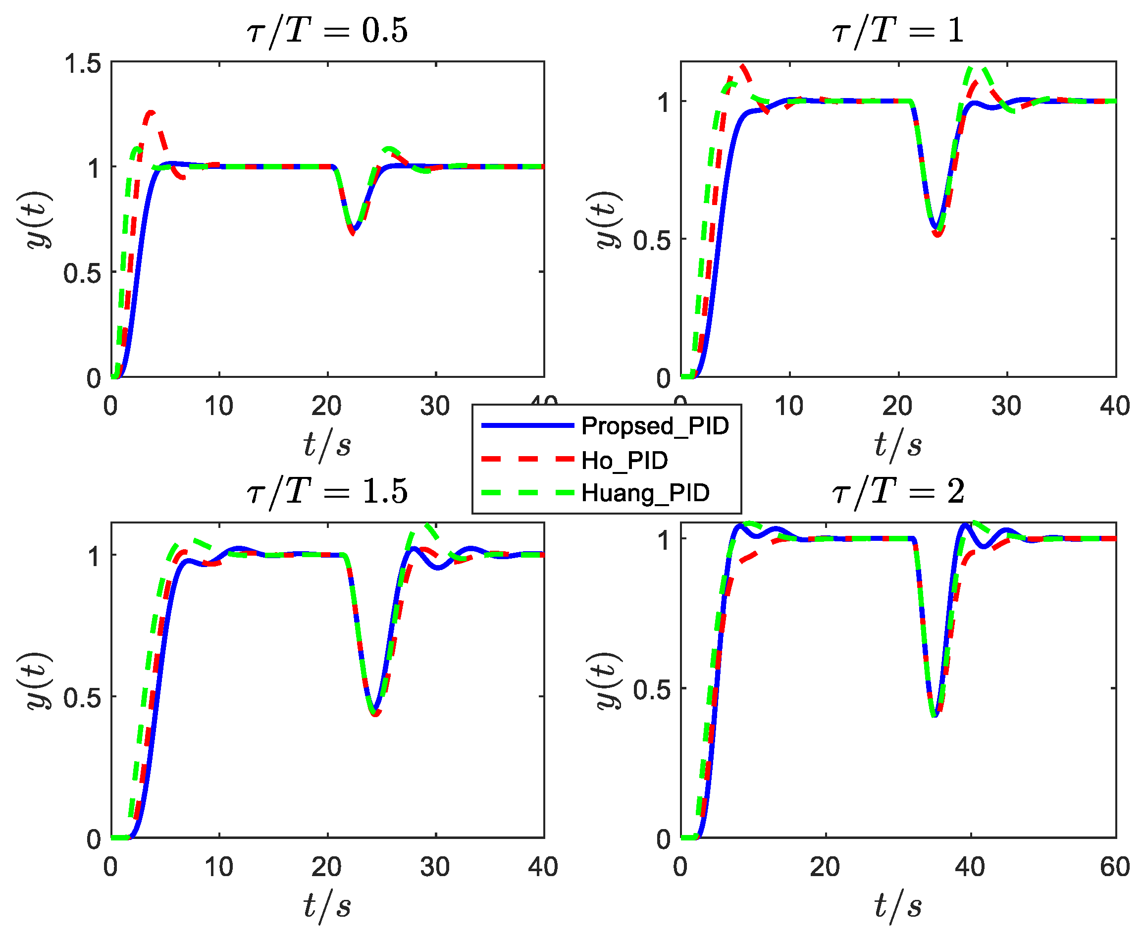
The responses of the normalized second-order oscillatory plants (8) with different damping ratios and time delays are shown in Figure 5, Figure 6 and Figure 7 (we focus on robustness and disturbance rejection performance; the tracking performance can be improved by setting a suitable weight factor to the controller’s proportional gain). The responses are for a step reference signal at t = 0   s and a step input disturbance signal is added to these systems at an appropriate time to test the disturbance rejection performance and robustness. As we can observe, for systems with small damping ( ξ < 0.4 ), the proposed tuning formula (12) is slightly slow in disturbance rejection, but has a very small oscillation, while the responses of the other two methods are quite oscillatory. For systems with large damping ( ξ 0.4 ), the proposed tuning formula (13) has a better control effect than the other two methods.
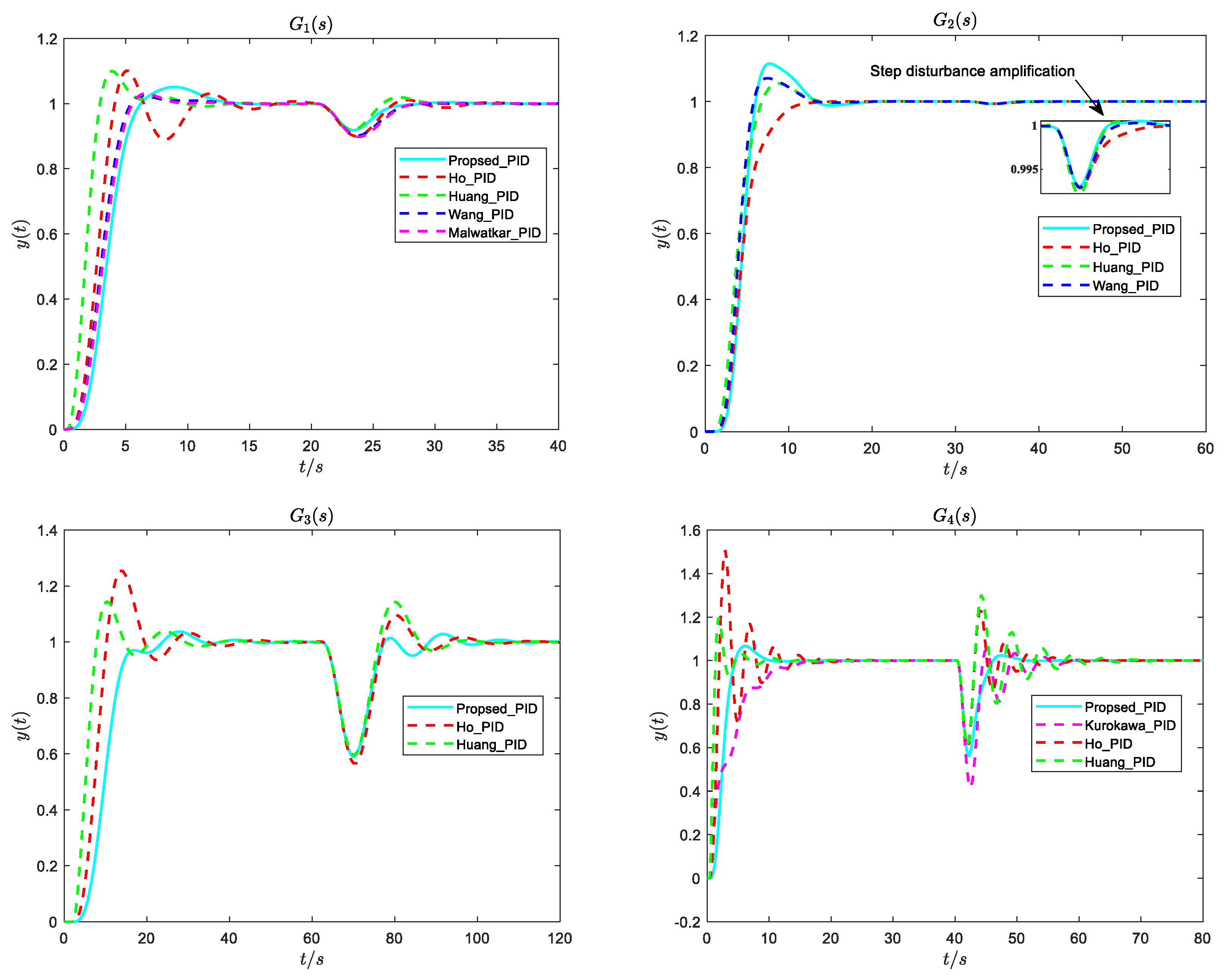
Consider the following oscillatory examples for ( G 1 ( s ) G 2 ( s ) [20], G 3 ( s ) [27], G 4 ( s ) [29]):
  G 1 ( s ) = 1 ( s 2 + s + 1 ) ( s + 2 ) 2 e 0.1 s , G 2 ( s ) = 1 ( s 2 + 2 s + 3 ) 3 ( s + 3 ) e 0.3 s G 3 ( s ) = 1 ( 9 s 2 + 2.4 s + 1 ) ( s + 1 ) e 2 s , G 4 ( s ) = 1.5210 s 2 + 0.3380 s + 1.6900 e 0.37 s
Dynamic responses of the plants are given in Figure 8. The controller parameters, system parameters., and controller performance indexes are shown in Table 3. From Figure 8 and Table 3, we can see that the proposed PID controller exhibits a satisfactory control performance, especially when the ξ < 0.4 (such as G 4 ( s ) ). The tracking overshoot of G 2 ( s ) can be reduced by setting the weight of the response to the controller’s proportional gain. It is worth noting that the control effect is good when enlarging the disturbance response of G 2 ( s ) . Both G 1 ( s ) and G 3 ( s ) can also achieve good control effect. Overall, the PID tuning methods proposed in this paper trade-off between disturbance rejection performance and robustness.
.

4. Parameter Tuning of PIDD2 Controllers

PIDD2, as a variant of PID, has a new degree of freedom (differential action) in comparison to PID, which can accelerate the transient and closed-loop performance of the control system [42], and contributes to promoting the phase margin, steady-state accuracy and stability of the controlled plant [43]. As such, in this section, we adopt the PIDD2 controller for the control of the underdamped oscillatory systems with time delays.
Similar to the parameter optimization process in Section 3, we can obtain the PIDD2 controller parameters and the fitting curves for normalized plant (8) as shown in Figure 9, the tuning formulas for (8) as (15) and (16).
K ¯ p = 0.05731 τ ¯ 2.714 0.05446 K ¯ i = 0.071 τ ¯ 2.386 + 0.1508   K ¯ d = 1.246 τ ¯ 0.6861 0.6993   K ¯ d d = 0.1609 τ ¯ 0.5542 + 0.3826   ( ξ < 0.4 )
K ¯ p = 0.1237 τ ¯ 2.487 + 0.5163   K ¯ i = 0.1587 τ ¯ 2.249 + 0.2437   K ¯ d = 0.3494 τ ¯ 1.375 + 0.4229   K ¯ d d = 0.01554 τ ¯ 0.9568 + 0.2602   ( ξ 0.4 )
The tuning formulas (15) and (16) for normalized plant (8) can be converted to the general form of (17) and (18) for general SOPDT plant (1) [41]:
K p = 1 k ( 0.05731 ( τ T ) 2.714 0.05446 ) K i = 1 k T ( 0.071 ( τ T ) 2.386 + 0.1508 )   K d = T k ( 1.246 ( τ T ) 0.6861 0.6993 )   K d d = T 2 k ( 0.1609 ( τ T ) 0.5542 + 0.3826 ) ( ξ < 0.4 )
K p = 1 k ( 0.1237 ( τ T ) 2.487 + 0.5163 )   K i = 1 k T ( 0.1587 ( τ T ) 2.249 + 0.2437 )   K d = T k ( 0.3494 ( τ T ) 1.375 + 0.4229 )   K d d = T 2 k ( 0.01554 ( τ T ) 0.9568 + 0.2602 ) ( ξ 0.4 )
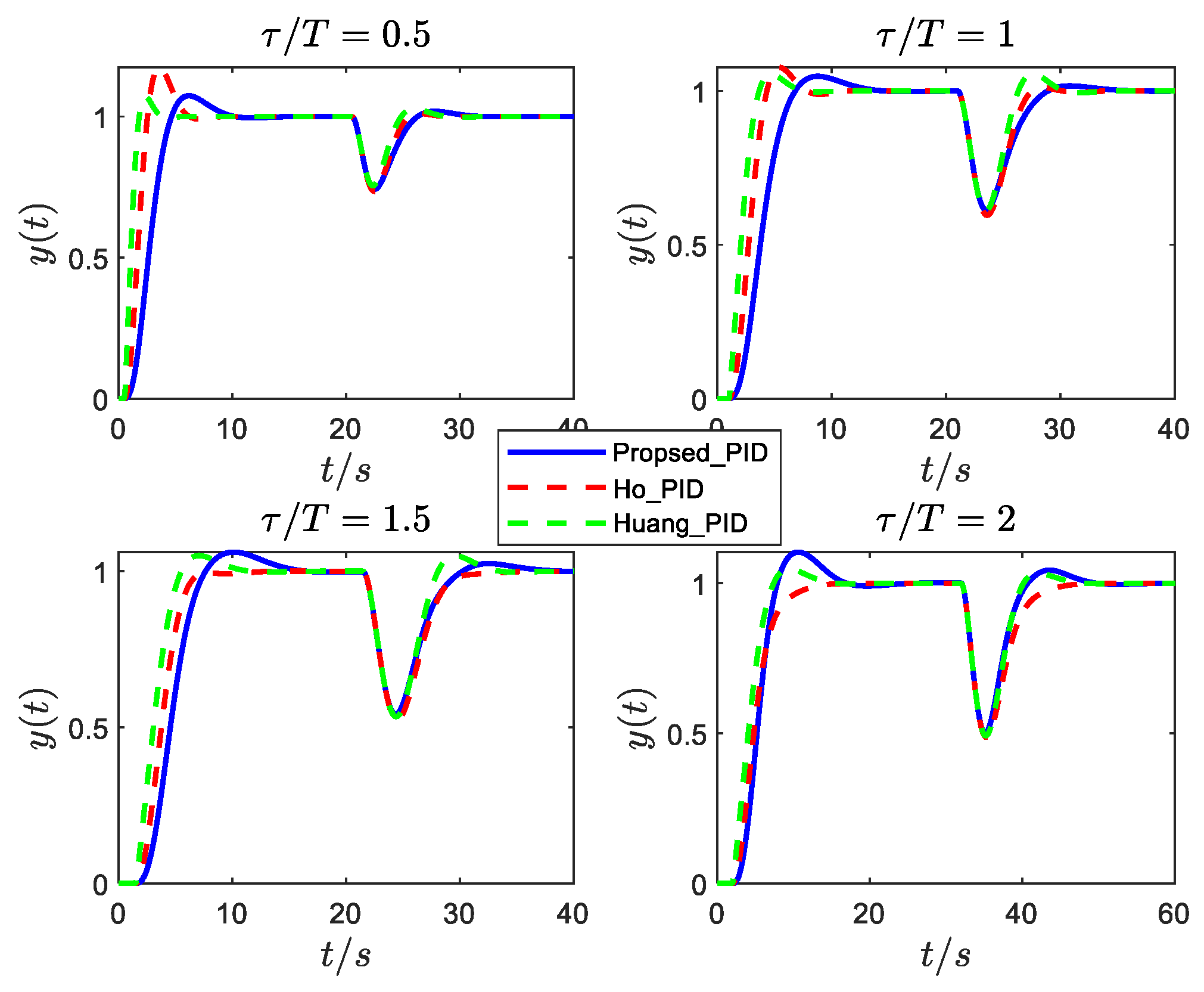
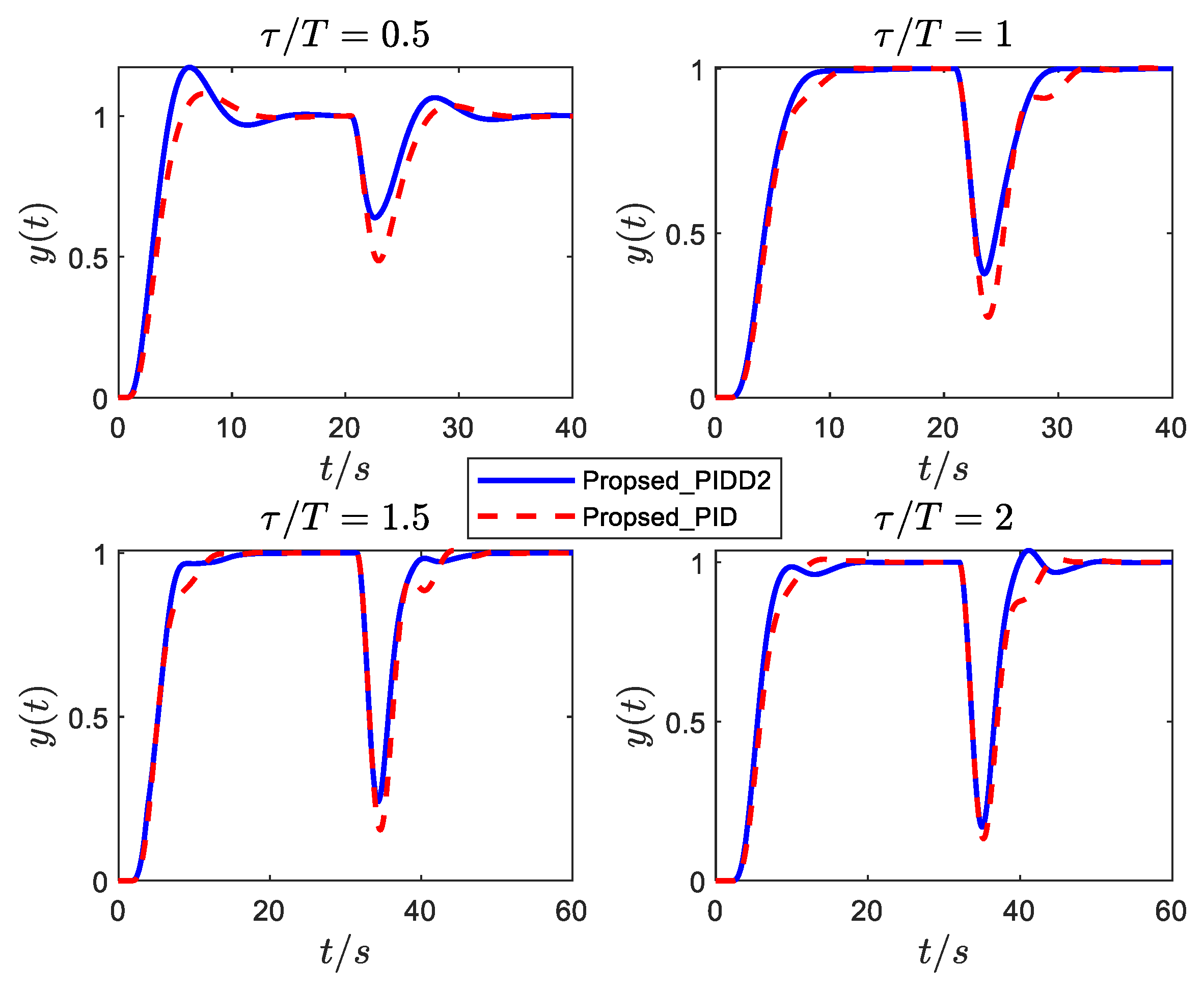
Figure 10, Figure 11 and Figure 12 show the responses of the normalized SOPDT system (8) under different damping ξ = 0.1 ,   0.4 ,   0.6 with a step reference signal at t = 0   s and a step input disturbance signal is added to these systems at an appropriate time. It can be observed from the simulation results that:
(1)
The control performance (especially disturbance rejection performance) of the proposed PIDD2 is improved compared with that of PID.
(2)
The control performance of PIDD2 has no significant advantage over the proposed PID as the τ / T increases. Therefore, PIDD2 can improve the performance of PID for SOPDT systems with small delay; however, for large delay, the control improvement of PIDD2 is not noticeable.
Since PIDD2 controller can improve the performance of PID controller under certain conditions (as explained in the previous subsection), to verify the applicability of PIDD2, we conduct a simulation and a comparative analysis with the step responses of several typical complex oscillatory plants (( G 5 ( s ) , G 6 ( s ) , G 8 ( s ) [21], G 7 ( s ) [28])).
  G 5 ( s ) = 15 ( s 2 + 0.9 s + 5 ) ( s + 3 ) , G 6 ( s ) = 18 ( s 2 + s + 2 ) ( s + 3 ) 2 G 7 ( s ) = 15.4358 ( s 2 + 3.79436 s + 68.695 ) e 0.4 s , G 8 ( s ) = 20 ( s 2 + 2.4 s + 4 ) ( s + 5 ) e 2 s
Dynamic responses of plants and parameters of the PIDD2 and PID are given in Figure 13 and Table 4. From G 5 and G 6 , it can be seen that the control effect of PIDD2 is better than that of PID, both in terms of tracking speed and disturbance attenuation performance, which is further illustrated by combining the two indexes of settling time and overshoot in Table 4. While G 7 and G 8 are not obviously seen in Figure 13, a numerical analysis and comparison can also result in the same conclusion from Table 4. Based on the results, the main conclusion that can be drawn is that the tuning formula of the PIDD2 controller proposed in this paper can indeed improve the performance of the tuning formula of the PID controller.

5. Application in Power System Control

One of the most important roles in power system operation is to maintain a continuous energy power supply to the consumers while considering quality and security requirements. This objective is achieved by matching the total generation with the total load by using the well-known load frequency control (LFC). It is widely acknowledged that LFC systems are typical oscillatory SOPDT systems [12], which is a very important factor in the operation of power systems and provide fast load disturbance rejection and robust performance in the presence of uncertainties. However, research on frequency stability (balance between power supply and generation) faces serious challenges that constrain the development of power systems. Renewable energy has become a popular research topic in recent years. It is encouraging that the participation of renewable energy sources such as electric vehicles can effectively improve the frequency stability of the power system [44,45]. Therefore, the proposed controller is applied to the LFC system with electric vehicles in this section to test its feasibility.
To illustrate the issue, we take the benchmark system with electric vehicles as an example [46]. The transfer function model of the LFC system is shown in Figure 14. The specific parameter values of the transfer function are: M = 0.1667 ,   D = 0.0083 ,   R = 2.4 ,   T g = 0.08 ,   T t = 0.3 ,   K r = 0.5 ,   T r = 10 ,   T e = 1 ,   a g = 0.9 ,   a e = 0.1 . The transfer function of each part is below.
Governor : G g ( s ) = 1 T g s + 1 Turbine : G t ( s ) = 1 T t s + 1 Reheat   turbine : G r ( s ) = K r T r T r s + 1 Generator : G p ( s ) = 1 M s + D Electric   vehicles : G e ( s ) = 1 T e s + 1
The load frequency control system can be approximated as the SOPDT model [12]. Thus, the approximated SOPDT model parameters are K = 2.3547 , T = 0.6461 , ξ = 0.5285 , τ = 0.0646 . The controller parameters can be obtained according to (13) and (18).
A step disturbance signal of Δ P d = 0.01 p u is added at t = 5   s . The dynamic response of the frequency deviation is shown in Figure 15. From Figure 15, we can conclude that the proposed tuning formula has a faster response speed and better disturbance rejection performance. Nevertheless, the proposed tuning formulas have more advantages (disturbance rejection capability) in the load frequency control system.

6. Conclusions

The main goal of the current study was to put forward the tuning formula for PID/PIDD2 controllers for second-order oscillatory systems with time delays. The tuning formulas are obtained by the optimization algorithm to minimize the ITAE under a robustness constraint. The proposed formulas are used on a variety of plants; it should be noted that the PIDD2 controller can improve the performance of the PID under a small time delay, but for large time delay, its effect is not obvious. In contrast to the other PID tuning formulas, the advantage of our study is that the proposed PID/PIDD2 tuning method can provide good robustness and disturbance rejection performance.
The present study confirmed the findings about a new understanding of PID controllers. A further study should consider filter tuning for PID/PIDD2 controllers and PID/PIDD2 control for higher-order oscillatory systems with zeros.

Author Contributions

Conceptualization, X.H.; methodology, X.H.; software, X.H.; validation, X.H.; formal analysis, X.H.; investigation, X.H.; writing—original draft preparation, X.H.; writing—review and editing, X.H. and W.T.; supervision, W.T. and G.H.; project administration, G.H. All authors have read and agreed to the published version of the manuscript.

Funding

This research received no external funding.

Data Availability Statement

Data are presented in the article.

Conflicts of Interest

The authors declare no conflict of interest.

References

  1. Albatran, S.; Smadi, I.A.; Bataineh, H.A. Generalized Optimal and Explicit PI/PID Tuning Formulas for Underdamped Second-order Systems. Int. J. Control Autom. Syst. 2020, 18, 1023–1032. [Google Scholar] [CrossRef]
  2. Kim, M.; Lee, S.-U. PID with a Switching Action Controller for Nonlinear Systems of Second-order Controller Canonical Form. Int. J. Control Autom. Syst. 2021, 19, 2343–2356. [Google Scholar] [CrossRef]
  3. Zhang, M.-L.; Zhang, Y.-J.; He, X.-L.; Gao, Z.-J. Adaptive PID Control and Its Application Based on a Double-Layer BP Neural Network. Processes 2021, 9, 1475. [Google Scholar] [CrossRef]
  4. Chao, C.-T.; Sutarna, N.; Chiou, J.-S.; Wang, C.-J. An optimal fuzzy PID controller design based on conventional PID control and nonlinear factors. Appl. Sci. 2019, 9, 1224. [Google Scholar] [CrossRef] [Green Version]
  5. Halikias, G.D.; Zolotas, A.C. Optimal design of PID controllers using the QFT method. IEE Proc. Control Theory Appl. 1999, 146, 585–589. [Google Scholar]
  6. Chevalier, A.; Francis, C.; Copot, C.; Ionescu, C.M.; De Keyser, R. Fractional-order PID design: Towards transition from state-of-art to state-of-use. ISA Trans. 2019, 84, 178–186. [Google Scholar] [CrossRef]
  7. Gundes, A.N.; Ozguler, A.B. PID Stabilization of MIMO Plants. IEEE Trans. Autom. Control 2007, 52, 1502–1508. [Google Scholar] [CrossRef]
  8. Huey, J.R.; Sorensen, K.L.; Singhose, W.E. Useful applications of closed-loop signal shaping controllers. Control Eng. Pract. 2008, 16, 836–846. [Google Scholar] [CrossRef]
  9. Ghorai, P.; Majhi, S.; Kasi, V.R.; Pandey, S. Parameter Identification of Delayed Under-Damped Systems Using On-Line Relay Autotuning. IEEE Trans. Circuits Syst. II Express Briefs 2019, 66, 1197–1201. [Google Scholar] [CrossRef]
  10. Ghorai, P.; Majhi, S.; Pandey, S. Closed-loop Relay Experiment for Modeling of Underdamped Plant Dynamics. In Proceedings of the 2019 Fifth Indian Control Conference (ICC), New Delhi, India, 9–11 January 2019; pp. 424–429. [Google Scholar]
  11. Singhose, W.; Seering, W. Control of flexible manipulators with input shaping techniques. In Flexible Robot Manipulators: Modelling, Simulation and Control; The Institution of Engineering and Technology: Stevenage, UK, 2008. [Google Scholar]
  12. Tan, W. Tuning of PID load frequency controller for power systems. Energy Convers. Manag. 2009, 50, 1465–1472. [Google Scholar] [CrossRef]
  13. Fu, C.; Tan, W. Decentralised load frequency control for power systems with communication delays via active disturbance rejection. IET Gener. Transm. Distrib. 2018, 12, 1397–1403. [Google Scholar] [CrossRef]
  14. Singer, N.C.; Seering, W.P. Preshaping command inputs to reduce system vibration. J. Dyn. Syst. Meas. Control 1990, 112, 76–82. [Google Scholar] [CrossRef]
  15. Singhose, W. Command shaping for flexible systems: A review of the first 50 years. Int. J. Precis. Eng. Manuf. 2009, 10, 153–168. [Google Scholar] [CrossRef]
  16. Wang, Y.; Tan, W.; Cui, W. Tuning of linear active disturbance rejection controllers for second-order underdamped systems with time delay. ISA Trans. 2021, 118, 83–93. [Google Scholar] [CrossRef] [PubMed]
  17. Wang, Y.; Tan, W.; Cui, W.; Han, W.; Guo, Q. Linear active disturbance rejection control for oscillatory systems with large time-delays. J. Frankl. Inst. 2021, 358, 6240–6260. [Google Scholar] [CrossRef]
  18. Vrančić, D.; Oliveira, P.M. Design of feedback control for underdamped systems. IFAC Proc. Vol. 2012, 45, 98–103. [Google Scholar] [CrossRef]
  19. Ho, W.K.; Hang, C.C.; Zhou, J. Self-tuning PID control of a plant with under-damped response with specifications on gain and phase margins. IEEE Trans. Control Syst. Technol. 1997, 5, 446–452. [Google Scholar]
  20. Wang, Q.-G.; Lee, T.-H.; Fung, H.-W.; Bi, Q.; Zhang, Y. PID tuning for improved performance. IEEE Trans. Control Syst. Technol. 1999, 7, 457–465. [Google Scholar] [CrossRef]
  21. Shen, J.-C. Fuzzy neural networks for tuning PID controller for plants with underdamped responses. IEEE Trans. Fuzzy Syst. 2001, 9, 333–342. [Google Scholar] [CrossRef]
  22. Skogestad, S. Simple analytic rules for model reduction and PID controller tuning. J. Process Control 2003, 13, 291–309. [Google Scholar] [CrossRef] [Green Version]
  23. Huang, H.-P.; Lee, M.-W.; Chen, C.-L. Inverse-based design for a modified PID controller. J. Chin. Inst. Chem. Eng. 2000, 31, 225–236. [Google Scholar]
  24. Lee, Y.; Park, S.; Lee, M.; Brosilow, C. PID controller tuning for desired closed-loop responses for SI/SO systems. AIChE J. 1998, 44, 106–115. [Google Scholar] [CrossRef]
  25. Chen, D.; Seborg, D.E. PI/PID Controller Design Based on Direct Synthesis and Disturbance Rejection. Ind. Eng. Chem. Res. 2002, 41, 4807–4822. [Google Scholar] [CrossRef]
  26. Ho, S.-J.; Shu, L.-S.; Ho, S.-Y. Optimizing fuzzy neural networks for tuning PID controllers using an orthogonal simulated annealing algorithm OSA. IEEE Trans. Fuzzy Syst. 2006, 14, 421–434. [Google Scholar] [CrossRef]
  27. Malwatkar, G.M.; Sonawane, S.H.; Waghmare, L.M. Tuning PID controllers for higher-order oscillatory systems with improved performance. ISA Trans. 2009, 48, 347–353. [Google Scholar] [CrossRef]
  28. Eris, O.; Kurtulan, S. A direct digital PID tuning rule for SOPDT systems. In Proceedings of the 2012 2nd Australian Control Conference, Sydney, NSW, Australia, 15–16 November 2012; pp. 66–69. [Google Scholar]
  29. Kurokawa, R.; Sato, T.; Vilanova, R.; Konishi, Y. Design of optimal PID control with a sensitivity function for resonance phenomenon-involved second-order plus dead-time system. J. Frankl. Inst. 2020, 357, 4187–4211. [Google Scholar] [CrossRef]
  30. Panda, R.C.; Yu, C.-C.; Huang, H.-P. PID tuning rules for SOPDT systems: Review and some new results. ISA Trans. 2004, 43, 283–295. [Google Scholar] [CrossRef]
  31. McFarlane, D.C.; Glover, K. Robust Controller Design Using Normalized Coprime Factor Plant Descriptions; Springer: Berlin/Heidelberg, Germany, 1990. [Google Scholar]
  32. Koley, I.; Sarkar, B.; Datta, A.; Panda, G.K. Load Frequency Control of a Wind Energy Integrated Multiarea Power System With CSA Tuned PIDD Controller. In Proceedings of the 2020 IEEE First International Conference on Smart Technologies for Power, Energy and Control (STPEC), Nagpur, India, 25–26 September 2020; pp. 1–6. [Google Scholar]
  33. Izvoreanu, B.; Cojuhari, I. The Tuning of the PID and PIDD2 Algorithms to the Model Objects with Inertia and Identical Elements and Time Delay. 2013. Available online: http://repository.utm.md/handle/5014/17375 (accessed on 12 June 2023).
  34. Sonkar, P.; Rahi, O.P. Unified tuning of PID-derivative filter load frequency controller for two area interconnected system including wind power plant. In Proceedings of the 2016 IEEE Uttar Pradesh Section International Conference on Electrical, Computer and Electronics Engineering (UPCON), Varanasi, India, 9–11 December 2016; pp. 388–393. [Google Scholar]
  35. Chatterjee, S.; Dalel, M.A.; Palavalasa, M. Design of PID plus second order derivative controller for automatic voltage regulator using whale optimizatio algorithm. In Proceedings of the 2019 3rd International Conference on Recent Developments in Control, Automation & Power Engineering (RDCAPE), Noida, India, 10–11 October 2019; pp. 574–579. [Google Scholar]
  36. Mohanty, B. Performance analysis of moth flame optimization algorithm for AGC system. Int. J. Model. Simul. 2019, 39, 73–87. [Google Scholar] [CrossRef]
  37. Mohanty, B. Hybrid flower pollination and pattern search algorithm optimized sliding mode controller for deregulated AGC system. J. Ambient Intell. Humaniz. Comput. 2020, 11, 763–776. [Google Scholar] [CrossRef]
  38. Kalyan, C.N.s. UPFC and SMES based Coordinated Control Strategy for Simultaneous Frequency and Voltage Stability of an Interconnected Power System. In Proceedings of the 2021 1st International Conference on Power Electronics and Energy (ICPEE), Bhubaneswar, India, 2–3 January 2021; pp. 1–6. [Google Scholar]
  39. Hu, X.; Hou, G.; Tan, W. Tuning of PIDD2 controllers for oscillatory systems with time delays. Front. Control Eng. 2023, 3, 32. [Google Scholar]
  40. Segovia, V.R.; Hagglund, T.; Astrom, K.J. Noise filtering in PI and PID Control. In Proceedings of the 2013 American Control Conference, Washington, DC, USA, 17–19 June 2013; pp. 1763–1770. [Google Scholar]
  41. Zhang, B.; Tan, W.; Li, J. Tuning of linear active disturbance rejection controller with robustness specification. ISA Trans. 2019, 85, 237–246. [Google Scholar] [CrossRef]
  42. Veinović, S.; Stojić, D.; Ivanović, L. Optimized PIDD2 controller for AVR systems regarding robustness. Int. J. Electr. Power Energy Syst. 2023, 145, 108646. [Google Scholar] [CrossRef]
  43. Kumar, M.; Hote, Y.V. PIDD2 Controller Design Based on Internal Model Control Approach for a Non-Ideal DC-DC Boost Converter. In Proceedings of the 2021 IEEE Texas Power and Energy Conference (TPEC), College Station, TX, USA, 2–5 February 2021; pp. 1–6. [Google Scholar]
  44. Jayasinghe, S.G.; Vilathgamuwa, D.M.; Madawala, U.K. Direct integration of battery energy storage systems in distributed power generation. IEEE Trans. Energy Convers. 2011, 26, 677–685. [Google Scholar] [CrossRef]
  45. de Souza Ribeiro, L.A.; Saavedra, O.R.; De Lima, S.L.; de Matos, J. Isolated micro-grids with renewable hybrid generation: The case of Lençóis island. IEEE Trans. Sustain. Energy 2010, 2, 1–11. [Google Scholar] [CrossRef]
  46. Pham, T.N.; Trinh, H.; Van Hien, L. Load frequency control of power systems with electric vehicles and diverse transmission links using distributed functional observers. IEEE Trans. Smart Grid 2015, 7, 238–252. [Google Scholar] [CrossRef]
Figure 1. Comparison of existing PID tuning methods for the underdamped SOPDT systems. (a) Robustness measure ε . (b) Disturbance rejection performance (ITAE). (c) The step response of the process (the normalized model τ = 1, ξ = 0.2).
Electronics 12 03168 g001aElectronics 12 03168 g001b
Figure 2. Comparison of existing PIDD2 tuning methods for the underdamped SOPDT systems.
Electronics 12 03168 g002
Figure 3. The simplified structure of the control system.
Electronics 12 03168 g003
Figure 4. The parameters and the fitting curves of the PID controller.
Electronics 12 03168 g004
Figure 5. Responses of ξ = 0.1 under different PID controllers.
Electronics 12 03168 g005
Figure 6. Responses of ξ = 0.4 under different PID controllers.
Electronics 12 03168 g006
Figure 7. Responses of ξ = 0.6 under different PID controllers.
Electronics 12 03168 g007
Figure 8. Responses of G 1 ( s ) , G 2 ( s ) ,   G 3 ( s ) ,   G 4 ( s ) .
Electronics 12 03168 g008
Figure 9. The parameters and the fitting curves of the PIDD2 controller.
Electronics 12 03168 g009
Figure 10. Responses of ξ = 0.1 under PID and PIDD2 controllers.
Electronics 12 03168 g010
Figure 11. Responses of ξ = 0.4 under PID and PIDD2 controllers.
Electronics 12 03168 g011
Figure 12. Responses of ξ = 0.6 under PID and PIDD2 controllers.
Electronics 12 03168 g012
Figure 13. Responses of the proposed PIDD2 and PID.
Electronics 12 03168 g013
Figure 14. The transfer function model of the load frequency control system.
Electronics 12 03168 g014
Figure 15. Frequency deviation of power system.
Electronics 12 03168 g015
Table 1. Performance indices of existing PID tuning methods for the underdamped SOPDT systems.
τ ξ = 0.1 0.20.30.40.50.6
0.8Ho [19] ε = 2.67422.29712.19002.13872.10992.0913
ITAE = 167.8861147.0132134.4632126.8786122.2789119.6878
Maclaurin [30] ε = 10.274920.49348.21386.49835.45164.9848
ITAE = 181.0100152.0334134.7830123.8297116.3050111.0823
Chen [25] ε = 15.205721.03517.82105.26784.22243.6717
ITAE = 163.0601142.4455128.8943120.5432115.5798112.6540
Huang [23] ε = 3.27822.84442.68592.60202.55502.5224
ITAE = 176.2622153.3725139.1954130.1162123.8912119.4415
1.2Ho [19] ε = 2.16392.03462.00472.00902.01562.0187
ITAE = 170.7906151.0417140.0866134.2907131.5404130.7761
Maclaurin [30] ε = 4.323733.612111.50896.55985.45004.7244
ITAE = 219.7949189.0479165.3703148.7675137.2231129.2231
Chen [25] ε = 1.94433.64293.03892.37842.05171.9003
ITAE = 152.5156143.8841140.3592138.5792137.1669135.8013
Huang [23] ε = 2.99662.68852.57662.51832.48562.4641
ITAE = 171.4444154.4553144.0193137.7687133.8287131.1532
1.6Ho [19] ε = 1.98201.98611.99131.99622.00052.0042
ITAE = 169.3500151.5267142.8030139.5709139.8092140.5478
Maclaurin [30] ε = 3.418713.966310.08286.18664.87604.2371
ITAE = 220.5395193.8723172.8015157.2165146.3086138.7042
Chen [25] ε = 2.58082.20932.11802.06341.96391.9684
ITAE = 160.6442158.0982156.4578154.9632153.5713152.2662
Huang [23] ε = 2.84412.60612.51992.47602.45192.4356
ITAE = 167.8376152.6414144.7046141.1966139.7917138.8289
2.0Ho [19] ε = 1.99481.99641.99822.00012.00192.0036
ITAE = 167.7916152.2218147.2653147.2348147.8758148.5063
Maclaurin [30] ε = 5.606917.38696.78064.83914.06913.6961
ITAE = 210.8966188.2239170.9862158.5524149.8659143.8656
Chen [25] ε = 2.71572.55612.43012.33222.25742.2047
ITAE = 171.0477169.3779167.9577166.6392165.3989164.2274
Huang [23] ε = 2.75122.55632.48912.45482.43402.4202
ITAE = 165.9403151.9473146.8995145.7931145.4290145.2653
Table 2. Parameters of the PIDD2 and IMC_PIDD2 controllers.
MethodsController ParametersDisturbance RejectionRobustness IndexITAE Index
K p K i K d K d d T s / s σ % ε
PIDD20.00280.22180.54670.221710.5602.51061.063 × 10³
IMC_PIDD2−0.39540.12380.2618−0.018714.7973.11202.103 × 10³
Table 3. Parameters of the PID controllers.
System ParametersMethodsController ParametersDisturbance
Rejection
Robustness
Index
ITAE Index
ξ τ T K p K i K d T s / s σ % ε
G10.49110.83701.1207Proposed_PID2.53141.92433.58218.58947.12.1349121.0161
Malwatkar_PID [27]1.30391.31041.33518.32810.181.8672164.6253
Wang_PID [20]1.5031.3661.71510.2878.961.7707155.7447
Huang_PID [23]2.95702.68643.37408.7248.072.4594116.8912
Ho_PID [19]2.1471.4840.77714.7569.962.7118193.5172
G20.49271.85400.7927Proposed_PID20.736426.071222.83814.702.447113.1827
Wang_PID [20]17.56222.48514.134.8602.379613.1787
Huang_PID [23]17.34222.20313.9534.8802.395613.5873
Ho_PID [19]13.71217.05110.7154.8202.012416.3049
G30.41542.33.2024Proposed_PID0.58580.15532.341843.7403.05693.86 × 103
Huang_PID [23]0.57840.21742.229447.1925363.06575.32 × 103
Ho_PID [19]0.49500.16691.712144.8243.52.49285.14 × 103
G40.130.370.7692Proposed_PID−0.01960.47430.787910.087844.82.1503393.2047
Kurokawa_PID [29]0.09320.29030.231117.683358.22.1007939.5594
Huang_PID [23]0.30031.50150.888524.627539.12.96451.326 × 103
Ho_PID [19]0.35651.15310.682319.011239.22.5466844.5659
Table 4. Parameters of the PIDD2 and PID controllers for (19).
System ParametersMethodsController ParametersDisturbance
Rejection
Robustness
Index
ITAE
Index
ξ τ T K p K i K d K d d T s / s σ % ε
G50.19990.20.4468PIDD2
PID
0.4533
0.0136
1.4191
0.7958
0.6539
0.44
0.05583.11
6.72
23.8
40
1.7173
1.7548
102.1007
181.4656
G60.36500.480.8111PIDD2
PID
0.1835
−0.083
0.4920
0.3380
0.8813
0.6093
0.172612.482
15.721
33.4
42.9
1.6918
1.9740
575.9491
888.3398
G70.22890.40.1207PIDD2
PID
−0.232
−0.812
5.7124
4.5834
−0.081
−0.106
0.00453.5782
4.0958
16
16
3.5385
3.5748
16.3339
21.6371
G80.62.20.4775PIDD2
PID
0.5191
0.2080
0.5211
0.4661
0.2224
0.1247
0.074632.006
36.163
53.9
53.9
5.5247
5.9557
2.36 × 10³
3.96 × 10³
Disclaimer/Publisher’s Note: The statements, opinions and data contained in all publications are solely those of the individual author(s) and contributor(s) and not of MDPI and/or the editor(s). MDPI and/or the editor(s) disclaim responsibility for any injury to people or property resulting from any ideas, methods, instructions or products referred to in the content.