


Wireless Device with Energy Management for Closed-Loop Deep Brain Stimulation (CLDBS)

 , ,
, ,  ,
,  ,
,  and
and 
Abstract
1. Introduction
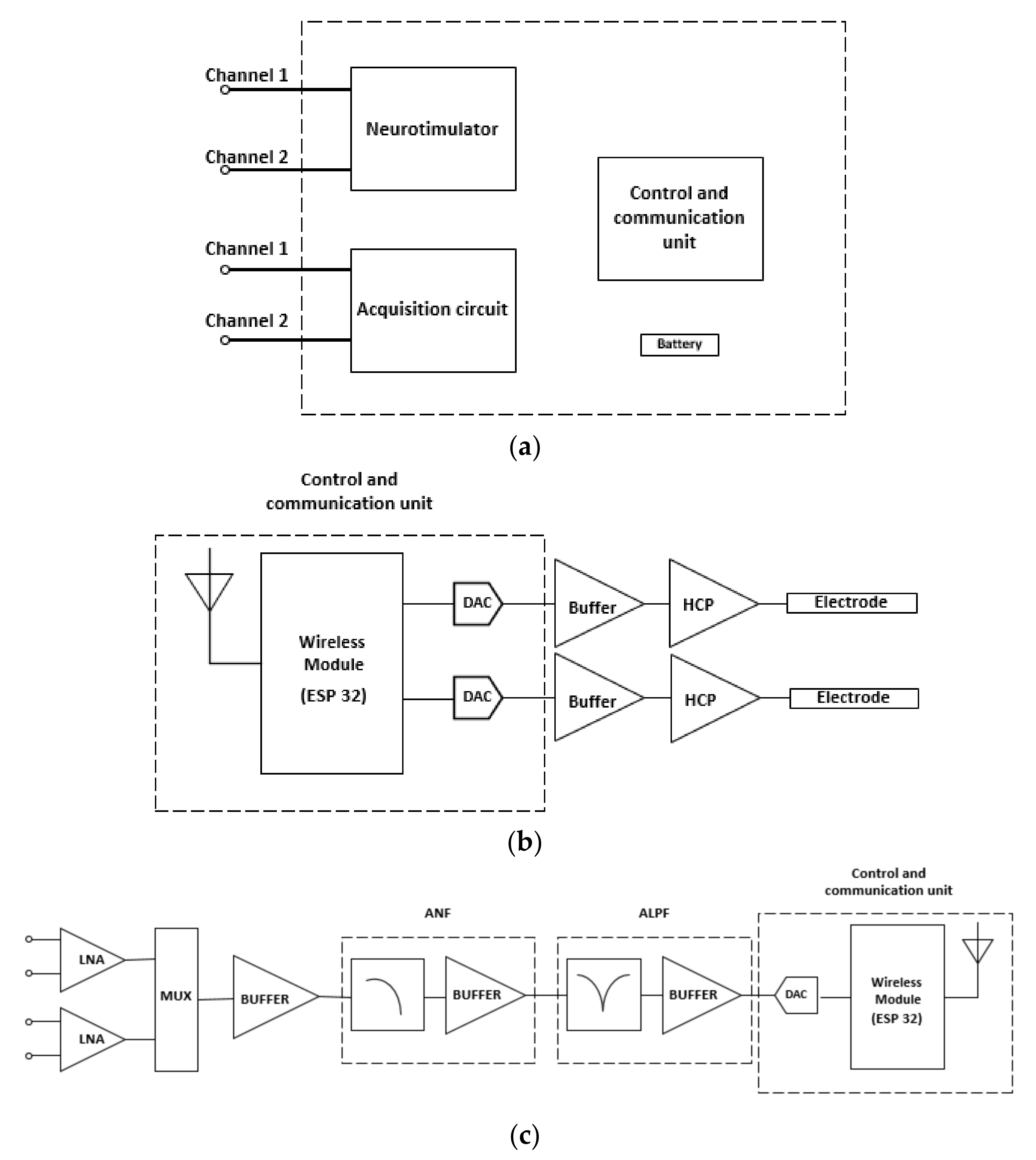
2. Proposed Design
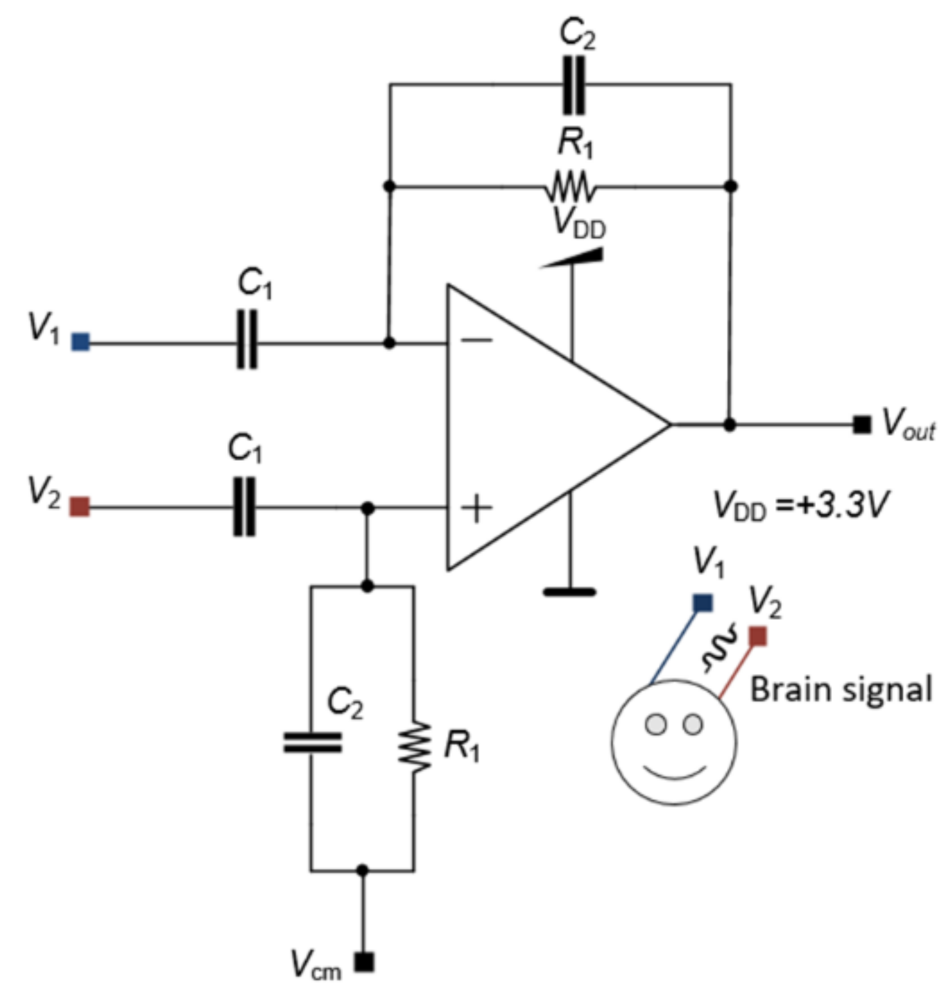
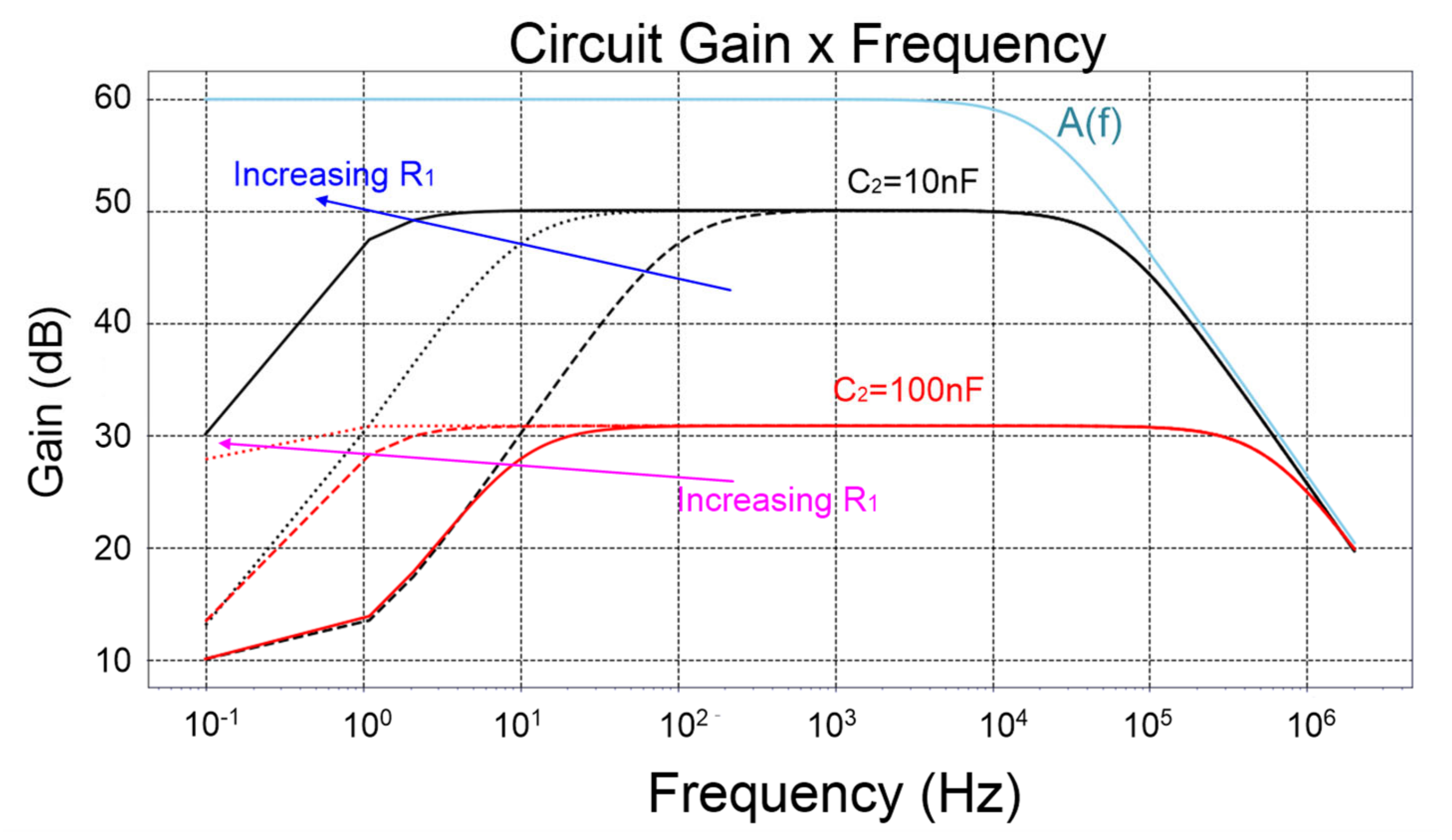
2.1. Low-Noise Amplifier (LNA)
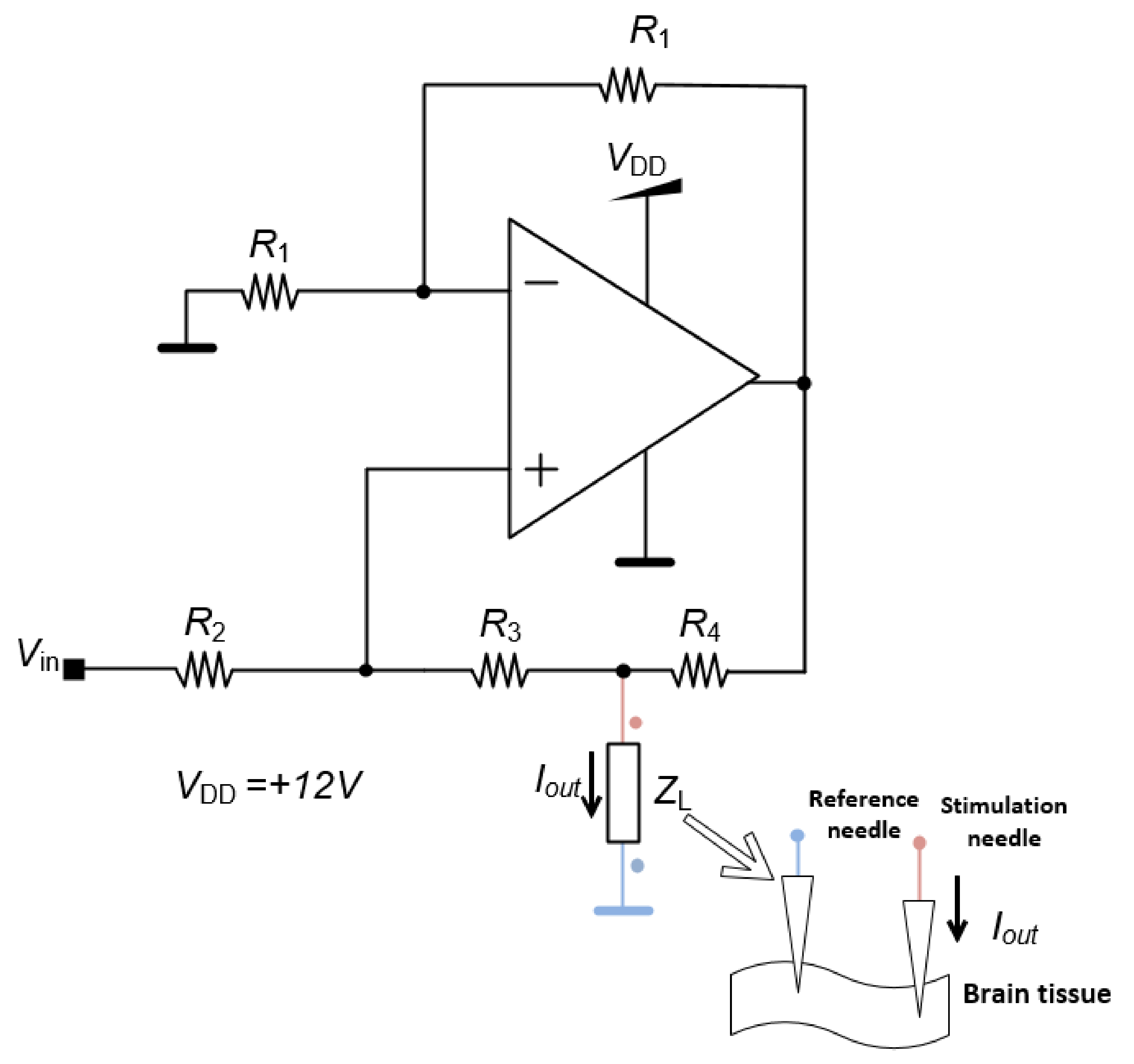
2.2. Neurostimulator
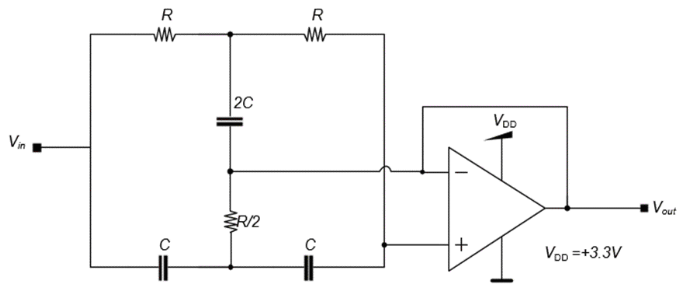
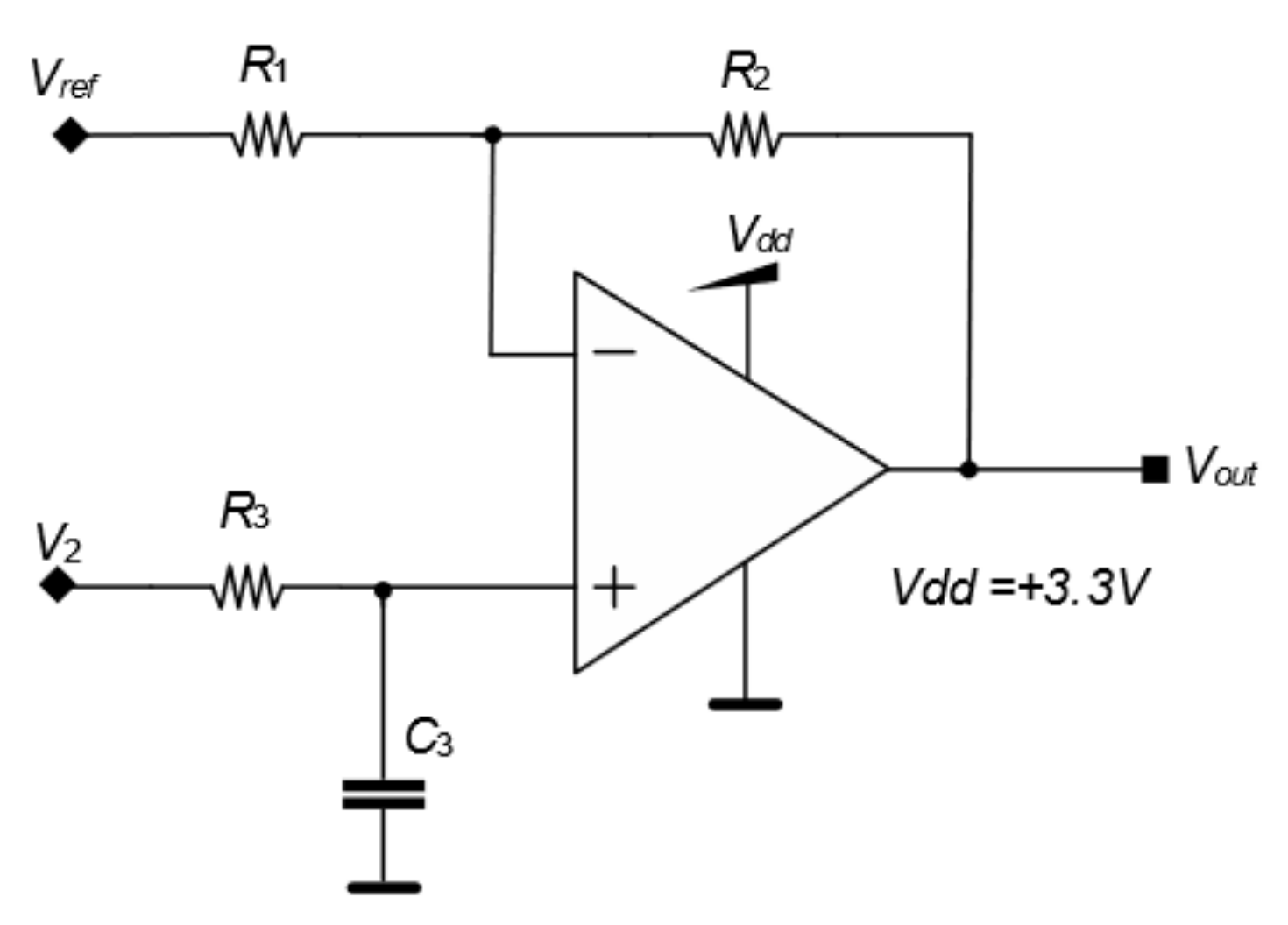
2.3. Acquisition Circuit
2.4. Control and Communication Unit
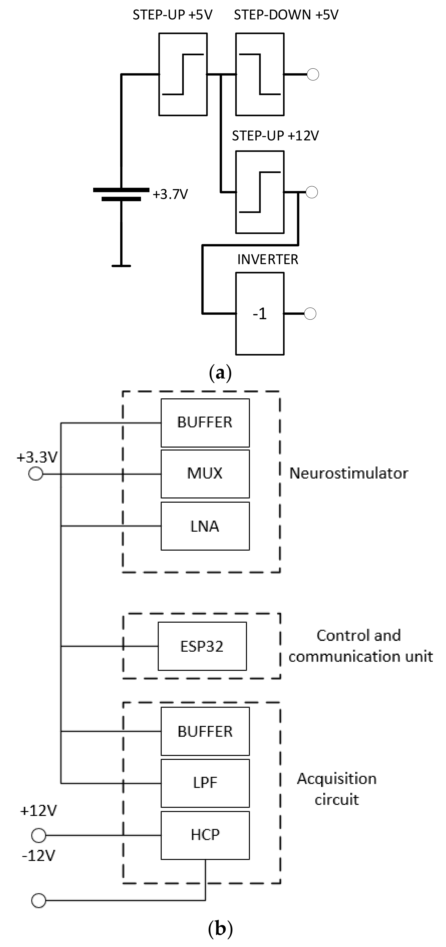
2.5. Energy Control
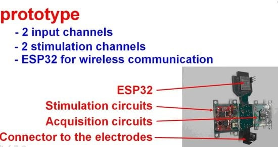
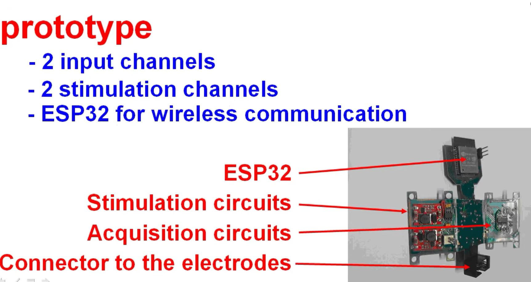
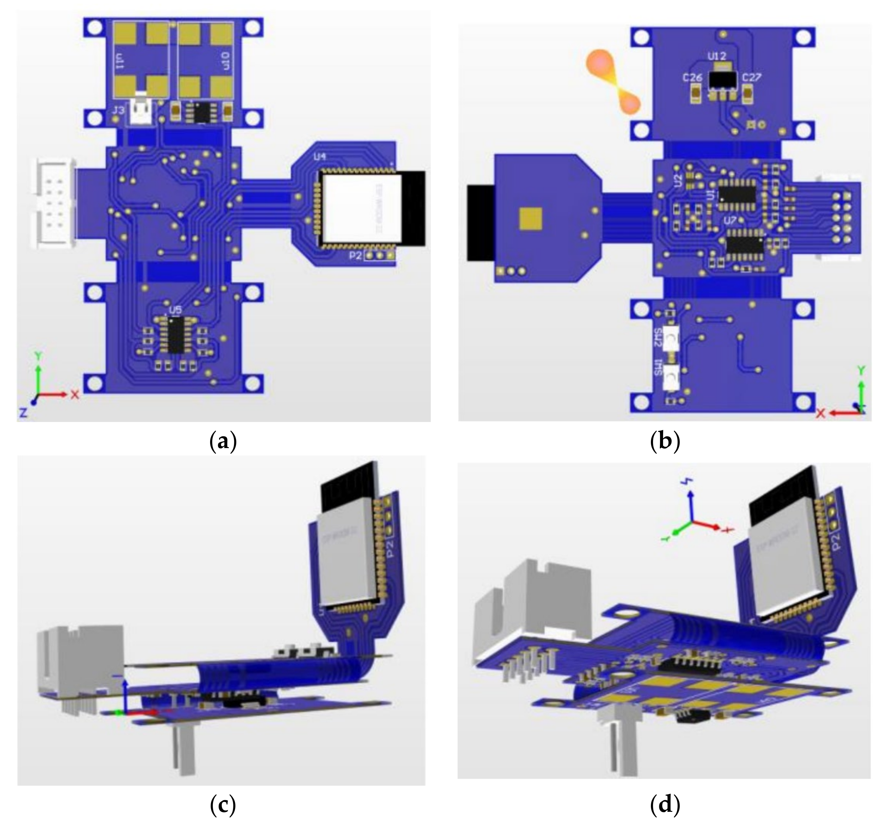
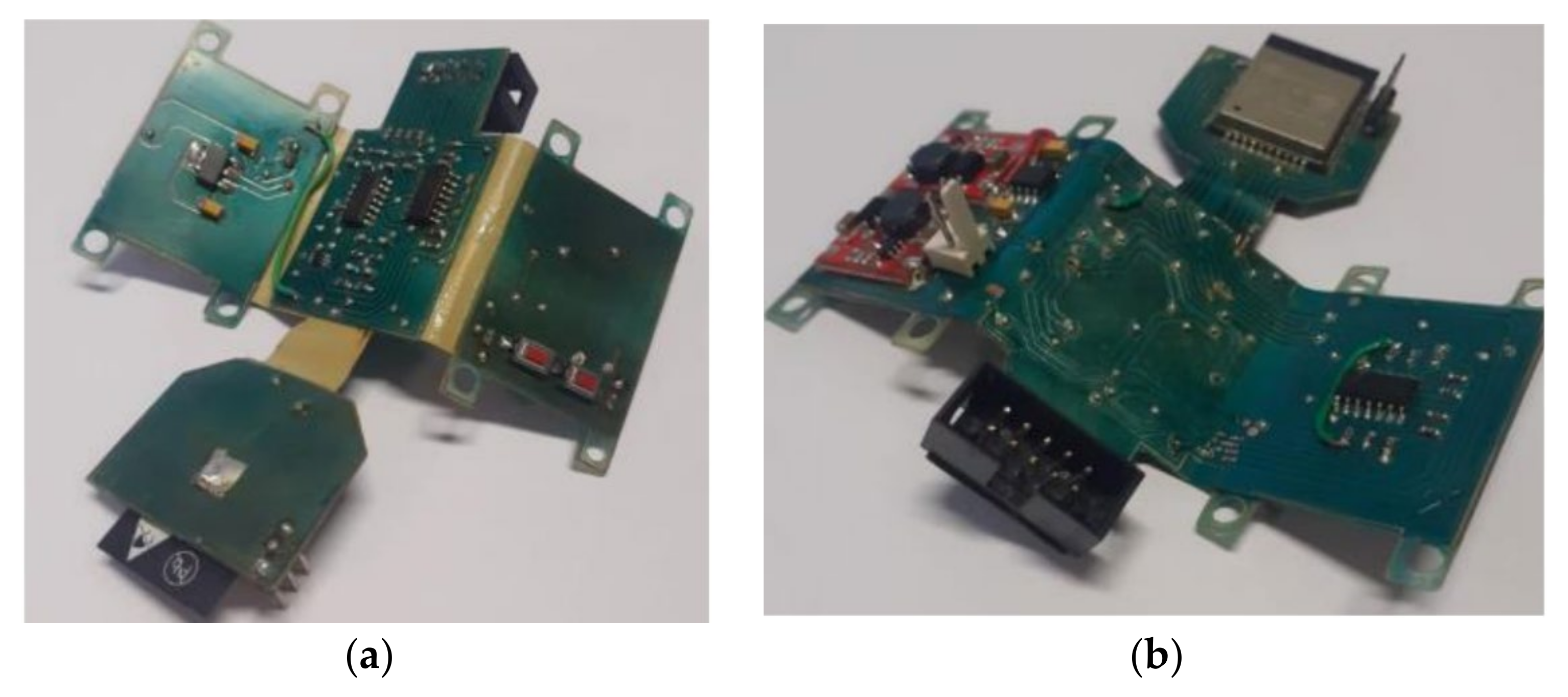
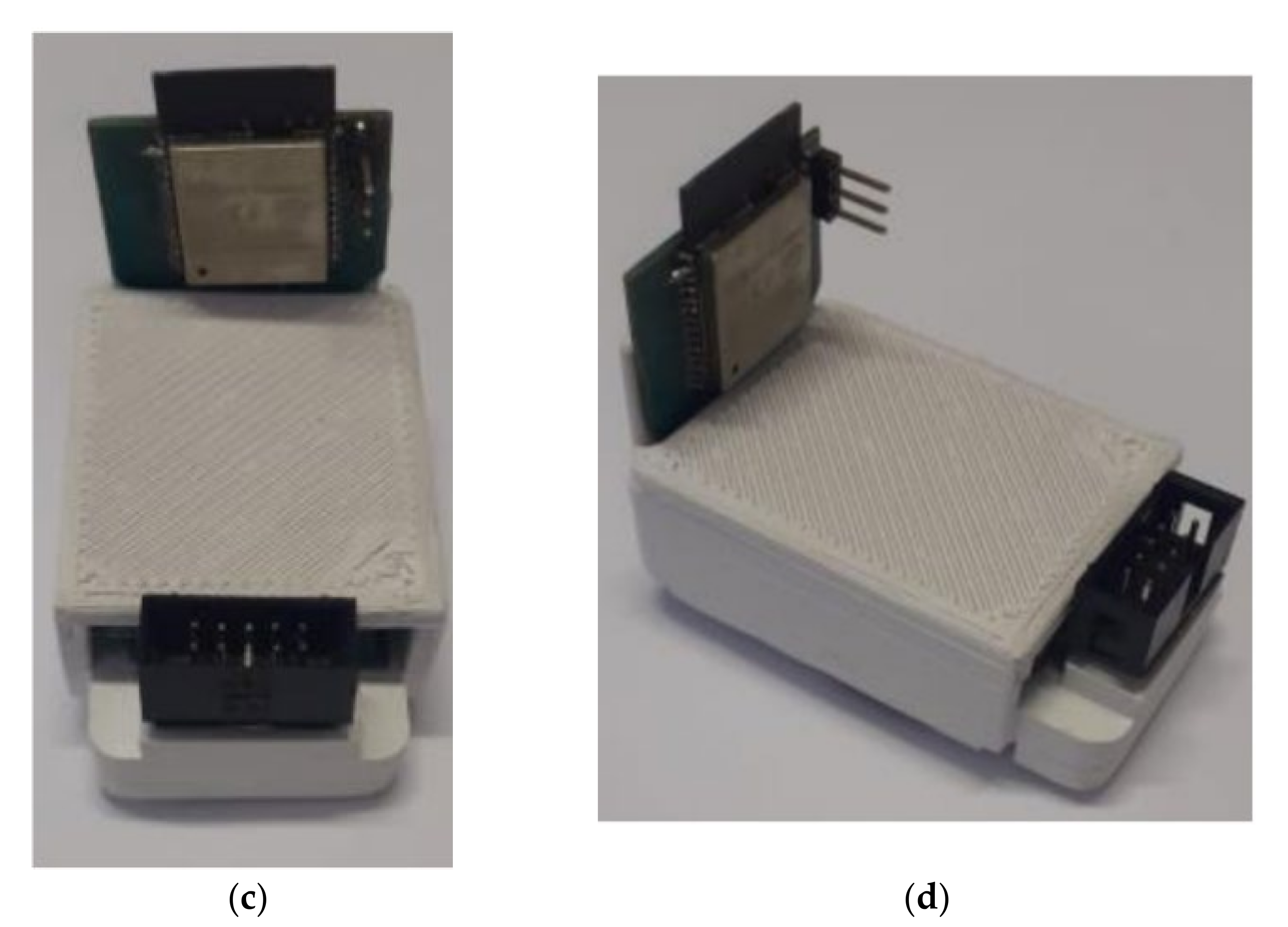
2.6. Prototype
3. Experimental Results
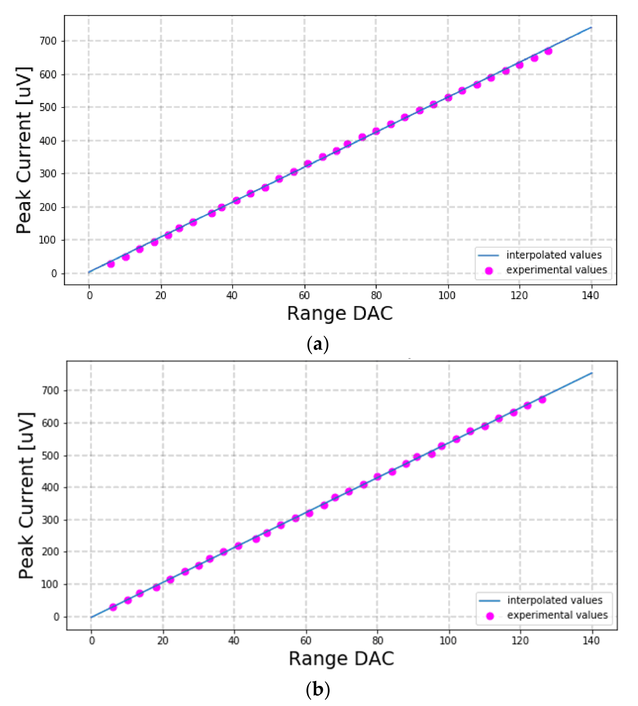
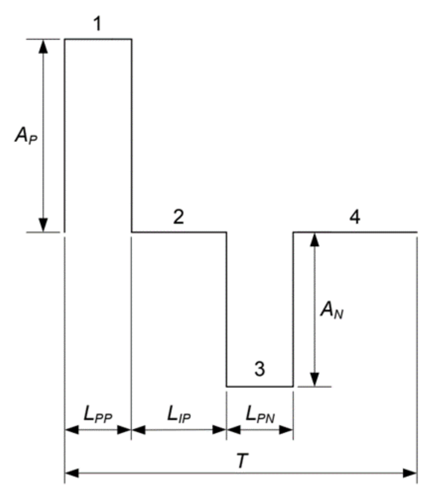
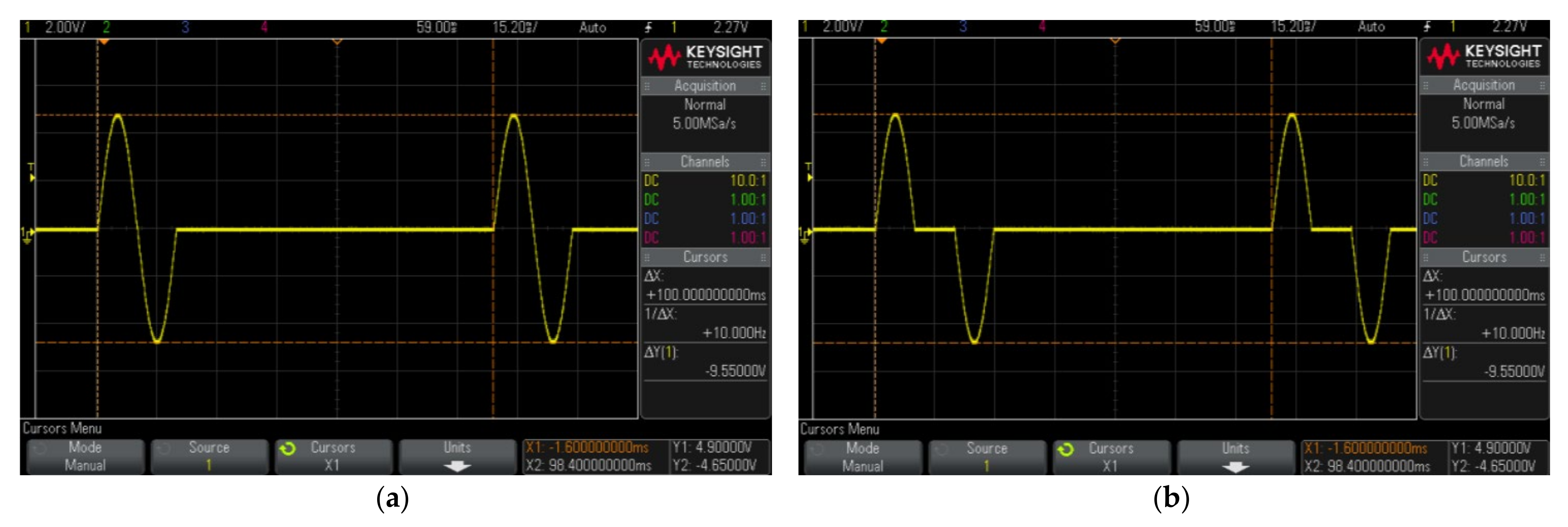
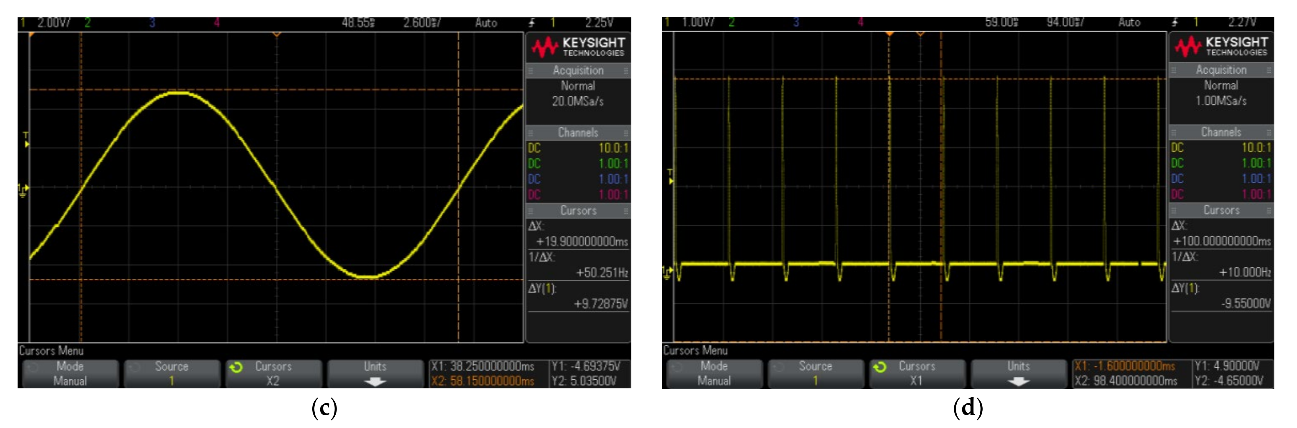
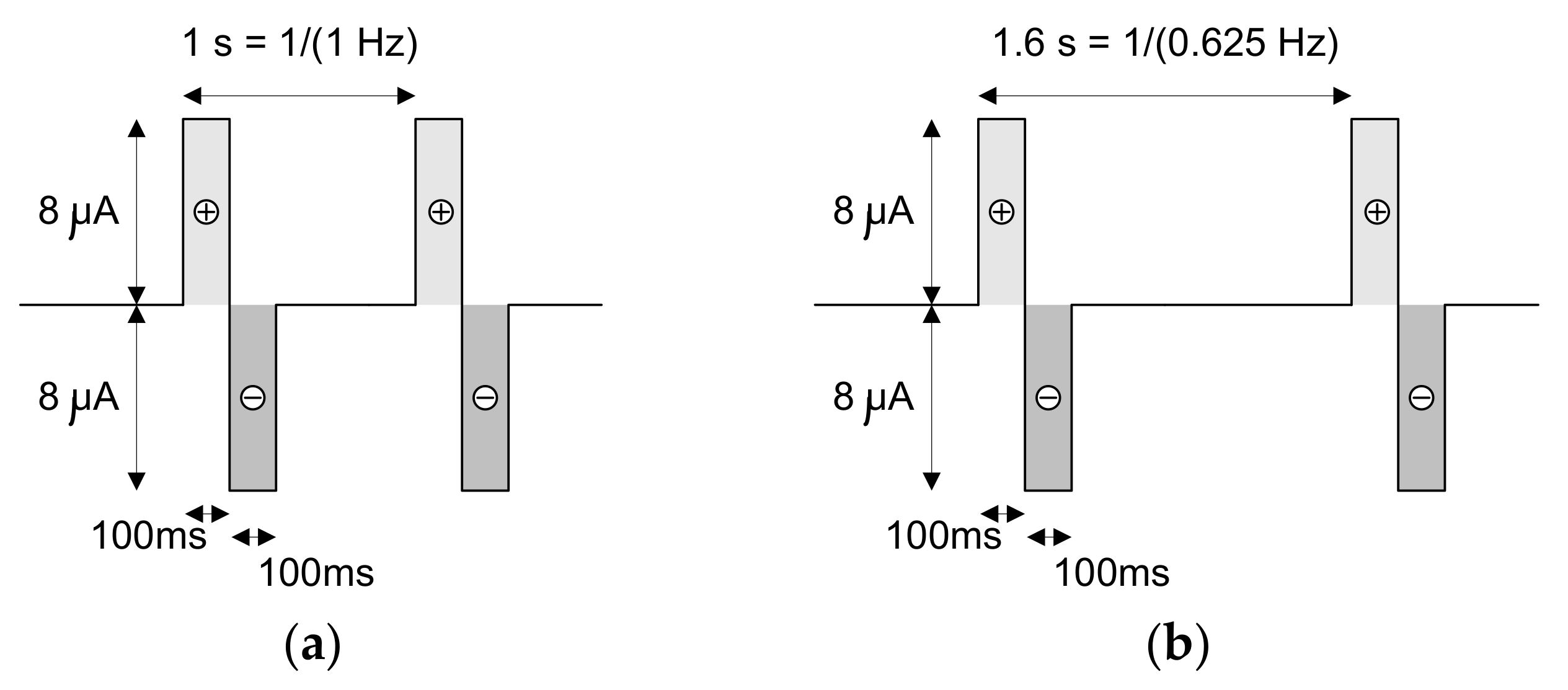
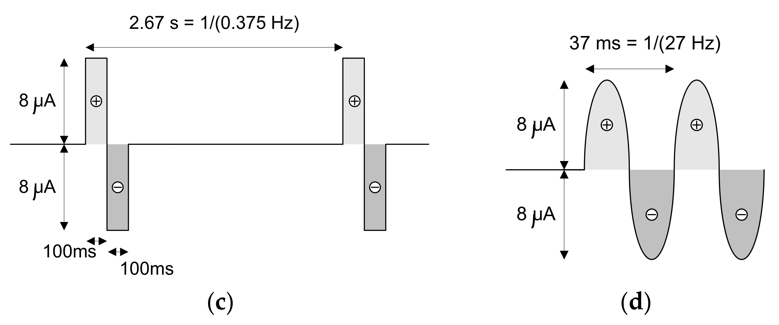
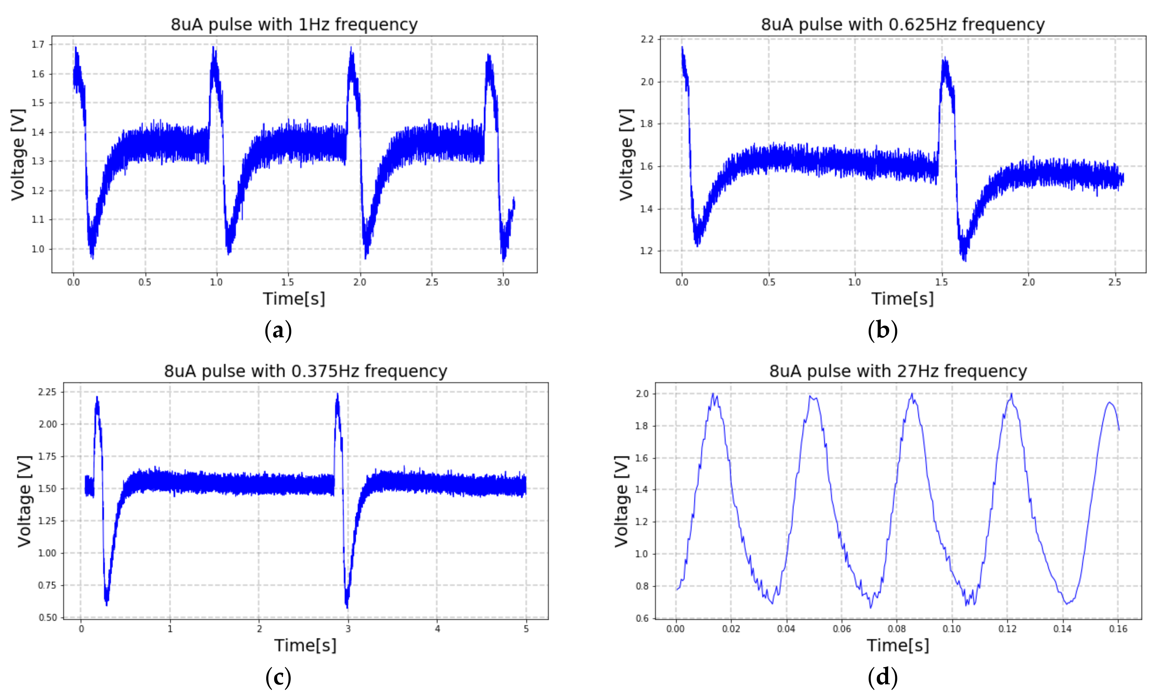
3.1. Neurostimulator
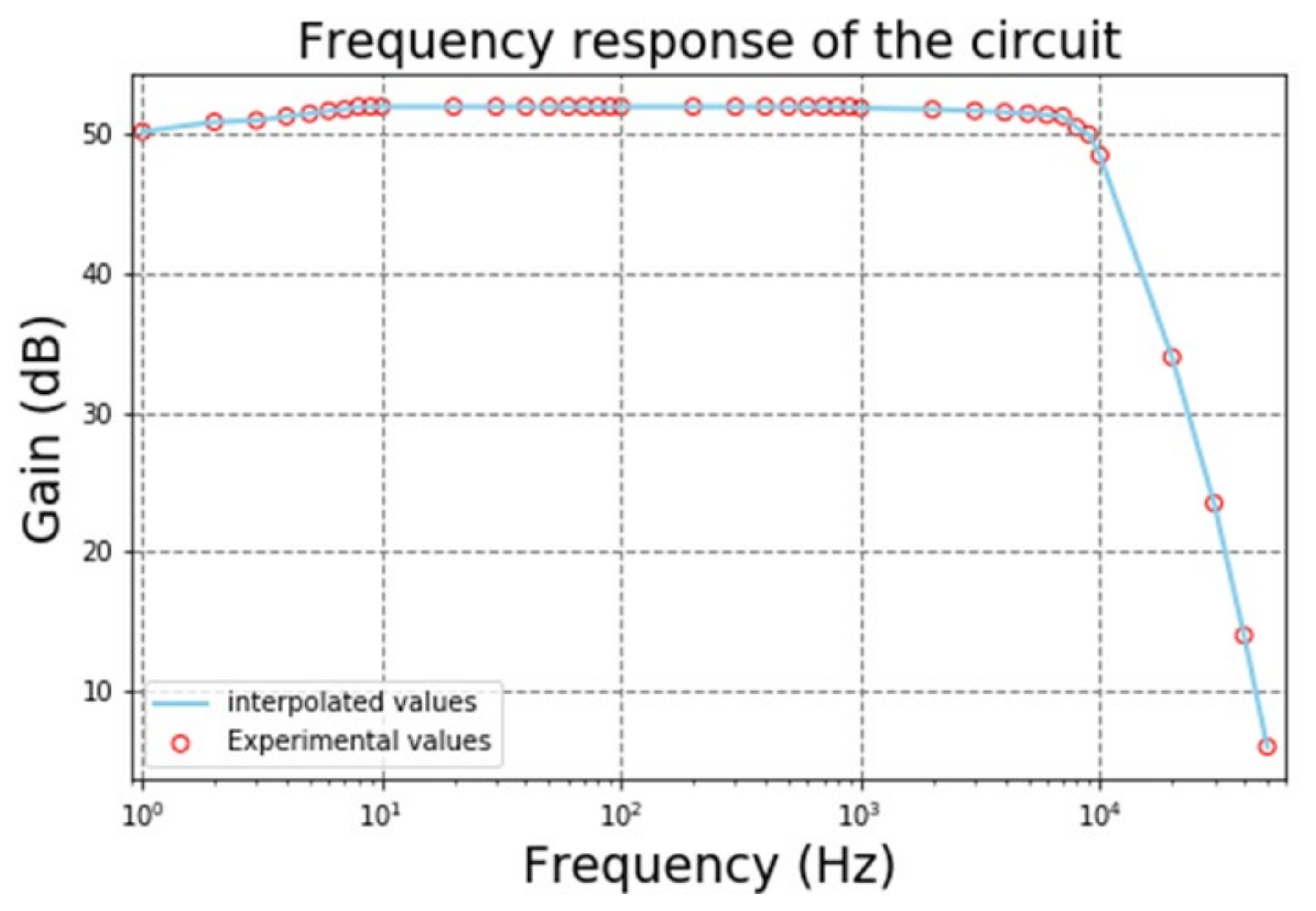
3.2. Acquisition System
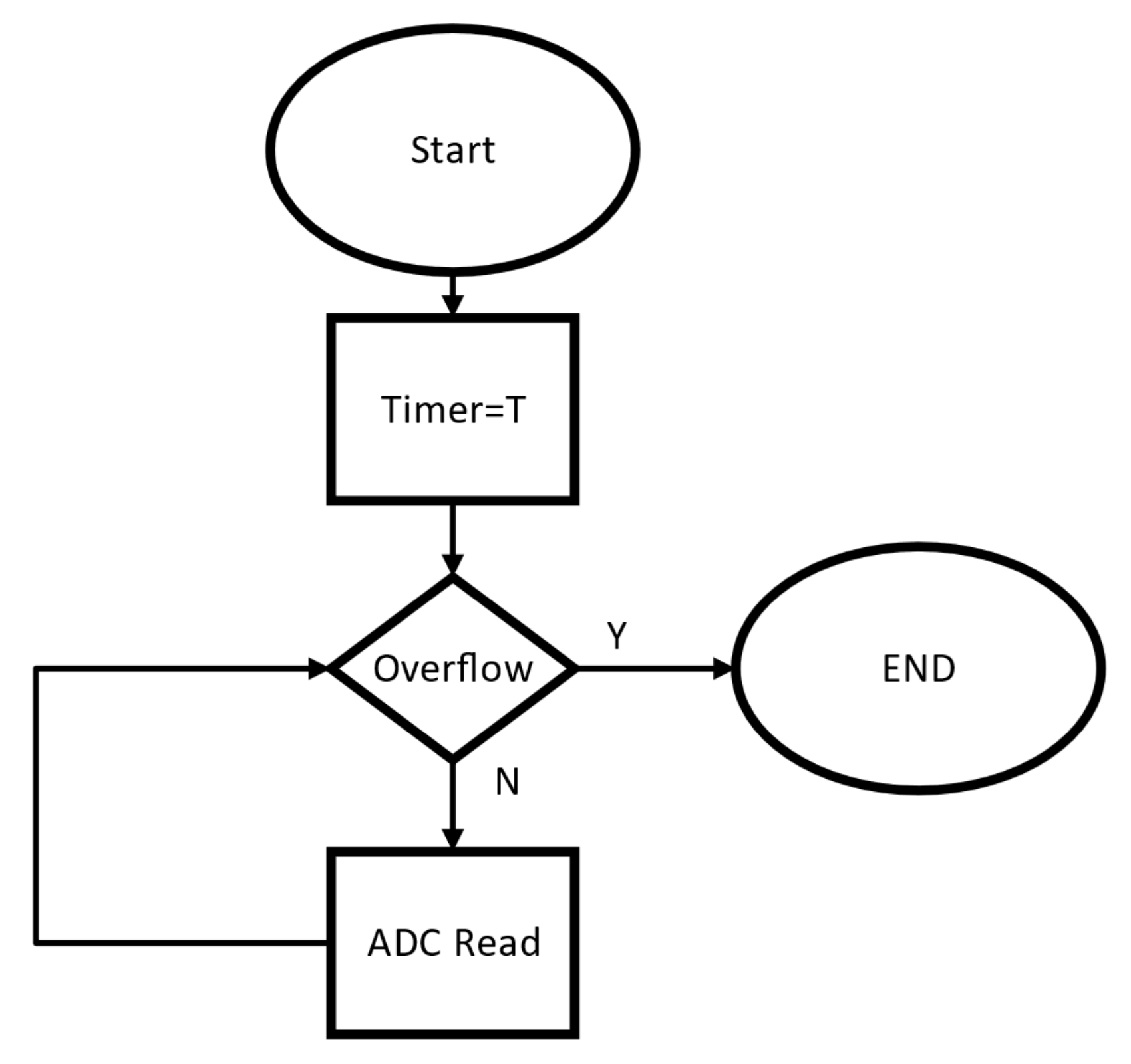
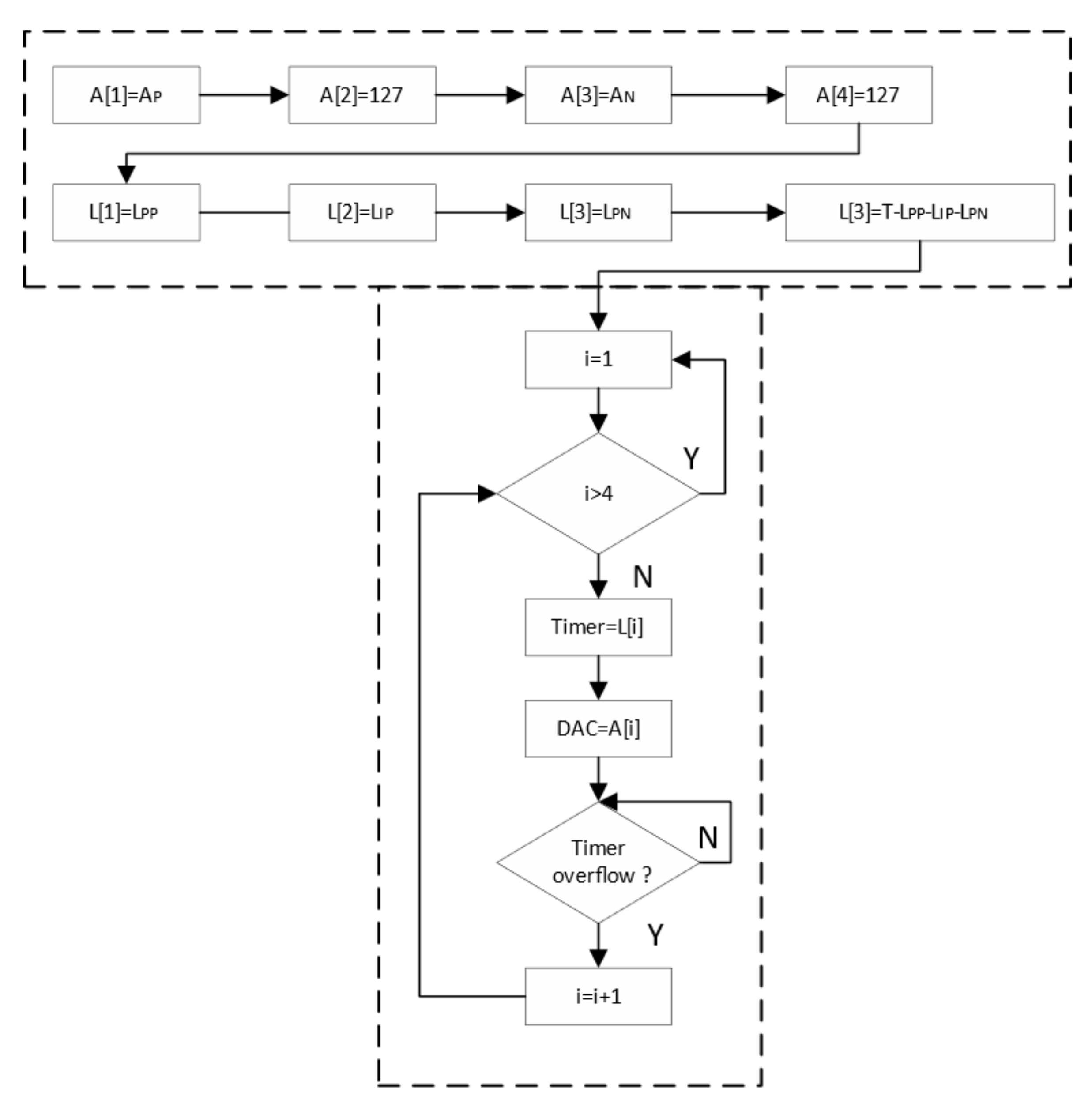
3.3. Software Implementation
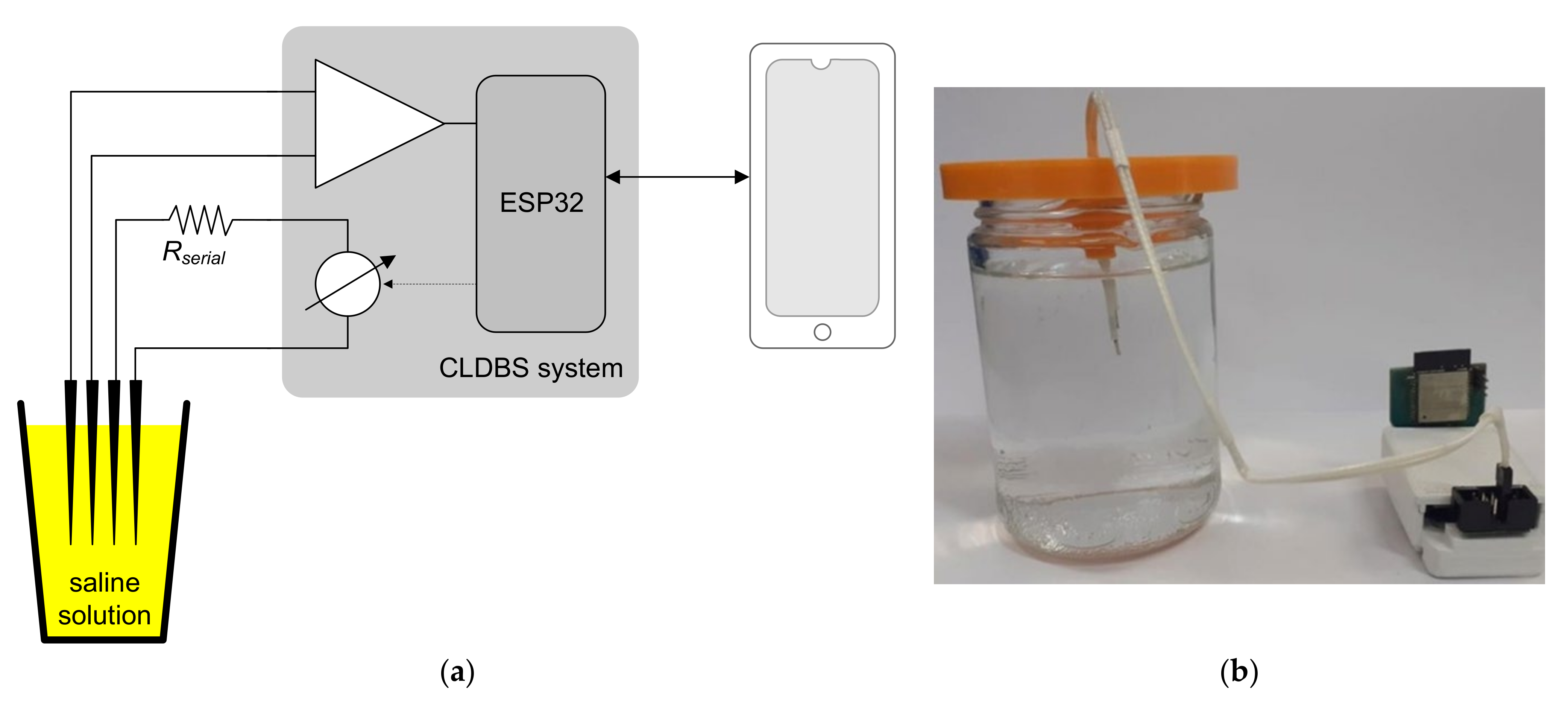
3.4. Closed-Loop Ex-Vivo Tests
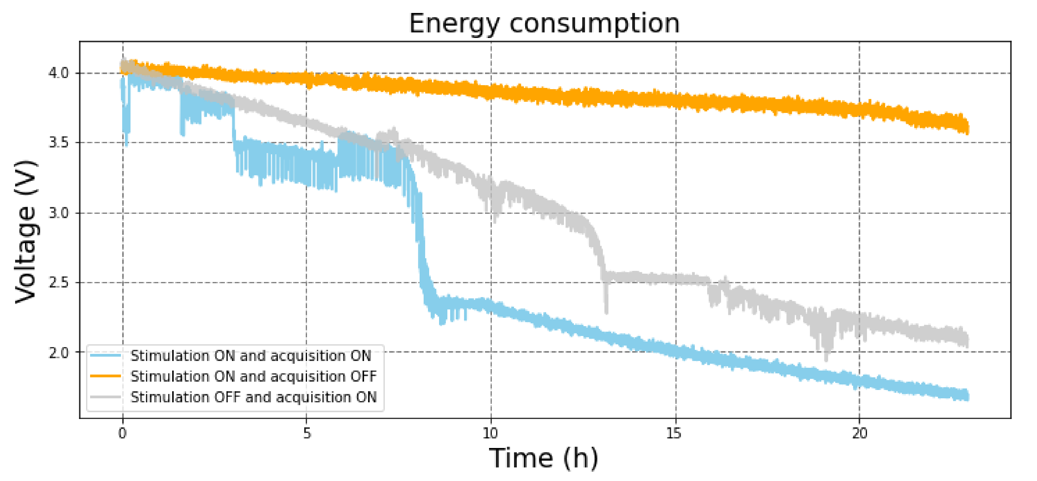
3.5. Power Consumption Tests
3.6. Comparison with the State-of-the-Art
4. Conclusions
Author Contributions
Funding
Conflicts of Interest
References
- Mayfield Clinic. Deep Brain Stimulation for Movement Disorders. Mayfield Clinic. 2018. Available online: https://mayfieldclinic.com/pe-dbs.htm (accessed on 10 July 2023).
- Hickey, P.; Stacy, M. Deep brain stimulation: A paradigm shifting approach to treat Parkinson’s disease. Front. Neurosci. 2016, 10, 173. [Google Scholar] [CrossRef] [PubMed]
- Bittar, R.G.; Burn, S.C.; Bain, P.G.; Owen, S.L.; Joint, C.; Shlugman, D.; Aziz, T.Z. Deep brain stimulation for movement disorders and pain. J. Clin. Neurosci. 2005, 12, 457–463. [Google Scholar] [CrossRef]
- Cury, R.G.; Galhardoni, R.; Fonoff, E.T.; Lloret, S.P.; Ghilardi, M.G.S.; Barbosa, E.R.; Teixeira, M.J.; de Andrade, D.C. Sensory abnormalities and pain in Parkinson disease and its modulation by treatment of motor symptoms. Eur. J. Pain 2016, 20, 151–165. [Google Scholar] [CrossRef] [PubMed]
- Rehncrona, S.; Johnels, B.; Widner, H.; Törnqvist, A.L.; Hariz, M.; Sydow, O. Long-term efficacy of thalamic deep brain stimulation for tremor: Double blind assessments. Mov. Disord. 2003, 18, 163–170. [Google Scholar] [CrossRef]
- Ghilardi, M.G.S.; Ibarra, M.; Alho, E.J.L.; Reis, P.R.; Contreras, W.O.L.; Hamani, C.; Fonoff, E.T. Double-target DBS for essential tremor: 8-contact lead for cZI and Vim aligned in the same trajectory. Neurology 2018, 90, 476–478. [Google Scholar] [CrossRef] [PubMed]
- Fonoff, E.T.; Ghilardi, M.G.S.; Cury, R.G. Neurocirurgia funcional para o Clínico: Estimulação Cerebral Profunda em Doença de Parkinson, Distonia e Outros Distúrbios do movimento. In Capítulo de Livro, Condutas em Neurologia, 11th ed.; Nitrini, R., Ed.; Manole Editora: Sao Paulo, Brazil, 2016; pp. 53–67. (In Portuguese) [Google Scholar]
- Vidailhet, M.; Vercueil, L.; Houeto, J.L.; Krystkowiak, P.; Benabid, A.L.; Cornu, P.; Lagrange, C.; Tézenas du Montcel, S.; Dormont, D.; Grand, S.; et al. Bilateral deep-brain stimulation of the globus pallidus in primary generalized dystonia. N. Engl. J. Med. 2005, 352, 459–467. [Google Scholar] [CrossRef] [PubMed]
- Owen, S.L.; Green, A.L.; Stein, J.F.; Aziz, T.Z. Deep brain stimulation for the alleviation of poststroke neuropathic pain. Pain 2006, 120, 202–206. [Google Scholar] [CrossRef] [PubMed]
- Marchand, S.; Kupers, R.C.; Bushnell, M.C.; Duncan, G.H. Analgesic and placebo effects of thalamic stimulation. Pain 2003, 105, 481–488. [Google Scholar] [CrossRef]
- Gadot, R.; Najera, R.; Hiran, S.; Anand, A.; Storch, E.; Goodman, W.K.; Shofty, B.; Sheth, S.A. Efficacy of deep brain stimulation for treatment-resistant obsessive-compulsive disorder: Systematic review and meta-analysis. J. Neurol. Neurosurg. Psychiatry 2022, 93, 1166–1173. [Google Scholar] [CrossRef]
- Franco, R.; Fonoff, E.T.; Alvarenga, P.; Lopes, A.C.; Miguel, E.C.; Teixeira, M.J.; Damiani, D.; Hamani, C. DBS for Obesity. Brain Sci. 2016, 6, 21. [Google Scholar] [CrossRef]
- Drobisz, D.; Damborská, A. Deep brain stimulation targets for treating depression. Behav. Brain Res. 2019, 359, 266–273. [Google Scholar] [CrossRef] [PubMed]
- Figee, M.; Riva-Posse, P.; Choi, K.S.; Bederson, L.; Mayberg, H.S.; Kopell, B.H. Deep Brain Stimulation for Depression. Neurotherapeutics 2022, 19, 1229–1245. [Google Scholar] [CrossRef] [PubMed]
- Sheth, S.A.; Bijanki, K.R.; Metzger, B.; Allawala, A.; Pirtle, V.; Adkinson, J.A.; Myers, J.; Mathura, R.K.; Oswalt, D.; Tsolaki, E.; et al. Deep Brain Stimulation for Depression Informed by Intracranial Recordings. Biol. Psychiatry 2022, 92, 246–251. [Google Scholar] [CrossRef] [PubMed]
- Hoang, K.B.; Cassar, I.R.; Grill, W.M.; Turner, D.A. Biomarkers and stimulation algorithms for adaptive brain stimulation. Front. Neurosci. 2017, 11, 564. [Google Scholar] [CrossRef] [PubMed]
- Bouthour, W.; Mégevand, P.; Donoghue, J.; Lüscher, C.; Birbaumer, N.; Krack, P. Biomarkers for closed-loop deep brain stimulation in Parkinson disease and beyond. Nat. Rev. Neurol. 2019, 15, 343–352. [Google Scholar] [CrossRef] [PubMed]
- AN-1515, A Comprehensive Study of the Howland Current Pump, 26 April 2013, Texas Instruments. Available online: https://www.ti.com/lit/an/snoa474a/snoa474a.pdf (accessed on 10 July 2023).
- Nordi, T.M.; Barbosa, V.M.; Gounella, R.H.; Assan, G.; Luppe, M.; Junior, J.N.S.; Carmo, J.P.; Fonoff, E.T.; Colombari, E. Charge Pump Circuit in 65nm CMOS for Neural Stimulation on Deep Brain Stimulation. In Proceedings of the XXXVI Conference on Design of Circuits and Integrated Circuits (DCIS 2021), Vila do Conde, Portugal, 24–26 November 2021. [Google Scholar]
- Štanfel, D.; Kalogjera, L.; Ryazantsev, S.V.; Hlača, K.; Radtsig, E.Y.; Teimuraz, R.; Hrabač, P. The Role of Seawater and Saline Solutions in Treatment of Upper Respiratory Conditions. Mar. Drugs 2022, 20, 330. [Google Scholar] [CrossRef]
- Kölbl, F.; N’Kaoua, G.; Naudet, F.; Berthier, F.; Faggiani, E.; Renaud, S.; Benazzouz, A.; Lewis, N. An Embedded Deep Brain Stimulator for Biphasic Chronic Experiments in Freely Moving Rodents. IEEE Trans. Biomed. Circuits Syst. 2016, 10, 72–84. [Google Scholar] [CrossRef]
- Pinnell, R.C.; de Vasconcelos, A.P.; Cassel, J.C.; Hofmann, U.G. A miniaturized programmable deep-brain stimulator for group-housing and water maze use. Front. Neurosci. 2018, 12, 231. [Google Scholar] [CrossRef] [PubMed]
- Ewing, S.G.; Lipski, W.J.; Grace, A.A.; Winter, C. An inexpensive charge-balanced rodent deep brain stimulation device a step-by-step guide to its procurement and construction. J. Neurosci. Methods 2013, 219, 324–330. [Google Scholar] [CrossRef] [PubMed]
- Kouzani, A.Z.; Abulseoud, O.A.; Tye, S.J.; Hosain, M.D.K.; Berk, M. A low power micro deep brain stimulation device for murine preclinical research. IEEE J. Translacional Eng. Health Med. 2013, 1, 1500109. [Google Scholar] [CrossRef] [PubMed]
- Ewing, S.G.; Porr, B.; Riddell, J.; Winter, C.; Grace, A.A. SaBer DBS: A fully programmable, rechargeable, bilateral, charge;balanced preclinical microstimulator for long-term neural stimulation. J. Neurosci. Methods 2013, 213, 228–235. [Google Scholar] [CrossRef] [PubMed]
- Adams, S.D.; Bennet, K.E.; Tye, S.J.; Berk, M.; Kouzani, A.Z. Development of a miniature device for emerging deep brain stimulation paradigms. PLoS ONE 2019, 14, e0212554. [Google Scholar] [CrossRef] [PubMed]
- Tibara, H.; Naudeta, F.; Kölblc, F.; Ribota, B.; Faggiania, E.; Kaouac, G.N.; Renaudc, S.; Lewisc, N.; Benazzouza, A. In vivo validation of a new portable stimulator for chronic deep brain stimulation in freely moving rats. J. Neurosci. Methods 2020, 333, 108577. [Google Scholar] [CrossRef] [PubMed]
- Fluri, F.; Mützel, T.; Schuhmann, M.K.; Krstić, M.; Endres, H.; Volkmann, J. Development of a head-mounted wireless microstimulator for deep brain stimulation in rats. J. Neurosci. Methods 2017, 291, 249–256. [Google Scholar] [CrossRef] [PubMed]
- Pinnell, R.C.; Dempster, J.; Pratt, J. Miniature wireless recording and stimulation system for rodent behavioural testing. J. Neural Eng. 2015, 12, 066015. [Google Scholar] [CrossRef] [PubMed]


| Ref. | Number of Channels Acquisition/Stimulation | Stimulation Current [μA] | Maximum Pulse Frequency [Hz]/ Minimum Pulse Duration [ms] | Stimulation Form | System Size |
|---|---|---|---|---|---|
| This work | 2/2 | −325 to +318 | 1.5 × 10⁶/25 | Active/Continuous (Howland Current-Pump) | 58 mm × 37 mm × 29 mm |
| [22] | 2 * | 20 to 2000 | 500/10 | Active/Switched (H-bridge) | 12.5 diameter × 5 mm |
| [23] | 2 * | −200 to +200 | 185/90 | Active/Switched | 24 mm × 16.8 mm |
| [24] | 2 * | 0 to 200 | 130/90 | Passive/Switched | 12.5 diameter |
| [25] | 2 * | 13 to 1000 | 500/24 | Active/Switched | 3 mm × 20 mm × 8 mm |
| [26] | 1 * | −375 to +250 | 5000/20 | Active/Continuous (Howland Current-Pump) | 32.5 mm × 28 mm × 8 mm |
| [27] | 1 * | 20 to 2000 | 300/40 | Active/Switched (H-bridge) | 22.2 mm × 32.8 mm × 23 mm |
| [28] | 1 * | 10 to 500 | 200/60 | Passive/Switched | 21 mm × 11 mm × 7 mm |
| [29] | 4/2 | 30-1500 | 5 × 10³/0.01 | Active/Constant Current-Generator | 28 × 17 × 7 mm |
Disclaimer/Publisher’s Note: The statements, opinions and data contained in all publications are solely those of the individual author(s) and contributor(s) and not of MDPI and/or the editor(s). MDPI and/or the editor(s) disclaim responsibility for any injury to people or property resulting from any ideas, methods, instructions or products referred to in the content. |
© 2023 by the authors. Licensee MDPI, Basel, Switzerland. This article is an open access article distributed under the terms and conditions of the Creative Commons Attribution (CC BY) license (https://creativecommons.org/licenses/by/4.0/).
Share and Cite
Matheus Nordi, T.; Augusto Ginja, G.; Gounella, R.; Talanoni Fonoff, E.; Colombari, E.; Moreira, M.M.A.; Afonso, J.A.; Monteiro, V.; Afonso, J.L.; Carmo, J.P. Wireless Device with Energy Management for Closed-Loop Deep Brain Stimulation (CLDBS). Electronics 2023, 12, 3082. https://doi.org/10.3390/electronics12143082
Matheus Nordi T, Augusto Ginja G, Gounella R, Talanoni Fonoff E, Colombari E, Moreira MMA, Afonso JA, Monteiro V, Afonso JL, Carmo JP. Wireless Device with Energy Management for Closed-Loop Deep Brain Stimulation (CLDBS). Electronics. 2023; 12(14):3082. https://doi.org/10.3390/electronics12143082
Chicago/Turabian StyleMatheus Nordi, Tiago, Gabriel Augusto Ginja, Rodrigo Gounella, Erich Talanoni Fonoff, Eduardo Colombari, Melkzedekue M. Alcântara Moreira, Jose A. Afonso, Vitor Monteiro, Joao L. Afonso, and João Paulo Carmo. 2023. "Wireless Device with Energy Management for Closed-Loop Deep Brain Stimulation (CLDBS)" Electronics 12, no. 14: 3082. https://doi.org/10.3390/electronics12143082
APA StyleMatheus Nordi, T., Augusto Ginja, G., Gounella, R., Talanoni Fonoff, E., Colombari, E., Moreira, M. M. A., Afonso, J. A., Monteiro, V., Afonso, J. L., & Carmo, J. P. (2023). Wireless Device with Energy Management for Closed-Loop Deep Brain Stimulation (CLDBS). Electronics, 12(14), 3082. https://doi.org/10.3390/electronics12143082