Abstract
The traditional radial flux PMSM and axial flux PMSM have an effective air gap on only one side, between the stator and rotor, and only the effective air gap generates electromagnetic torque. There are defects in the magnetic-field utilization, and it is difficult to improve the torque density. Therefore, this paper proposes an axial–radial-flux permanent-magnet synchronous motor (ARF-PMSM), which combines radial flux with axial flux, to be used in an elevator-traction machine-drive motor. The characteristics of the ARF-PMSM are that the stator core is made of a soft magnetic composite material and the winding is annular. The motor has three effective air gaps, which can achieve high torque density without increasing the overall dimensions. In this paper, the mechanical structure and operation mechanism of the ARF-PMSM are introduced, and the characteristics of its magnetic circuit structure are analyzed by using the equivalent magnetic circuit method. The torque characteristics and other electromagnetic characteristics of the ARF-PMSM, the traditional surface-mounted PMSM, and the spoke-type PMSM are compared and analyzed using the finite element method. The research results show that the proposed motor has high torque density, which provides a new design idea in the form of a high-torque-density PMSM for use in elevator-traction machines.
1. Introduction
Fractional slot concentrated winding permanent-magnet motors have become a focus of research both in China and abroad due to their advantages of high torque density, simple winding structure, small cogging torque, and high efficiency, and they are widely used in direct-drive systems, such as CNC machine-tool turntables, aerospace, mining machinery, and robot-elbow joints [1,2,3,4]. The low-speed and high-torque PMSM is the mainstream model of elevator-traction machine at present. It can directly drive the traction wheel without intermediate transmission links, such as reducers, which improves the transmission efficiency and reliability of the elevator system. High torque density and low torque fluctuation are the goals of permanent-magnet synchronous-traction machines.
In recent years, with the application of new technologies and processes, elevator-traction machine products have been constantly updated and iterated. The improvement in the utilization of materials and the reduction in manufacturing costs have reached a limit. However, the traditional radial-flux PMSM and axial-flux PMSM have an effective air gap on one side only, between the stator and the rotor, and only the effective air gap generates electromagnetic torque, which causes defects in the utilization of magnetic-field space and makes it difficult to improve the torque density. Therefore, it is necessary to develop a new type of high-torque-density permanent-magnet synchronous-traction machine to improve upon the existing situation. At present, in order to improve the torque density, traditional radial-flux permanent-magnet synchronous-traction machines mostly adopt a flat structure with a large diameter-to-length ratio (the ratio of the stator-core diameter to its axial length), that is, the axial core is short, which leads to a large proportion of the copper volume at the end of the winding in the overall winding volume, while the end of the motor winding does not participate in electromechanical energy conversion, which wastes raw materials and reduces the efficiency of the motor. If the end windings can be utilized by changing the topological structure of the motor and the electromechanical energy-conversion area can be increased at the same time, the torque density of the motor can be greatly improved. In addition, in order to reduce the eddy-current loss in the stator core, the stator core of the radial-flux PMSM is mostly made of silicon-steel sheets using axial lamination, and the stator core of the axial flux PMSM is mostly composed of silicon-steel sheets wound along the radial direction, which limits the path direction of its main magnetic flux—that is, the main magnetic circuit of the radial-flux motor is closed along the radial direction, and the main magnetic circuit of the axial-flux motor is closed along the axial direction, which means that the application of a silicon-steel sheet in a three-dimensional magnetic-flux motor with a relatively complex magnetic-circuit structure has certain limitations.
Based on the problems above, an axial–radial-flux permanent-magnet synchronous motor (ARF-PMSM) with annular winding for an elevator-traction machine is proposed in this paper. It is characterized by the fact that the stator core is made out of a soft magnetic composite (SMC) material, which solves the problem of the difficult manufacturing of a complexly shaped stator. The stator winding adopts an annular winding structure, and the winding has no end. It can intersect with the radial rotor’s magnetic field and the two axial rotors’ magnetic fields to generate electromagnetic torque, and it can shorten the axial length of the motor-stator core. The motor has a three-side effective air-gap magnetic field and makes full use of the isotropic characteristics of the magnetic properties of the SMC material. The axial flux and radial flux are combined to achieve high torque density in the ARF-PMSM without increasing the overall size. At the same time, the utilization rate of the stator-core material and motor space is improved.
High torque density and low torque ripple are urgently needed for the direct-drive, low-speed operation of PMSM for elevator-traction machines. For surface permanent magnet motors (SPMs), the air-gap permeance is almost constant due to the relative permeability of PMs, which is almost equal to unity; hence, sinusoidal air-gap flux density can be achieved by shaping PMs to achieve low torque ripple [5,6,7], but the torque density is usually considerably compromised. Although the use of rare-earth permanent-magnet materials with greater magnetic properties is a method to improve the torque density of PMSM, there are other design methods that can further improve the torque performance. For realizing a magnetic field offset through symmetrical permanent magnets and asymmetrical-rotor magnetic barriers, Zhao et al. used symmetrical V-shaped permanent magnets and added a “—”-type magnetic barrier on the right side of the V-shaped permanent magnet slot. Compared with the original permanent magnet motor with a pure V-shaped permanent-magnet-slot structure, the total torque increased by 16.6%, and the torque density increased significantly [8]. In [9], a design-and-analysis method for a novel hybrid flux permanent magnet (PM) machine for high-power density is presented. By combining radial and axial flux machines with integrated windings, the air-gap flux density is increased, and the structure of the PM and additional magnetic cores are applied to increase the power density. However, the motor proposed in this paper is only a combination of a single rotor-disk motor and a radial-flux motor, and its winding structure is equivalent to that of one end of the winding of the radial magnetic motor folds on the shaft side along the radius, while the other end of the winding is still present, so the ability to improve the torque density of the motor is limited. In [10], a novel transverse flux motor with a hybrid stator core and disk-type rotor was proposed to achieve miniaturization and high dynamics in industrial robots. The large space reserved inside stators to embed the brake, bearing, and encoder effectively reduced the total size of the motor. However, the efficiency and temperature increases were low compared with current SPMSMs. In [11], a novel spoke-type IPM rotor with hybrid radial- and axial-flux-concentrating capability was proposed to reduce the interpolar leakage flux and improve the torque performance. Finally, the superiority of the proposed structures was verified through a three-dimensional finite-element analysis. In [12], the structure of the ferromagnetic bridge was optimized by analyzing the magnetic circuit structure of an axial–radial-flux-type fully superconducting synchronous motor. The results showed that the optimized ferromagnetic bridge not only improves the magnetic adjustment range, but also avoids the risk of the demagnetization of the permanent radial magnets. However, when the axial excitation current is 0 A, the total harmonic distortion (THD) of the back EMF of the motor under the new ferromagnetic bridge structure is larger. In [13], a simple solution for minimizing the cogging torque and suppressing the operational torque ripple simultaneously was presented. According to the principle of this simple solution, a magnet with a different width is used so that the flux-density distribution in the machine is substantially changed. In [14], taking the slot-opening design as an example, the design tradeoff between the open-circuit cogging torque and the on-load torque ripple was investigated. In [15,16,17], a low-speed and high-torque permanent-magnet motor with a dual-stator multiple-air-gap structure was proposed to increase the torque density of the motor. The multi-air-gap PMSM has been widely investigated in industry and has become a research focus for scholars in China and abroad. The issue of how to effectively improve the torque density based on low-cost permanent-magnet materials remains to be studied further, and the high-torque-density characteristics are key problems to be solved urgently.
In order to solve the problem in which there is only one effective air gap between the stator and the rotor in the traditional radial PMSM and the axial-flux PMSM, electromagnetic torque is only generated by the effective air-gap side, and since it is difficult to improve the torque density, the ARF-PMSM is proposed in this paper. It is used as the drive motor of elevator-traction machines, to achieve high torque density without increasing the overall dimensions. This paper is organized as follows. First, the structure and characteristics of the ARFPMSM are introduced in Section 2. The characteristics of its magnetic circuit structure are analyzed using the equivalent magnetic-circuit method and its power-size equation is derived. In Section 3, the design of an ARF-PMSM is presented according to a practical engineering application, and a finite analysis of the three-dimensional electromagnetic field is carried out. In Section 4, the magnetic-field distribution, torque density, back EMF, and cogging torque of the ARF-PMSM are compared with those of a traditional outer-rotor surface-mounted permanent-magnet motor and an inner-rotor spoke-type permanent-magnet motor. The results show that the proposed motor has higher torque density under the same boundary-dimension constraints. The research content of this paper provides a new design idea for a high-torque-density PMSM for use in elevator-traction machines.
2. Analysis and Design of the ARF-PMSM
2.1. Structure and Operational Mechanism of the ARF-PMSM
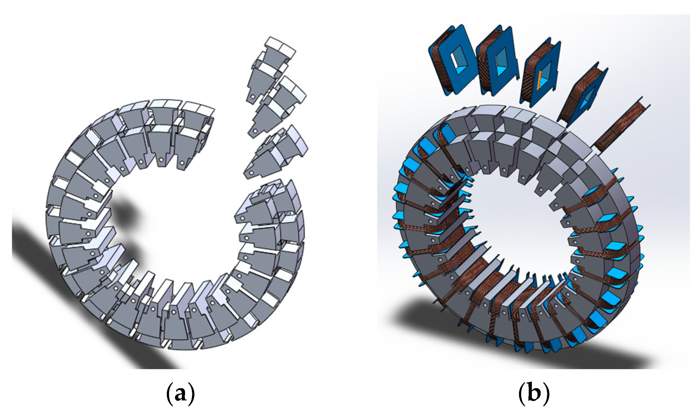
Figure 1 shows a structure diagram of the ARF-PMSM, mainly including traction wheel, rotor, SMC stator core, annular winding, and casing. It is characterized by full use of the space of the motor, combining axial flux and radial flux, so as to improve the torque density of the motor. The stator core is pressed and formed with SMC material. It is worth mentioning that it is difficult to press and form the stator core as a whole with SMC material for large shapes. Therefore, this paper proposes that the stator core be assembled with a modular stator, as shown in Figure 2a. The annular winding is wound on a specific insulation skeleton, and then assembled with a modular SMC stator as a whole, as shown in Figure 2b. The SMC stator’s iron core is sleeved on the stator support shaft and fixed to the motor housing through bolts. The SMC stator’s iron core is equipped with symmetrically arranged axial rotors along the left and right sides of the axis. The surface of the axial rotor close to the stator side is pasted with uniformly arranged axial permanent magnets. The SMC stator’s iron core is equipped with radial rotors along the outer dimension of the radial side. The surface of the radial rotor close to the stator side is pasted with uniformly arranged radial permanent magnets, as shown in Figure 3. The motor has three effective air-gap magnetic fields, achieving high torque density without increasing the overall dimensions, and improving the utilization of the stator core’s materials and motor space.
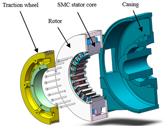
Figure 1.
Structure diagram of the ARF-PMSM.

Figure 2.
Stator core and winding of the ARF-PMSM. (a) SMC modular stator; (b) annular winding.
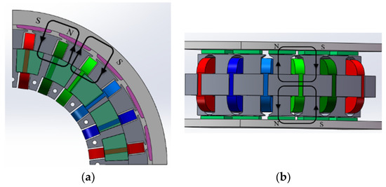
Figure 3.
Stator core and winding of the ARF-PMSM. (a) Radial-flux circuit; (b) axial-flux circuit.
The machining of the ARF-PMSM stator core is the key to the manufacturing of this type of motor. The axial superposition or winding of silicon-steel sheets can only realize the axial or radial tooth structure and cannot achieve a circular tooth structure. Therefore, this structure is suitable for processing with SMC. The SMC material is made using powder-metallurgy technology, which is composed of metal-powder particles with surface insulation. It can be pressed into parts with complex shapes at the same time, and it has good isotropic magnetic properties. It is very suitable as the core material of axial and radial flux motors. However, compared with silicon-steel sheets, it also has the disadvantages of low permeability, large hysteresis loss, and low mechanical strength. Direct replacement the traditional silicon-steel sheet with SMC material in the application field would not achieve good results. When using it for motor design and manufacturing, it is necessary to fully consider the material characteristics, give full play to its advantageous isotropic magnetic properties, and study the magnetic properties of materials under three-dimensional magnetic-field excitation.
The ARF-PMSM can be seen as making full use of the end space of the motor on the basis of the ordinary radial motor. The axial magnetized permanent magnet is placed on the end plate. The permanent magnet interacts with the annular winding to improve the torque density and material utilization (especially copper) of the motor. In addition, its potential advantages include the following:
- (1)
- The air-gap area of the axial and radial motors is larger. When the outer diameter of the motor is the same, the effective air-gap area must be larger than that of the ordinary radial motor.
- (2)
- The motor-winding-end length does not increase with the motor diameter, so the motor’s torque density can be improved by increasing the ratio of diameter to length.
2.2. Magnetic-Circuit Characteristics and Working Principle of the ARF-PMSM
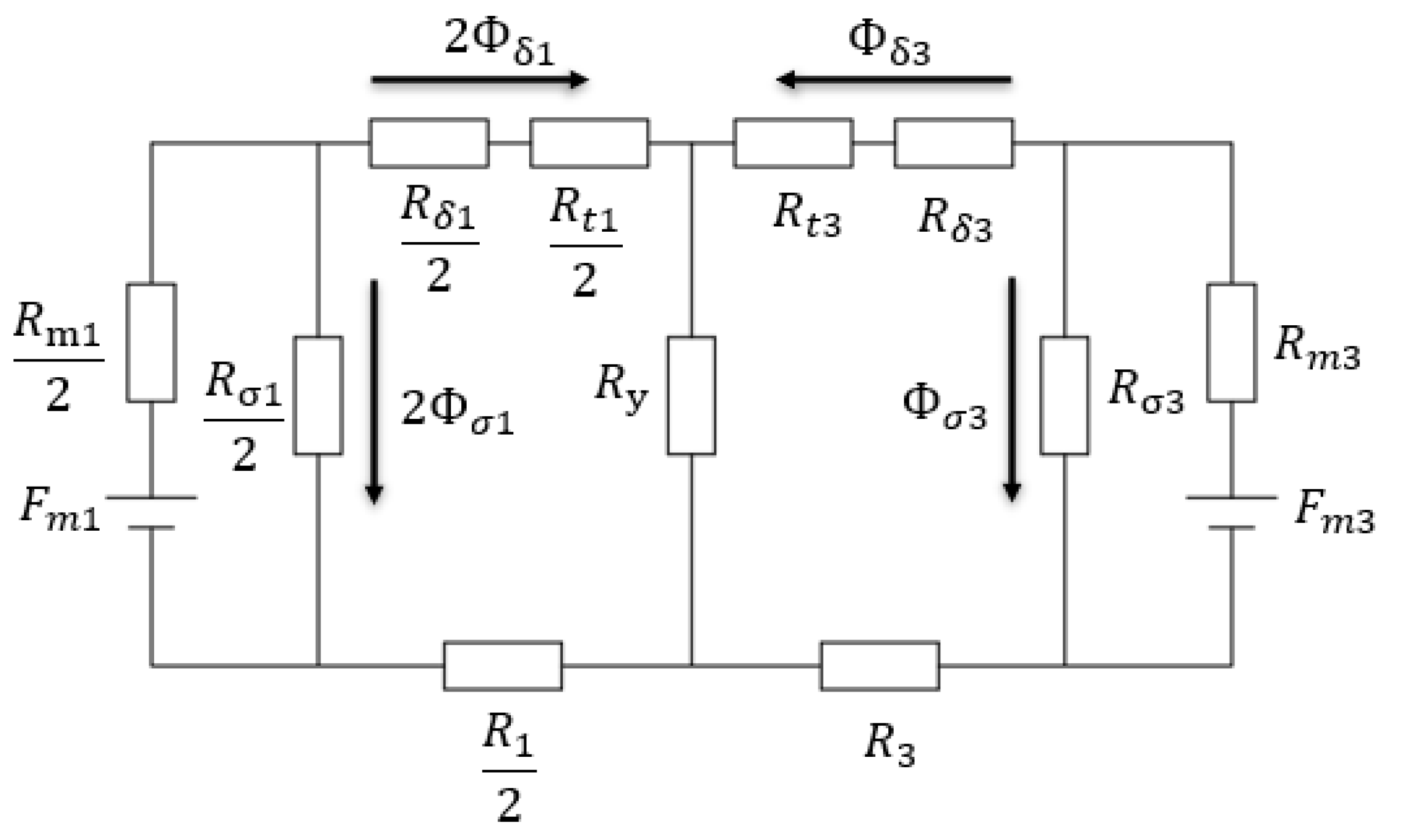
We analyzed the magnetic-circuit characteristics of the ARF-PMSM according to the structure shown in Figure 3. The ARF-PMSM can be regarded as a radial-flux motor and two axial-flux motors sharing the same stator core. In order to make the direction of the electromagnetic torque generated by motors on each side consistent, the two axial magnetic poles in the same axial section should have the same polarity as the radial magnetic poles. Therefore, when drawing the equivalent magnetic-circuit diagram of the electric machine, it can be considered that the magnetic circuit is composed of a radial magnetic circuit and two axial magnetic circuits in parallel, as shown in Figure 4.
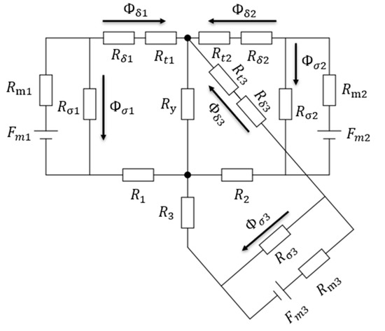
Figure 4.
No-load equivalent magnetic circuit of the ARF-PMSM.
According to the diagram of the no-load equivalent magnetic circuit in Figure 4, the following loop equations can be listed by using the magnetic-network method:
where
where Fm1 and Fm2 are the equivalent magnetomotive forces of each pair of magnetic poles of the left and right axial permanent magnets, respectively; Fm3 is the equivalent magnetomotive force of each pair of magnetic poles of the radial permanent magnet; Φδ1 and Φδ2 are the main fluxes of the axial-flux path, and Φδ3 is the main flux of the radial-flux path; Φσ1 and Φσ2 are the leakage flux of the axial-flux path, and Φσ3 is the leakage flux of the radial flux path; Rm1 and Rm2 are the equivalent internal magnetic resistances of the axial PM, and Rm3 is the equivalent internal magnetic resistance of the radial PM; Rt1 and Rt2 are the axial stator’s tooth reluctance, and Rt3 is the radial stator’s tooth reluctance; R1 and R2 are the axial rotor’s yoke reluctance, R3 is the radial rotor’s yoke reluctance, Rδ1 and Rδ2 are the leakage reluctance of the axial-flux path, and Rδ3 is the leakage reluctance of the radial-flux path; and Ry is the reluctance of the yoke of the stator core.
From the magnetic circuit structure shown in Figure 3, it can be seen that the two axial magnetic circuits are symmetrical, and the parameters are essentially the same, that is, Rm1 = Rm2, Rt1 = Rt2, Rδ1 = Rδ2, Φδ1 = Φδ2, and Φσ1 = Φσ2. Therefore, the two axial magnetic circuit circuits can be combined, and the simplified equivalent magnetic-circuit diagram is shown in Figure 5.
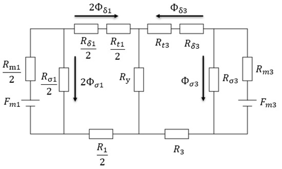
Figure 5.
Simplified equivalent magnetic circuit of the ARF-PMSM.
According to Figure 5, the loop Equation (5) can be obtained:
Next, the main magnetic flux of the axial magnetic circuit, the radial magnetic circuit, and the magnetic-flux expression of the stator yoke can be obtained, as shown in Equation (6):
According to Equation (6), the following conclusions can be drawn:
- (1)
- The axial permanent magnet and the radial permanent magnet weaken the main magnetic flux of the radial magnetic circuit and the main magnetic flux of the axial magnetic circuit, respectively. When the stator yoke is unsaturated, that is, Ry << Raa, Ry << Rac, the weakening effect is very small.
- (2)
- If only the equivalent magnetomotive force of the axial permanent magnet is considered, that is, Fm3 = 0, the magnetic flux ratio of the axial magnetic flux and the radial magnetic flux is 2Φδ1/Φδ3 = −Rac/Ry. Because the expression contains forms of magnetic resistance, such as an air gap, that is, Ry << Rac, then Φδ1 >> Φδ3, the magnetic flux passing through the radial air gap is very small, and the main magnetic flux of the axial magnetic circuit is mainly closed through the axial rotor’s core; by contrast, the main magnetic flux of the radial magnetic circuit is mainly closed through the radial rotor’s core. This shows that the magnetic flux of the axial magnetic circuit is mainly generated by the axial permanent magnet, while the magnetic flux of the radial magnetic circuit is mainly generated by the radial permanent magnet, and the coupling between the axial and radial magnetic circuits is very small.
- (3)
- The magnetic flux passed by the yoke of the stator core is the sum of the radial magnetic flux and the axial magnetic flux. Therefore, when designing the ARF-PMSM, it is necessary to consider the value of the cross-sectional area of the stator yoke to avoid the adverse impact on the axial magnetic circuit and the radial magnetic circuit due to the oversaturation of the magnetic flux of the stator yoke.
2.3. Power-Size Equation of the ARF-PMSM
The magnetic circuit of the ARF-PMSM is parallel and has no magnetic couplings; the design method adopts the equivalent magnetic-circuit method for order reduction, which divides the original structure into three-dimensional radial- and three-dimensional axial-flux parts. The electromagnetic characteristics of each component are calculated separately and compared with the integrated three-dimensional analysis results. Next, the 2D analysis method is applied to each section and the results are compared with the results of the 3D separation. When the convergence error meets the judgment criteria, it can be considered that the 2D magnetic-circuit-calculation results can be used for the 3D model.
The main dimensions of the ordinary radial-flux-structure motor refer to the diameter and length of the armature, while for the axial-flux structure’s disc motor, they refer to the average diameter and radial length of the armature. As an electromagnetic device for electromechanical energy conversion, its main dimensions are closely related to electromagnetic power. The calculated power of AC motor can be expressed as
where m is number of motor phases, E is the armature-winding-phase electromotive force, and I is the rated phase current.
The back electromotive force of stator winding can be expressed as
where KNm is the waveform coefficient of the air-gap magnetic field. When the air-gap magnetic field is sinusoidal, it is equal to 1.11, f is the motor frequency, Kdp is the winding coefficient, N is the total turns of each phase in the series, and Φ is the magnetic flux under each pole.
For ARF-PMSM, ignoring the edge effect of the air-gap magnetic field, assuming that the pole-arc coefficients of the axial permanent magnet and the radial permanent magnet are the same, the magnetic flux under each pole can be expressed as
where p is the pole pairs of the motor, Bδ1av is the average value of the air-gap flux density at an axial pole distance, Bδ3av is the average value of the air-gap flux density at a radial pole distance, S1 is the area of each pole in the axial direction (one side), S3 is the area of each pole in the radial flux, D1 is the outer diameter of the stator core, Di1 is the inner diameter of the stator core, Bδ1 is the maximum magnetic-flux density at the axial- air gap, Bδ3 is the maximum magnetic-flux density of the radial air gap, La is the axial length of the armature, and αi is the pole-arc coefficient calculated for the permanent magnet.
For ARF-PMSM, the electric loading of the motor is calculated according to the average radius position of the armature:
where Dav is the average diameter of the armature, .
According to Equations (9)–(12), the calculated power is
where λ is the ratio of the inner diameter to the outer diameter of the stator core of the ARF-PMSM, that is, .
The electromagnetic torque of the ARF-PMSM can be expressed as
According to Equation (14), the electromagnetic torque of the ARF-PMSM is not only related to the ratio of the inner diameter to the outer diameter, the cubic of the outer diameter, and the square of outer diameter, but also to the axial length of the motor.
In addition, it should be noted that because the ARF-PMSM three-sided rotor’s permanent magnet is a surface structure and belongs to a non-salient pole machine, there is no reluctance torque. When Is = iq, that is, the stator current is completely composed of torque current, the motor output torque is the maximum. Therefore, the ARF-PMSM adopts a control party with id = 0.
3. Simulation and Analysis of the ARF-PMSM Electromagnetic Field
3.1. Main Parameters of the ARF-PMSM
Based on the analysis above, an ARF-PMSM with a rated power of 3.0 kW and a rated speed of 120 r/min was designed in this study for the direct-drive motor of an elevator-traction machine. The main design parameters are summarized in Table 1. The commercial finite-element-analysis software Jmag 18.0 was used for the simulation analysis.

Table 1.
Main parameters of the ARF-PMSM.
3.2. Electromagnetic Performance of the ARF-PMSM
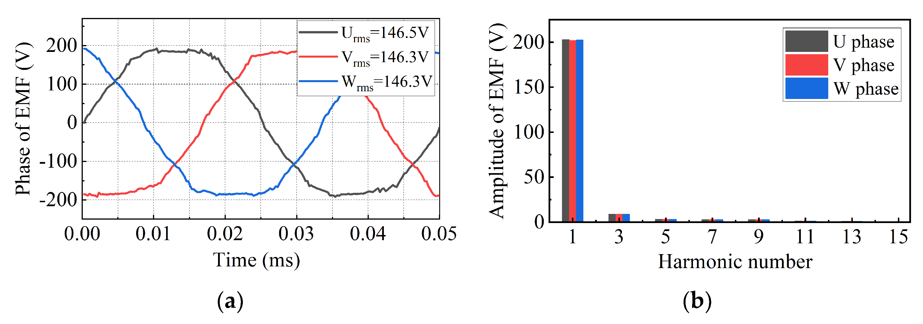
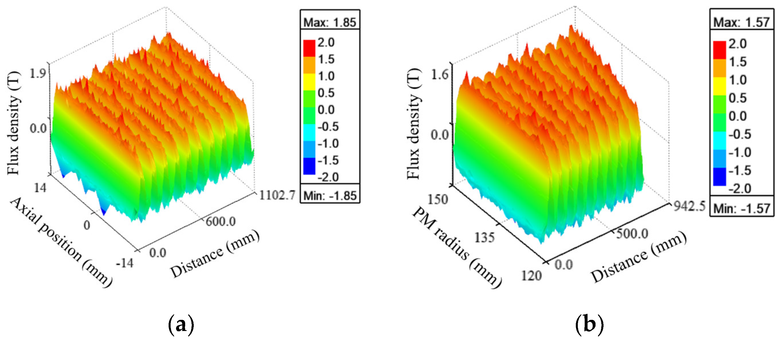
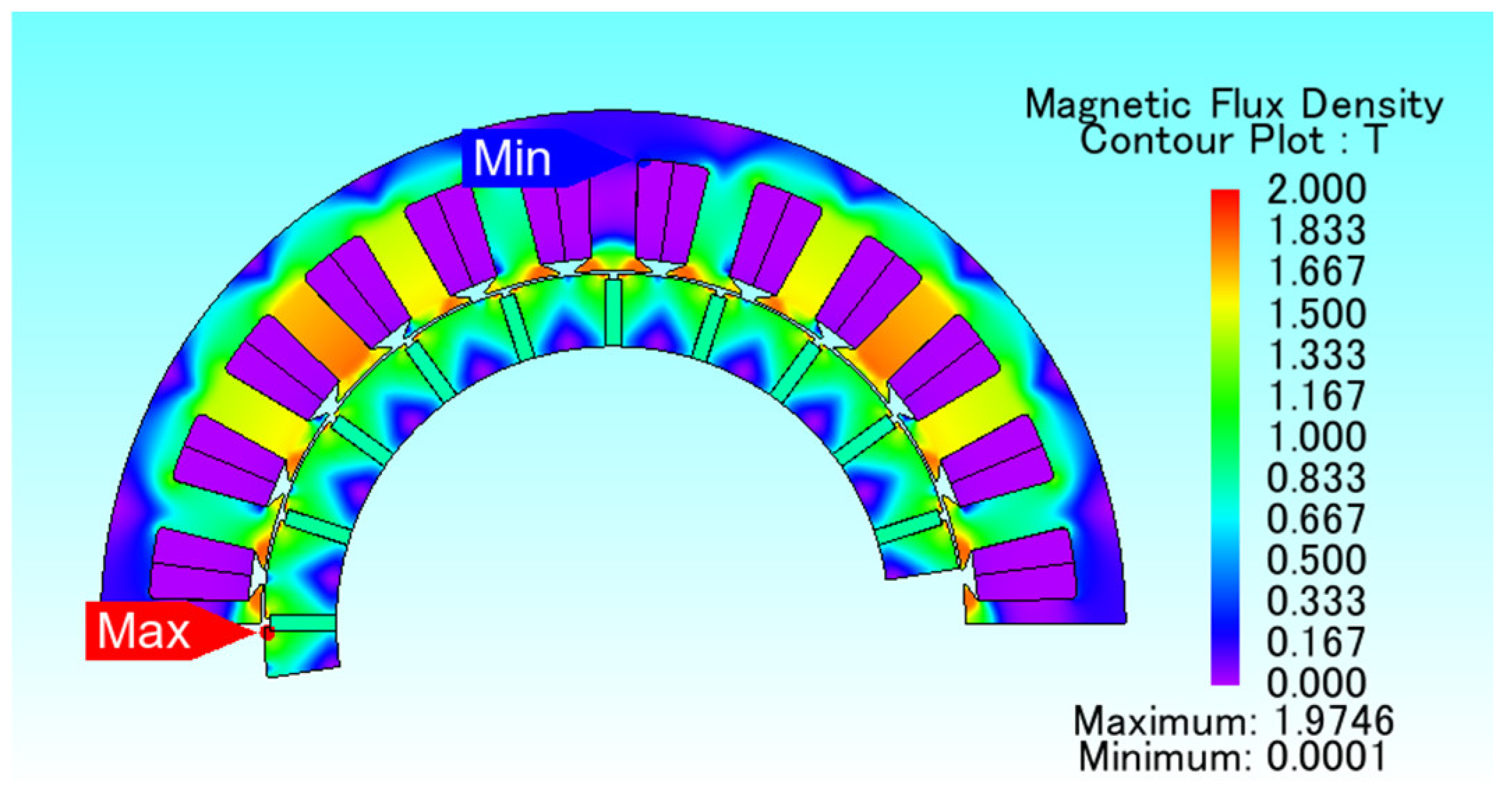
In this section, an electromagnetic-field-simulation analysis is carried out for the designed ARF-PMSM, and the results are shown in Figure 6, Figure 7, Figure 8, Figure 9, Figure 10, Figure 11 and Figure 12. It can be seen from the results in Figure 6 that the magnetic-field distribution of the ARF-PMSM is reasonable, the main magnetic circuit is not seriously saturated, and the magnetic leakage is small. The magnetic circuits of the axial flux motor and the radial flux motor form separate circuits. Figure 7 shows the no-load EMF of the ARF-PMSM. From the results, it can be seen that the waveform of the EMF is sinusoidal, the harmonic content is small, and the EMF value is in good agreement with the calculated results of the magnetic-circuit method (as shown in Table 1), which proves the accuracy and rationality of the electromagnetic design of the ARF-PMSM. Figure 8 shows the three-dimensional radial air-gap magnetic-flux density and the three-dimensional axial air-gap magnetic-flux density of the ARF-PMSM. It can be seen that the radial air-gap magnetic-flux density is uniformly distributed along the axial direction, while the axial air-gap magnetic-flux density has a trapezoidal distribution along the radial direction, which is caused by the unequal width of the outer diameter and the inner diameter of the axial PM.
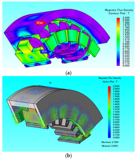
Figure 6.
No-load magnetic-field distribution of the ARF-PMSM. (a) No-load flux-density cloud diagram; (b) no-load magnetic-field vector.
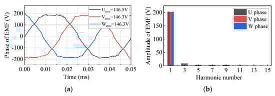
Figure 7.
No-load EMF of the ARF-PMSM. (a) Waveforms; (b) spectral.

Figure 8.
Flux density of the ARF-PMSM. (a) Radial-flux density; (b) axial-flux density.
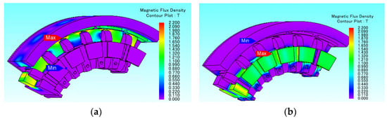
Figure 9.
Cloud map of magnetic-field distribution. (a) Independent action of radial PM; (b) independent action of axial PM.
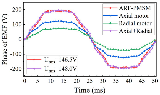
Figure 10.
Back EMF waveform.

Figure 11.
Cogging torque waveform.
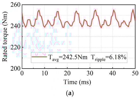
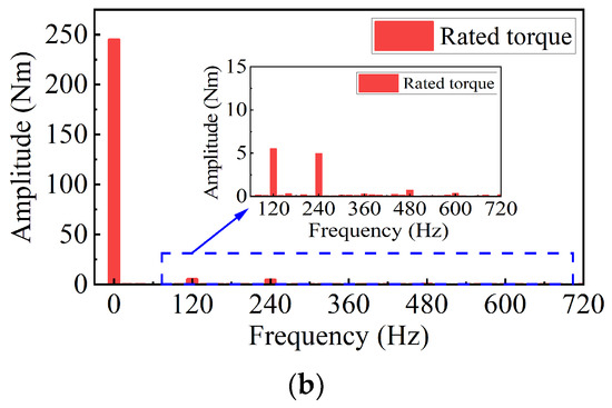
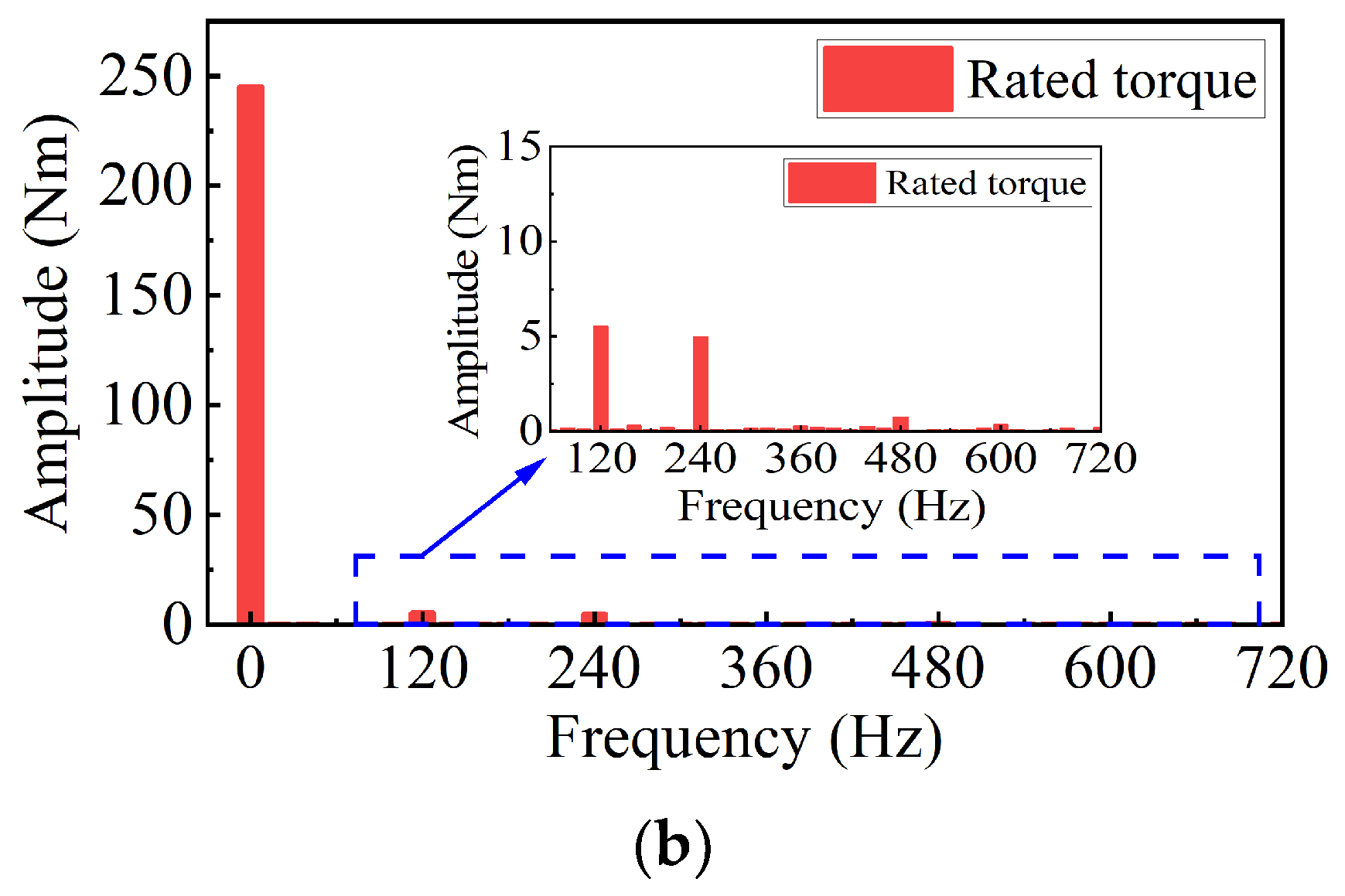
Figure 12.
Output torque of the ARF-PMSM. (a) Waveforms; (b) spectral.
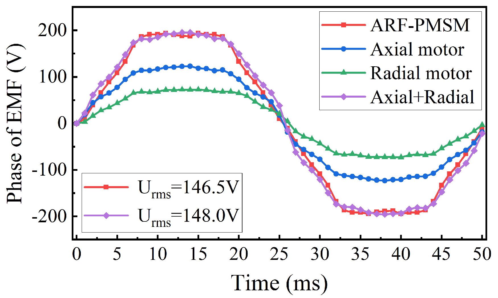
Figure 9 and Figure 10 show the magnetic-field cloud diagram and the back EMF of the ARF-PMSM when the axial PM and the radial PM acted separately. From the results, it can be seen that the superposition of the back EMF of the axial PM and the radial PM when they acted separately as generally consistent with the results from when they acted together, which also indirectly proves that the axial PM and the radial PM have very limited effects on the weakening of the main magnetic flux of the radial magnetic circuit and the main magnetic flux of the axial magnetic circuit, respectively. Furthermore, the coupling between the axial and radial magnetic circuits was very small, which was consistent with the theoretical results above.
Figure 11 shows the cogging-torque waveform of the ARF-PMSM. The peak-to-peak cogging torque was 9.19 Nm, accounting for 3.79% of the rated average torque. Figure 12 shows the ARF-PMSM’s output-torque waveform and a harmonic analysis. The torque ripple was further calculated by the following formula, which is the ratio of the peak-to-peak torque to the average torque [18]. The torque ripple of the ARF-PMSM was 6.18%, and its main components were sixth- and twelfth-ripple torques. It should be noted that the main purpose of this paper is to present the theoretical analysis, research, and design of the proposed ARF-PMSM, and compare it with other rotor-structure motors in terms of electromagnetic performance, such as torque density. Therefore, there is no further optimization design for cogging-torque and torque-ripple performance.
4. Comparison between ARF-PMSM and Two Types of Motor with Different Rotor Structures
The ARF-PMSM is compared with the traditional outer-rotor surface-mounted permanent-magnet motor and the inner-rotor spoke structure permanent-magnet motor in this section, and the electromagnetic performance of the motor is compared under the same boundary-dimension constraints. At the same time, considering the influence of the inner and outer rotor structures on the heat-dissipation capacity of the motor, the thermal-load values of the two types of outer rotor motor are consistent in the electromagnetic design, and the thermal-load value of the inner-rotor motor is higher than that of the outer-rotor motor. In addition, since the winding-end lengths of the traditional outer-rotor surface-mounted PMSM and the inner-rotor spoke-type PMSM need to be considered, assuming that the individual side lengths of the winding ends of both models are 25 mm, the effective length of the stator core is 62 mm.
The equivalent magnetic-circuit method was used to calculate the main design parameters of the compared motors, and the results are summarized in Table 2. The two-dimensional finite element method was used to simulate and analyze the outer-rotor surface-mount permanent-magnet motor and the inner-rotor spoke structure permanent-magnet motor to ensure the correctness and accuracy of the magnetic-circuit method’s calculation data. The simulation model is shown in Figure 13 and Figure 14.
Table 2.
Main parameters of the three motors.
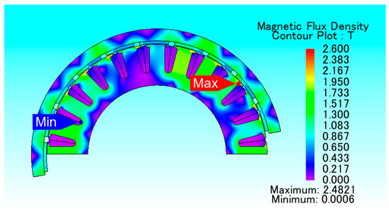
Figure 13.
Outer-rotor surface-mounted-structure motor.
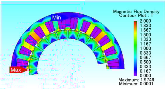
Figure 14.
Motor with inner-rotor spoke-type structure.
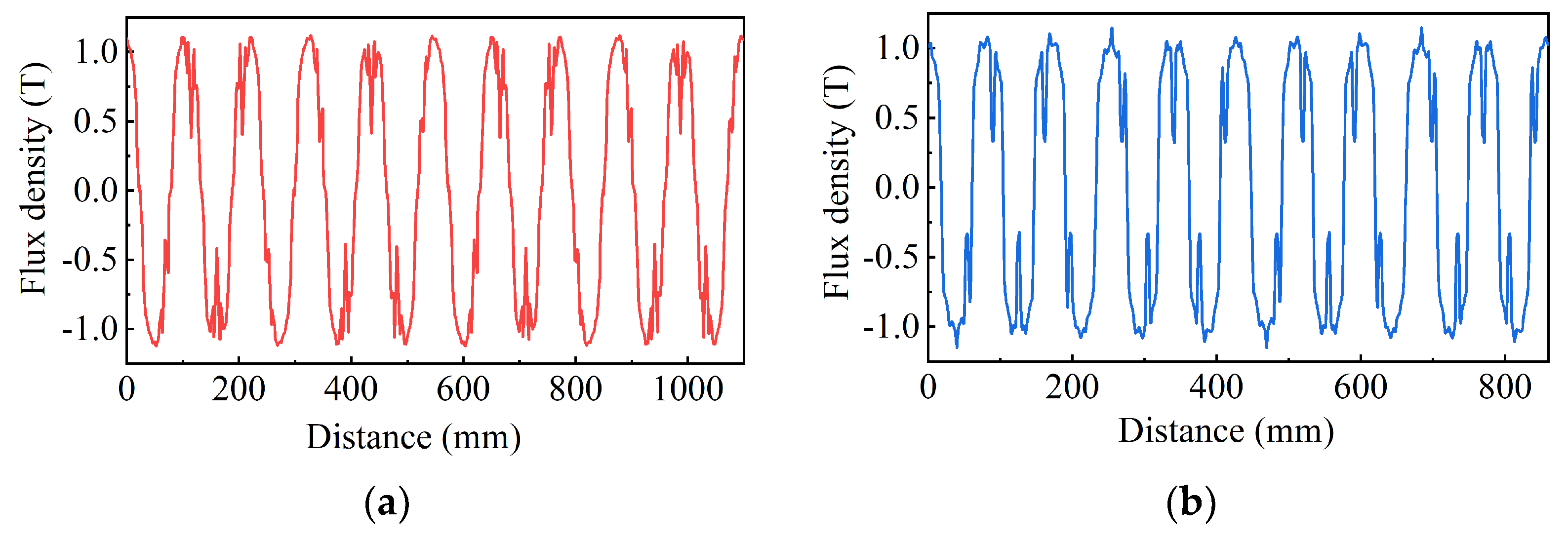
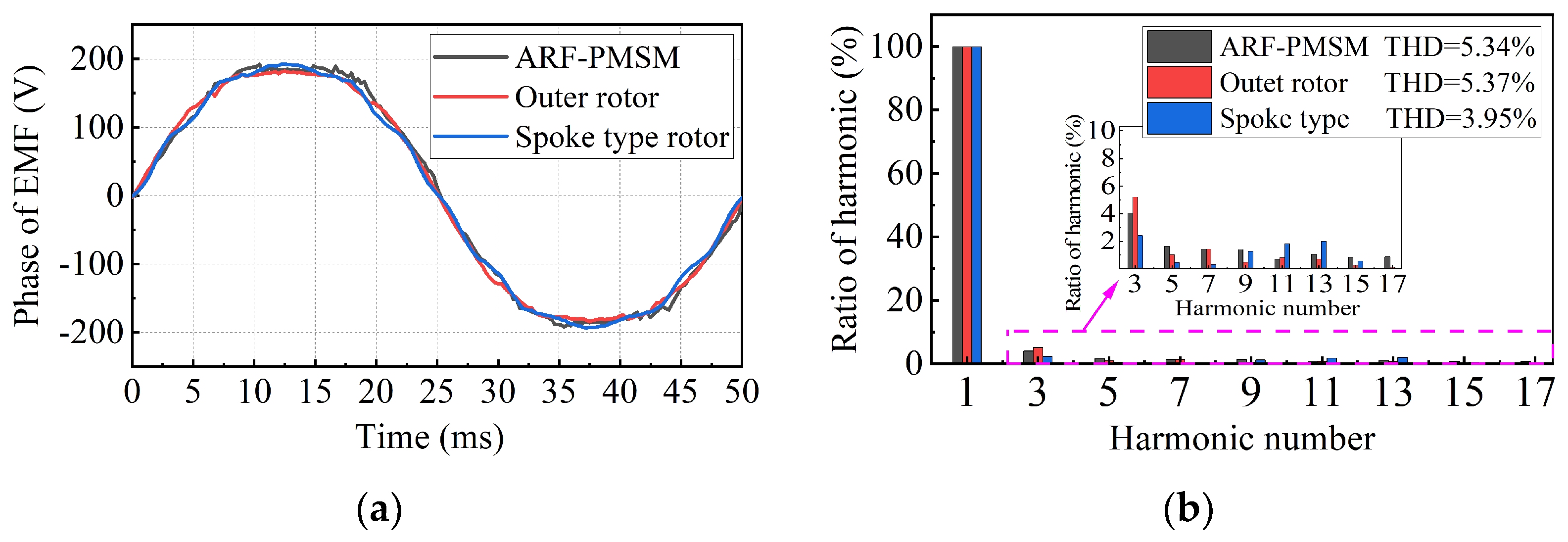
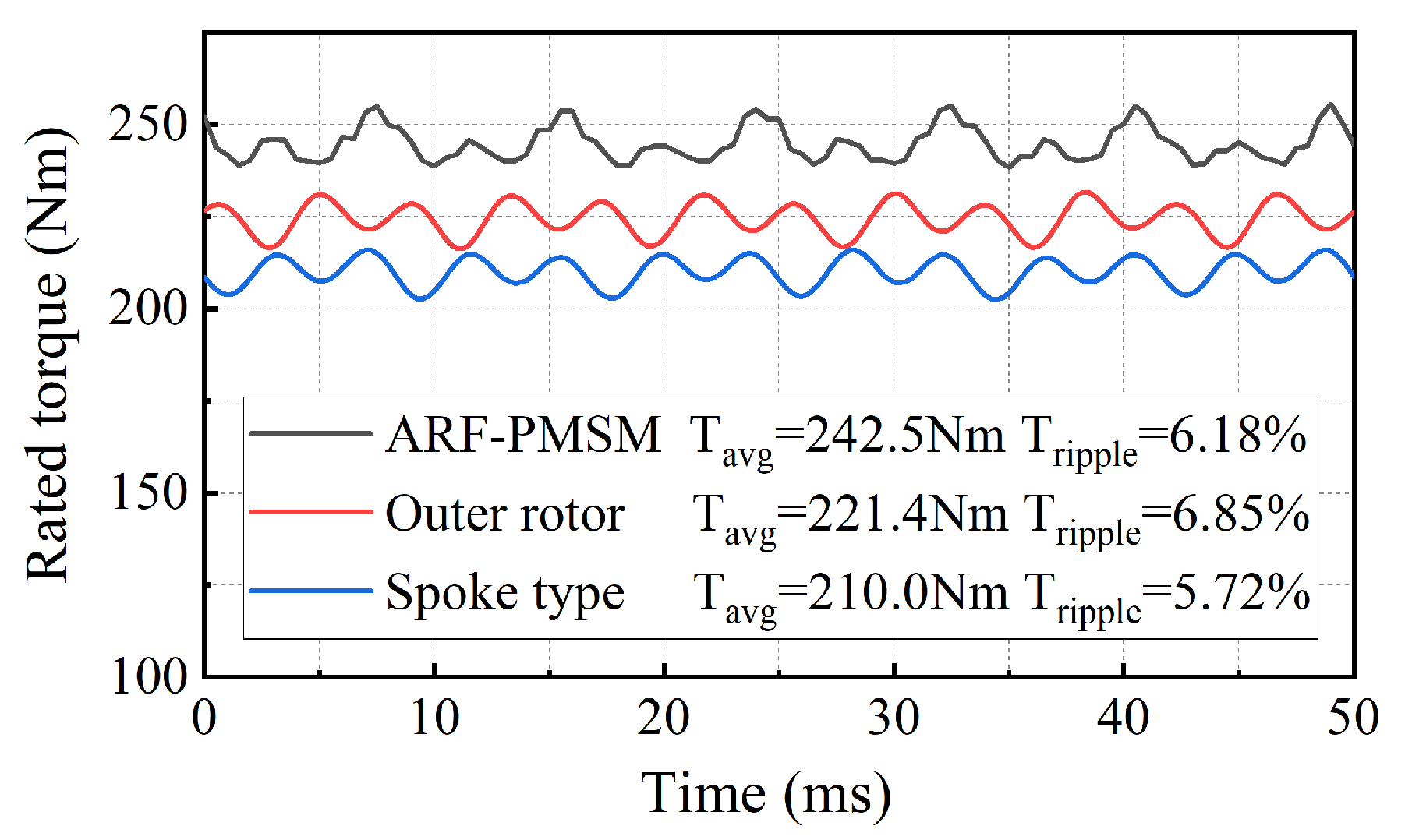
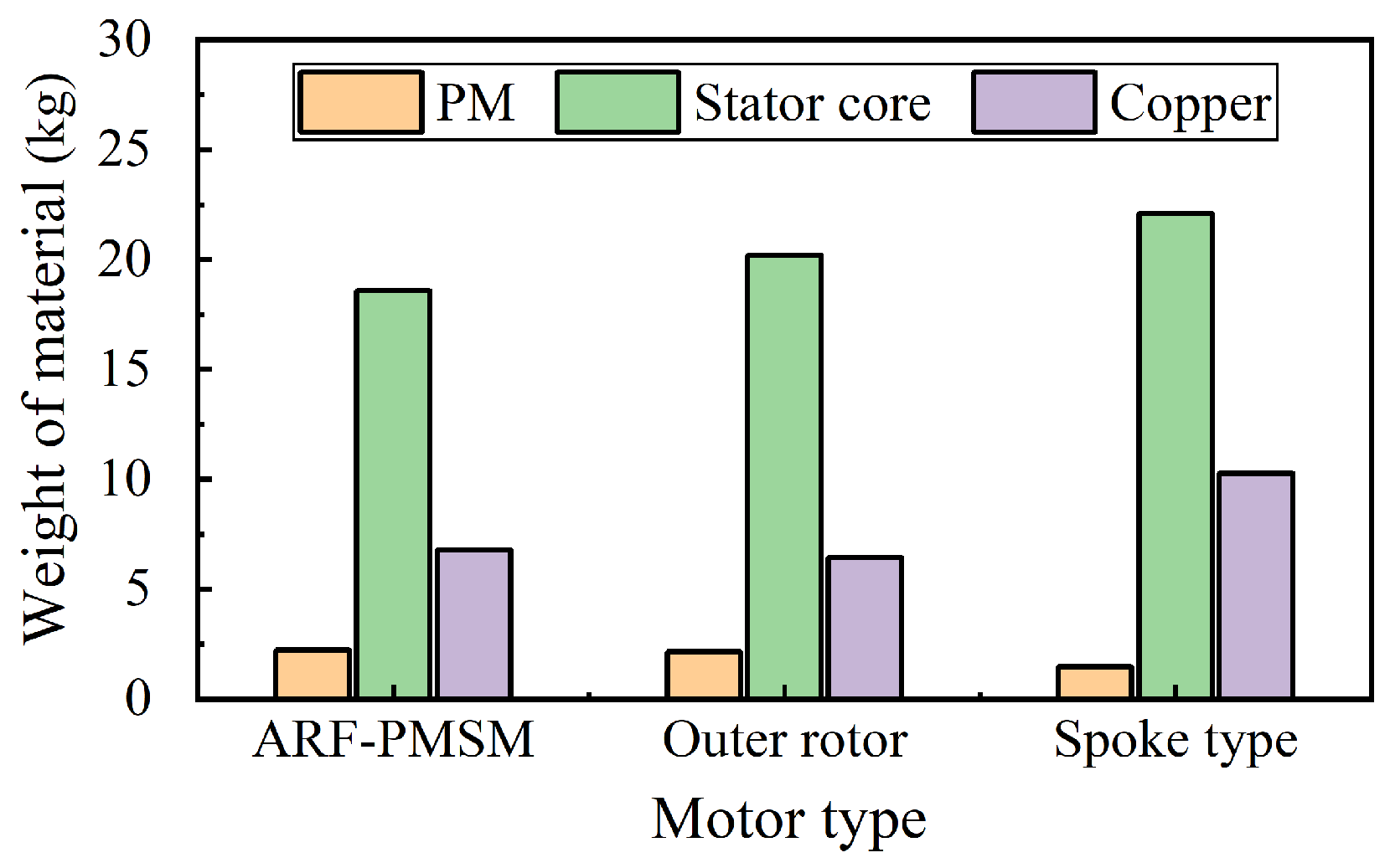
Figure 15 shows the no-load radial air-gap flux-density waveform of the outer-rotor surface-mounted PMSM and the inner-rotor spoke-type PMSM. Figure 16 shows three types of back EMF waveform and a harmonic analysis. Figure 17 shows the rated output torque of the three motors. Figure 18 compares the electromagnetic-material consumption of different types of motor.
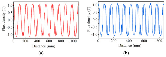
Figure 15.
Radial air-gap flux density. (a) Outer rotor; (b) spoke-type rotor.
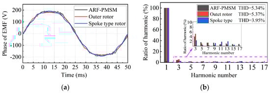
Figure 16.
Comparison of no-load EMFs. (a) Waveforms; (b) spectral.
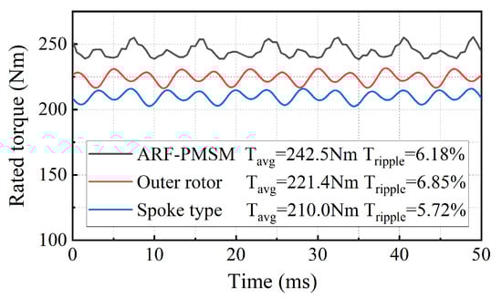
Figure 17.
Rated output torque.
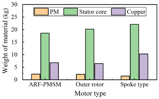
Figure 18.
Electromagnetic-material consumption of different types of motor.
The comparative-analysis results above show that under the same boundary-dimension constraints, the ARF-PMSM has a higher torque density. Compared with the traditional outer-rotor PMSM and the inner-rotor spoke-type PMSM, its torque density is higher by 10.86% and 16.88%, respectively. The torque density of the motor with the new topology is significantly improved. On some special occasions, such as when the installation space of the traction machine in the elevator room is very limited, the use of a general motor that meets the size requirements cannot meet the required torque requirements, and the ARF-PMSM can effectively solve this problem. It should also be noted that the stator and rotor materials used in the three types of motor compared here are not entirely the same. Therefore, the definition of the optimal criterion of torque density in this article is the torque value per unit of volume. Among the three types of motor, the torque ripple of the motor with the spoke-type is better than those of the other two types, mainly because it has a lower THD value of no-load back EMF.
In addition, it can be seen from the comparison results in Figure 18 that in terms of the amount of stator-core materials, the ARF-PMSM is the smallest, followed by the outer-rotor PMSM, and the spoke-type PMSM is the largest. Regarding copper consumption, the ARF-PMSM and outer-rotor PMSM are both low, while the spoke-type PMSM is about 30% higher. This is because the air-gap diameter of the inner-rotor spoke-type PMSM is smaller than that of the ARF-PMSM and the outer-rotor PMSM, and the magnetic flux per pole is lower. Therefore, the number of winding turns (copper weight) needs to be increased to meet the electrical-performance requirements. In addition, we also found that the permanent magnet’s usage of the spoke-type PMSM is extremely low, at only 67.7% of the outer-rotor PMSM. This is because the magnetic circuit of the permanent magnet of the spoke-type rotor structure is tangential, which has a good magnetic gathering effect [19]. In general, the ARF-PMSM proposed in this paper has a high torque density, and its consumption of permanent magnets, copper wire, and stator-core materials is at a low level. Although the SMC materials are expensive at present, ARF-PMSM still has strong competitiveness in some special applications, and with the rapid development of materials, the motor with the proposed structure will offer huge potential advantages in the future.
5. Conclusions
This paper presents a high-torque-density ARF-PMSM, which is used to drive an elevator-traction motor. In this paper, the overall mechanical structure of the ARF-PMSM was presented and the modular manufacturing idea of combining an SMC material’s stator core with annular winding was proposed to facilitate the manufacturing of the proposed motor structure. The characteristics of the ARF-PMSM’s magnetic circuit structure were analyzed by using the equivalent magnetic-circuit method, the magnetic coupling between the axial and radial magnetic flux was studied, and the power dimension equation was derived. The results show that the flux of the axial magnetic circuit was mainly generated by the axial PM, and the flux of the radial magnetic circuit was mainly generated by the radial PM. When the stator yoke was not saturated, the coupling between the axial and radial magnetic circuits was very small. The flux passing through the yoke of the stator core was the sum of the radial flux and the axial flux. Therefore, the cross-sectional area of the stator yoke should be considered in the design of the ARF-PMSM to avoid the adverse influence of the supersaturation of the stator-yoke flux on the axial magnetic circuit and the radial magnetic circuit. Finally, the electromagnetic performance and electromagnetic-material consumption of the ARF-PMSM were compared with the outer-rotor PMSM and the inner-rotor spoke-type PMSM using the finite element method. The research results show that the proposed motor has the advantage of high torque density, and that the consumption of the permanent magnet, copper wire, and stator-core material is at a low level. The research content of this paper provides a new design idea in the form of a high-torque-density PMSM for use in elevator-traction machines.
Author Contributions
J.Z. wrote the paper and analyzed the data; J.L. supervised all processes; H.W. checked the paper format. All authors have read and agreed to the published version of the manuscript.
Funding
This research received no external funding.
Data Availability Statement
Not applicable.
Conflicts of Interest
The authors declare no conflict of interest.
References
- El-Refaie, A.M. Fractional-slot concentrated-windings synchronous permanent magnet machines: Opportunities and challenges. IEEE Trans. Ind. Electron. 2010, 51, 107–121. [Google Scholar] [CrossRef]
- Kim, B.; Lipo, T.A. Design of a Surface PM Vernier Motor for a Practical Variable Speed Application. In Proceedings of the IEEE Energy Conversion Congress and Exposition (ECCE), Montreal, QC, Canada, 20–24 September 2015; pp. 776–783. [Google Scholar]
- Reddy, P.B.; EL-Refaie, A.M.; Huh, K. Effect of Number of Layers on Performance of Fractional-Slot Concentrated-Windings Interior Permanent Magnet Machines. IEEE Trans. Electron. 2014, 30, 2205–2218. [Google Scholar]
- Zhu, L.; Jiang, S.Z.; Zhu, Z.Q.; Chan, C.C. Analytical Methods for Minimizing Cogging Torque in Permanent-Magnet Machines. IEEE Trans. Magn. 2009, 45, 2023–2031. [Google Scholar] [CrossRef]
- Li, Y.; Xing, J.; Wang, T.; Lu, Y. Programmable Design of Magnet Shape for Permanent-Magnet Synchronous Motors with Sinusoidal Back EMF Waveforms. IEEE Trans. Magn. 2008, 44, 2163–2167. [Google Scholar]
- Zheng, P.; Zhao, J.; Han, J.; Wang, J.; Yao, Z.; Liu, R. Optimization of the Magnetic Pole Shape of a Permanent-Magnet Synchronous Motor. IEEE Trans. Magn. 2007, 43, 2531–2533. [Google Scholar] [CrossRef]
- Tavana, N.R.; Shoulaie, A. Analysis and Design of Magnetic Pole Shape in Linear Permanent-Magnet Machine. IEEE Trans. Magn. 2010, 46, 1000–1006. [Google Scholar] [CrossRef]
- Zhao, W. Optimal design of a novel V-type interior permanent magnetmotor with assisted barriers for the improvement of torque characteristics. IEEE Trans. Magn. 2014, 11, 1–4. [Google Scholar]
- Seo, J.M.; Ro, J.-S.; Rhyu, S.-H.; Jung, I.-S.; Jung, H.-K. Novel Hybrid Radial and Axial Flux Permanent-Magnet Machine Using Integrated Windings for High-Power Density. IEEE Trans. Magn. 2015, 51, 1–4. [Google Scholar] [CrossRef]
- Zhang, W.; Xu, Y.; Zhou, G. Research on a Novel Transverse Flux Permanent Magnet Motor with Hybrid Stator Core and Disk-Type Rotor for Industrial Robot Applications. IEEE Trans. Ind. Electron. 2021, 68, 11223–11233. [Google Scholar] [CrossRef]
- Wang, J.; Geng, W.; Li, Q.; Li, L.; Guo, J. A Novel Spoke-Type IPM Rotor with Hybrid Radial and Axial Flux Concentration for Reduction of Interpolar Leakage Flux. IEEE Trans. Magn. 2022, 58, 1–6. [Google Scholar] [CrossRef]
- Qiu, H.; Zhang, S.; Li, W.; Yang, C. Improvement of Ferromagnetic Bridge Structure of Axial–Radial Flux Type Permanent Magnet Synchronous Machine. IEEE Trans. Ind. Appl. 2020, 56, 3498–3505. [Google Scholar] [CrossRef]
- Wang, D.; Wang, X.; Jung, S.-Y. Cogging Torque Minimization and Torque Ripple Suppression in Surface-Mounted Permanent Magnet Synchronous Machines Using Different Magnet Widths. IEEE Trans. Magn. 2013, 49, 2295–2298. [Google Scholar] [CrossRef]
- Du, Z.S.; Wu, D.; Zhu, Z.Q. Design Tradeoff Between Cogging Torque and Torque Ripple in Fractional Slot Surface-Mounted Permanent Magnet Machines. IEEE Trans. Magn. 2015, 51, 1–4. [Google Scholar]
- Zhang, Z.; Yu, S.; Zhang, F.; Jin, S.; Wang, X. Electromagnetic and Structural Design of a Novel Low-Speed High-Torque Motor with Dual-Stator and PM-Reluctance Rotor. IEEE Trans. Appl. Supercond. 2020, 30, 1–5. [Google Scholar] [CrossRef]
- Zhang, J.; Zhang, B.; Feng, G.; Gan, B. Design and Analysis of a Low-Speed and High-Torque Dual-Stator Permanent Magnet Motor with Inner Enhanced Torque. IEEE Access 2020, 8, 182984–182995. [Google Scholar] [CrossRef]
- Zhao, F.; Lipo, T.A.; Kwon, B.-I. A Novel Dual-Stator Axial-Flux Spoke-Type Permanent Magnet Vernier Machine for Direct-Drive Applications. IEEE Trans. Magn. 2014, 50, 1–4. [Google Scholar] [CrossRef]
- Yang, Y.-P.; Peng, M.-T. A Surface-Mounted Permanent-Magnet Motor with Sinusoidal Pulsewidth-Modulation-Shaped Magnets. IEEE Trans. Magn. 2019, 55, 1–8. [Google Scholar] [CrossRef]
- Zhang, J.; Zhang, B.; Feng, G. Influence of Introducing the Rotor MMF Harmonic on Torque Performance of Spoke Type Permanent Magnet Motor With FSCW. IEEE Access 2020, 8, 196123–196134. [Google Scholar] [CrossRef]


Disclaimer/Publisher’s Note: The statements, opinions and data contained in all publications are solely those of the individual author(s) and contributor(s) and not of MDPI and/or the editor(s). MDPI and/or the editor(s) disclaim responsibility for any injury to people or property resulting from any ideas, methods, instructions or products referred to in the content. |
© 2023 by the authors. Licensee MDPI, Basel, Switzerland. This article is an open access article distributed under the terms and conditions of the Creative Commons Attribution (CC BY) license (https://creativecommons.org/licenses/by/4.0/).