Abstract
Compared to traditional power grids, microgrids have a more flexible operating mode. There are various distributed power sources within the microgrid, and different types of distributed power sources have different control methods. Once a short-circuit fault occurs in the microgrid, these characteristics will increase the difficulty of microgrid fault diagnosis and reduce the accuracy of microgrid fault diagnosis. This paper proposes an error-correcting particle swarm optimization back propagation microgrid fault diagnosis method for the diagnosis of short-circuit faults in microgrids that identifies the accuracy of alarm signals, corrects unreasonable signals, and obtains the correct fault set of the microgrid through the temporal logic relationship between each protection. Using the particle swarm optimization back propagation (PSO-BP) neural network algorithm to train fault alarm signals, fast convergence can be achieved, and accurate diagnostic results can be obtained after the sixth generation training is completed. As this fault diagnosis algorithm is applied to line protection equipment, it can be used to diagnose all types of short-circuit faults. This algorithm is easy to implement and has a small data scale, which is conducive to efficient and concise fault diagnoses in microgrids.
1. Introduction
A microgrid is a novel grid system with distributed power sources combined with customer loads, a new system that provides the necessary electrical and thermal energy [1]. Microgrids are controlled by and have their energy converted through power electronics [2]. Microgrids contain generators, loads, energy storage devices, and control devices and are highly integrated and controllable systems [3]. The energy of a microgrid mainly comes from renewable resources, such as wind, light, and tidal energy, which is converted by micro gas turbines, internal combustion engines, fuel cells, solar cells, wind turbines, etc., to provide electricity and heat for production and living [4,5]. Microgrids directly benefit customers, reduce line construction investment, and are more economical and reliable with regard to power supply [6]. There are two modes of operation for microgrids: grid connection and islanding, and there are multiple distributed power sources inside the microgrid. If a short-circuit fault occurs in the microgrid, the diverse operating modes and distributed power control methods make fault diagnosis more difficult [7,8,9]. When the external distribution network fails, the microgrid can switch to islanding mode and self-power through distributed power sources, flexibly and efficiently applying distributed generation technology to ensure the quality of the power supply [10]. Since distributed power sources are mostly clean energy and close to the load side, microgrid systems are more low-carbon, environmentally friendly, safe, and reliable [11].
Up to now, microgrid fault diagnosis is mainly for internal single or multiple device fault diagnosis [12]. The Petri net-based fault diagnosis method is more complicated due to the difficulty of modeling and is not applicable to the flexible operation mode and variable structural characteristics of microgrids [13]. However, this method can establish a microgrid fault diagnosis framework using digital twin technology, train the neural network on a cloud server, and achieve offline fault diagnosis through terminal devices, with a diagnostic accuracy of 95% [14]. However, the method based on cloud big data analysis requires higher equipment. There are also some fault diagnosis methods for power systems that provide a basis for microgrid fault diagnosis with high accuracy [15,16,17]. By studying the impact of different sizes of inductors on currents, a scheme for fault detection and location can be implemented by using di/dt to limit the voltage change rate measured on the line side of the reactor, which can effectively protect the high-voltage DC power grid [18]. The threshold-based fault diagnosis method is simple and easy to implement, but improper selection of threshold value will lead to false alarm and leakage, which is greatly affected by system components and operation mode [19]. Fault diagnosis methods based on state estimation are often used in microgrids where state parameters are not directly available [20]. Back propagation-based fault diagnosis methods are limited by the completeness of the training set and cannot restore the fault evolution process [21]. The support vector machine-based fault diagnosis method has high accuracy for fault classification and is suitable for highly structured microgrids [22]. Spiking neural P systems with self-updating rules (srSNPS) method effectively unifies the attribute reduction ability of rough sets and the apoptosis mechanism of biological neurons in the P system. This algorithm utilizes the apoptosis algorithm of conditional neurons to remove redundant information from fault messages, objectively handling the uncertainty and incompleteness of fault information without using historical statistical data and professional knowledge [23]. The fuzzy reasoning spiking neural P systems (FDSNP) algorithm uses a fuzzy inference spike neural P system with trapezoidal fuzzy numbers to model and determine the fault location, which has good fault tolerance [24]. A fault diagnosis method for photovoltaic power generation systems based on artificial neural networks, which can identify eight fault states, provides a solution for fault diagnosis of distributed power sources in microgrids [25]. At present, fault diagnoses regarding microgrids mostly involve the adoption of traditional grid diagnostic methods that do not effectively process the fault signals generated by microgrid systems, resulting in low accuracy of the dataset and difficulty in training intelligent algorithms [26,27,28]. Moreover, the size of microgrids is small, and faults often occur on the user side, requiring faster and more accurate diagnostic methods. The fault diagnosis method for microgrids should be as simple and fast as possible, in line with the structural and operational characteristics of microgrids.
The PSO-BP algorithm has high computational accuracy, fast convergence, and does not require the optimization function to be differentiable and continuous. The algorithm has a simple structure and is easy to program and implement. Based on the back propagation neural network of particle swarm optimization hybrid drosophila algorithm (PSO FOA-BP), PSO FOA effectively solves the weight and deviation problems of back propagation neural network (BPNN) [29]. Through deep learning and predictive ability, the heuristic PSO-BP algorithm can achieve a fault diagnosis accuracy of 95% [30]. The integration of big data analysis and BP neural network can achieve an accuracy rate of 96.8% for microgrid fault diagnosis [31]. By combining wavelet transform with BP neural network, the initial fault angle and transition resistance can be ignored, achieving high-precision microgrid fault diagnosis [32]. The training set is crucial for PSO-BP neural networks, and complex and redundant training sets are not conducive to the convergence of calculation results as they increase diagnosis time.
At present, there have been rich achievements in fault diagnosis for traditional power grids, but there is little research on fast and accurate fault diagnosis methods for microgrids [33]. This paper focuses on line protection equipment, combines the correction of the temporal relationship of fault alarm signals with the PSO-BP algorithm, and trains neural networks using accurate and complete fault sets to quickly obtain accurate fault diagnosis results. The main research aims of this article are as follows:
1. To determine whether the fault alarm signal is generated within the specified time by utilizing the temporal logic relationship of the fault alarm signal. To quickly determine the action information of the main and backup protection and corresponding circuit breakers and eliminate the information of circuit breaker misoperation and rejection.
2. To combine the PSO-BP algorithm and train the neural network using an accurate and complete fault set to achieve fast convergence. The PSO-BP algorithm in this article can converge in the sixth generation and accurately judge the fault alarm signal to obtain the location of the fault line.
Section 2 of this paper contains research on the characteristics of the microgrid short-circuit fault and temporal logic relationship of the line protection equipment. In Section 3, we use the PSO-BP algorithm to carry out joint fault diagnosis and use the corrected alarm information set for training. In Section 4, we use the alarm signal generated by a microgrid model to carry out fault diagnosis and verify the accuracy of the algorithm. The full names of some abbreviations in the paper are shown in Table 1.

Table 1.
Explanation of abbreviations and notations.
2. Research on Short-Circuit Fault Alarm Signal of Microgrids
The short-circuit fault alarm signal of the microgrid contains a variety of information about the fault, which can determine the fault line and equipment through the action of the circuit breaker. Therefore, accurate and reliable fault alarm signals are of great significance for fault diagnosis. By utilizing the temporal logic relationship of line protection equipment to sort out fault alarm signals, a low dimensional fault signal training set can be established, which is beneficial for subsequent PSO-BP neural network training and prediction, improving the accuracy and speed of fault diagnosis.
2.1. Microgrid Short-Circuit Fault Characteristics
Microgrids adjust the control mode according to the characteristics of distributed power supply and the operation status of microgrid at any time; a different operation status will affect the size of microgrid fault current output value [33,34]. The sources of short-circuit fault currents are as follows: distribution network injection current, microgrid internal distributed power injection current, and microgrid internal load injection current (Inductive electric type load) [35]. The short-circuit current value is 1.2–1.5 times the current rating in the islanded state and 6–10 times the current rating in the grid-connected state. At present, microgrid fault diagnosis involves analyzing and judging two kinds of fault alarm data of switching quantities and electricity from dispatch centers at all levels, reasoning out the faulty components and faulty lines through the use of relay protection devices and corresponding protection action logic relations, and realizing fault reproduction through various algorithms to explore the cause of the fault.
For the line protection problem of different operating states in the microgrid, there is a protection method based on communication principles to solve the protection action time adjustment problem during state transition; however, because of the need to introduce external communication equipment, this method is less economical and easily affected by communication quality and signal quality. Therefore, line protection methods for microgrids not only need to be adapted to the flexible and changing characteristics of microgrids but they also need to be economical, reliable, and implementable.
For microgrids equipped with overcurrent protection, the use of low-voltage accelerated inverse time overcurrent protection can reliably protect line equipment and adapt to both microgrid islanding and grid-connected operations, reducing the need to introduce excessive amounts of additional communication equipment and reducing economic investment [36]. The use of low-voltage accelerated inverse time overcurrent protection allows for the appropriate protection action time to be rectified, enabling the logical constraints of the microgrid to establish setting criteria.
2.2. Time Constraints on Microgrids Alarm Events
The voltage and current values of the faulty line equipment will first fluctuate when the microgrid short-circuit fault occurs, followed by the main protection work and the corresponding circuit breaker tripping (or backup protection work and corresponding circuit breaker tripping). Although protection and circuit breakers have a certain logical correlation in timing, interference can cause false alarm signals due to damaged relay equipment failures, etc. Therefore, the alarm signal needs to be logically conditioned to ensure that the action of each link occurs within the specified time to exclude the overtime error rejection message, and to ensure that the signal is correct and reliable.
Definition: indicates the moment of the alarm event . denotes the point-in-time constraint at the moment of the event . denotes and interval segment constraint in which the alarms appear sequentially.
2.3. Temporal Logic Relationship of the Microgrids Line Protection Equipment
The time point constraint of the protection event can be determined based on the rectification time of this protection. Considering the relay protection equipment involved in power systems [35], if the microgrid fault line protection p passes through the low voltage acceleration inverse time limit overcurrent protection of the rectification time value of , the backup protection delay time is , the short-circuit fault occurs at moment , the point-in-time constraint for protection events can be estimated as:
The faulty line sends an alarm signal value 1, and the fault occurs at the time of . The interval segment alarm signals for equipment fault events and protection action events are . indicates main protection operation, and indicates backup protection operation. boolean value of 0 or 1 indicates protection rejection or protection normal operation, respectively. If: , the boolean value of signal of fault event is assigned 1. At this time, to determine the failure criteria, the following is used:
In this section, the simple microgrid model shown in Figure 1 is used as an example to introduce the method to build a fault diagnosis model based on an error-correcting PSO-BP method, and the line protection method is low-voltage accelerated inverse time overcurrent protection. In Figure 1, microgrid line short-circuit fault occurs at L5, where is the main protection of line L5, is near back-up protection, and is far from back-up protection. After the occurrence of a fault, the main protection should act immediately at the moment, when the corresponding circuit breaker K7 trips at the moment . If the main protection rejects, the near backup protection operates at the moment and the circuit breaker K5 operates at the moment trips. If the near backup protection rejects again, the far backup protection operates at the moment and the circuit breaker K3 operates at the moment of tripping.
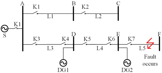
Figure 1.
Simple microgrid system model.
L5 line fault, the action relationship between the main protection and backup protection and the temporal logic are shown in Figure 2. and is the microgrid backup protection delay, which determine whether the higher-level protection is operating. Each protection action needs to satisfy the timing constraints of Equation (1) and satisfy Equation (2) to achieve a reliable and effective line alarm signal.
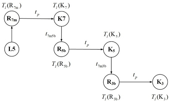
Figure 2.
The event correlation of each node in a simple micro grid system (L5 fault).
After a certain period of use and accumulation, the microgrid system will form a fault collection, and this fault information will be of great practical value in the future fault diagnosis process. After forming a more complete set of fault information, the PSO-BP method can be used for data prediction and processing, eliminating the need for step-by-step temporal consistency analysis and logical judgment. This reduces the intensity and complexity of the work and, to some extent, reduces the economic cost, making the microgrid operation more economical.
3. Basic Principles of Error-Correcting PSO-BP Fault Diagnosis
The adaptive PSO-BP is a combination of particle swarm optimization (PSO) and back propagation (BP), which first uses the PSO method to optimize each parameter of the neural network so that the artificial neural network can jump out of the local group optimization trap. The data is then predicted using the BP method to improve accuracy and speed. Constructing the sample: constructing the training matrix using the first n data in the dataset. The training sample data in this paper is 15 rows and 11 columns.
To facilitate calculations and reduce data volume, the raw data are normalized and converted to values between [0, 1]:
where the initial value and is the optimal arithmetic factor (optimized by the PSO algorithm). The initial values are all 0.5, after which they all change adaptively, which helps to improve the convergence speed of the algorithm. The traditional algorithms and both take fixed values according to experience, which has an impact on the prediction accuracy of the final neural network algorithm and makes the computing speed of the neural network algorithm decrease.
Determine the number of nodes in the hidden layer and create the neural network model: M is the number of nodes in the input layer.
The values of each parameter of the PSO algorithm [37]: the maximum number of iterations is chosen as 500, the minimum allowable error is chosen as 0.1, the particle flight amplitudes are [–5, 5] and [–2, 2], the inertia factor is 0.9, the acceleration constants are all taken as 2, the particle size is 100, and the number of neurons is 14.
Inputs to each node of the hidden layer and output layer of the neural network:
where is the input value of node j, is the input value of the input layer corresponding to node i, and is the output value of node j.
The fitness function is as follows:
Shrinkage rate is:
V(t) is the evolutionary speed of the previous. The initial value is a random number. and are learning factors, where the value 2 is taken. and are random numbers between [0, 1]. is the individual extremum of the particle. is the global threshold for the particle; is the particle position.
Particle position update:
Set the error accuracy of the iteration, return to step 7, and keep updating the position of the particles until the error accuracy is reached.
The global optimum of particle x is used as a BP network parameter to predict when the next failure will occur; the obtained prediction is inverse transformed:
After a short-circuit fault occurs in the microgrid, the system will issue an alarm signal. The alarm signal contains protective action information, which may be incorrectly conveyed due to equipment failures. Correct the alarm signal through temporal logic and then send the accurate alarm signal to the trained PSO-BP neural network, outputting the Boolean signal of the fault occurrence location to determine the fault protection information and fault line location. The entire fault diagnosis process is shown in Figure 3.
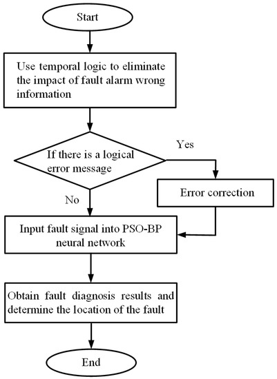
Figure 3.
Microgrid fault diagnosis process of error-correcting PSO-BP algorithm.
4. Example Analysis
In this section, a microgrid with a system bus voltage of 0.4 kV and a neutral grounding operation mode is tested as an example. DG1 is a wind turbine with a maximum output of 18 kW, DG2 is a photovoltaic cell with a maximum output of 50 kW, and DG3 is a micro gas turbine with a constant power output and a rated power of 65 kW. The current output value of all distributed power supplies does not exceed 1.5 times the rated value; the S capacity of the distribution system is 5MVA. The current output value of all distributed power supplies does not exceed 1.5 times the rated value; the S capacity of the distribution system is 5MVA. The line parameter is .
The lengths are all 800 m. The system is connected to seven loads with powers of 30 kW, 20 kW, 20 kW, 5 kW, 65 kW, 10 kW, and 10 kW, respectively. A simple microgrid structure is shown in Figure 4.
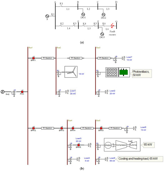
Figure 4.
Microgrid fault diagnosis model: (a) Microgrid network structure. (b) Microgrid simulation model.
Switch K1 opens to exit the distribution system S, and the microgrid is converted into an islanded state; when the switch is closed, the microgrid is in grid-connected operation. This paper assumes that a short-circuit fault occurs at the exit end of line L6, and the main (backup) protection sends trip signals to circuit breakers K6, K4, and K2 and determines the protection action time and circuit breaker tripping moment according to different fault types.
When the microgrid is in a grid-connected state, a three-phase short-circuit fault occurs at the exit of line L6, according to the low voltage acceleration inverse time limit overcurrent protection rectification principle to obtain the circuit breaker action rectification time, as shown in Table 2.

Table 2.
Circuit L5 correlation breaker action setting time.
The adaptive optimization of BP neural network parameters via the particle swarm optimization algorithm speeds up the BP neural network’s learning and enhances generalization ability. The structure of a neural network directly determines the strength of its inference ability. Broadly speaking, neural network training includes optimizing the structure and removing dull and useless neurons and connection weights, and the PSO-BP algorithm can remove redundant connections while training the network connection values.
The first 15 sets of data in the table were selected for training, and the last 2 sets were used for prediction and validation. The specific parameters were set as follows. We hope that this paper can be used as a basis to generate PSO-BP samples for microgrid devices. The training samples are shown in Table 3.

Table 3.
Adaptive PSO-BP neural network training samples.
In this paper, the adaptive PSO-BP training set is obtained by counting the historical data of the occurrence of line faults, as shown in Table 3, and then the data are predicted. The PSO-BP neural network is trained with the training set, and the 16th and 17th values are predicted using the first 15 rows of training values, which are used to verify the diagnostic accuracy for faults that have occurred. The particle swarm algorithm plays the role of weight update as well as result error judgment in the neural network learning process to avoid premature convergence.
By training the data in Table 3, the algorithm can be obtained with high accuracy (some of the training results are shown in Table 4). A quick response to fault alarms is essential for the accurate judgment of faulty lines.

Table 4.
Adaptive PSO-BP neural network prediction results.
Continue to set up new AB-side faults on the L6 line, single-side faults on the A-side, and single-side faults on the B-side to verify the accuracy of fault diagnosis for non-fault events. The values of horizontal coordinates 1–11 in Figure 4 represent A1–B0 in Table 1. The PSO-BP neural network diagnosis results match with the actual fault, which can accurately locate the fault location and judge the protection action.
Train and predict the PSO-BP neural network by setting different fault alarm signal values and fault equipment signals. The training results can be seen in Figure 5.
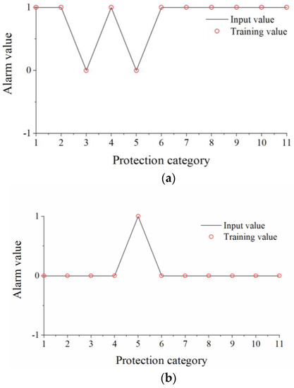
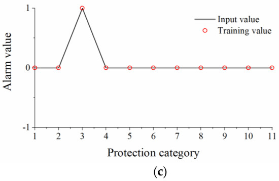
Figure 5.
Adaptive PSO-BP neural network prediction fitting curves: (a) AB-side fault prediction fitting. (b) A-side fault prediction fitting. (c) B-side fault prediction fitting.
The results show that the adaptive PSO-BP algorithm has good applicability for fault diagnosis and can accurately predict fault outcomes. The algorithm has the advantages of fast convergence, low computational time consumption, good linear fit, and certain fault tolerance, and the results of micro-network fault diagnosis can be effectively verified. By correcting the alarm signal training set, the PSO-BP algorithm quickly converges and meets the error requirements in the sixth generation, obtaining accurate diagnostic results. The convergence process is shown in Figure 6.
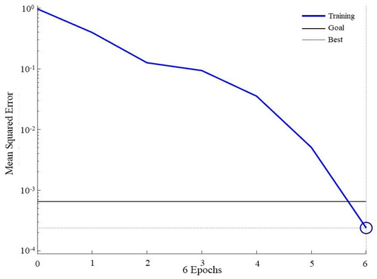
Figure 6.
Adaptive PSO-BP neural network prediction error variation.
The algorithm undergoes significant convergence after the sixth generation and achieves the error accuracy requirement, which brings convenience to the fault diagnosis when the microgrid fault samples are small. Compared with similar studies [30], the present study can achieve faster convergence. The advantages of this algorithm compared to the general traditional BP neural network and PSO-BP algorithm are as follows: it requires low training samples, can converge quickly and achieve the error requirement in a very small number of generations, and has a faster calculation and tighter accuracy.
5. Conclusions
This paper proposes a microgrid fault diagnosis method that is aimed at line protection equipment compared to traditional fault diagnosis methods based on fault current and fault voltage. When a circuit fault occurs, the corresponding protective equipment acts and sends an alarm signal. When the alarm signal is incorrect, it will cause a decrease in the accuracy of fault diagnosis. This paper utilizes the temporal logic relationship between line protection devices to correct alarm signals and form a high-accuracy and small-volume alarm signal set. The complete set of alarm signals is trained by the PSO-BP neural network, which converges in the sixth generation and meets the error requirements. It can achieve rapid fault location of the microgrid and lock in faulty equipment. This method has the following advantages: small training set size, fast convergence, and high diagnostic accuracy. As this fault diagnosis method in the paper is focused on line protection equipment, it can be applied to all types of short-circuit faults and has good application prospects.
Author Contributions
Conceptualization, L.W. and F.X.; methodology, F.Y.; software, F.Y.; validation, L.W., F.Y., F.X., and Z.W.; writing—review and editing, L.W., F.Y., F.X., Z.W., J.L., and W.Y.; visualization, F.X.; supervision, F.Y.; project administration, F.X.; funding acquisition, L.W. and F.X.; All authors have read and agreed to the published version of the manuscript.
Funding
This work was financially supported by the Heilongjiang Provincial Natural Science Foundation of China [No. LH2021F057], the Fundamental Research Funds in Heilongjiang Provincial Universities (No.145209312), the Science and Technology Project of State Grid Heilongjiang Electric Power Co., Ltd. [No.522418230004], and the Heilongjiang Province Discipline collaborative innovation Achievement Construction Project [No. LJGXCG2022-125].
Institutional Review Board Statement
Not applicable.
Informed Consent Statement
Not applicable.
Data Availability Statement
Not applicable.
Conflicts of Interest
The authors declare no conflict of interest.
References
- Shuai, H.; Fang, J.K.; Ai, X.M.; Tang, Y.; Wen, J.; He, H. Stochastic Optimization of Economic Dispatch for Microgrid Based on Approximate Dynamic Programming. IEEE Trans. Smart Grid 2019, 10, 2440–2452. [Google Scholar] [CrossRef]
- Xu, Q.; Zhang, C.; Wen, C.; Wang, P. A Novel Composite Nonlinear Controller for Stabilization of Constant Power Load in DC Microgrid. IEEE Trans. Smart Grid 2019, 10, 752–761. [Google Scholar] [CrossRef]
- Zheng, L.R.; Kandula, R.P.; Divan, D. Current-Source Solid-State DC Transformer Integrating LVDC Microgrid, Energy Storage, and Renewable Energy into MVDC Grid. IEEE Trans. Power Electron. 2020, 37, 1044–1058. [Google Scholar] [CrossRef]
- Li, Y.; Yang, Z.; Li, G.Q.; Zhao, D.; Tian, W. Optimal Scheduling of an Isolated Microgrid with Battery Storage Considering Load and Renewable Generation Uncertainties. IEEE Trans. Ind. Electron. 2019, 66, 1565–1575. [Google Scholar] [CrossRef]
- Huang, W.; Zhang, N.; Kang, C.; Li, M.; Huo, M. From demand response to integrated demand response: Review and prospect of research and application. Prot. Control Mod. Power Syst. 2019, 4, 12. [Google Scholar] [CrossRef]
- Wang, X.Q.; Yu, Y.Y.; Li, Y. Design and implementation of microgrid protection systems. Electr. Power 2011, 44, 78–81. [Google Scholar]
- Yu, K.; Lin, X.N.; Li, H. A Voltage Correction based Inverse-time Overcurrent Protection Scheme Considering Distributed Generation Stable Infeed Effect. Proc. CSEE 2017, 37, 716–726. [Google Scholar]
- Badal, F.R.; Das, P.; Sarker, S.K.; Das, S.K. A survey on control issues in renewable energy integration and microgrid. Prot. Control. Mod. Power Syst. 2019, 4, 8. [Google Scholar] [CrossRef]
- Muhammad, F.Z.; Mohamed, B.; Elhoussin, E.; Muyeen, S.M.; Techato, K.; Guerrero, J.M. Microgrid Transactive Energy: Review, Architectures, Distributed Ledger Technologies, and Market Analysis. IEEE Access 2020, 8, 19410–19432. [Google Scholar]
- Li, Y.; Wang, R.N.; Yang, Z.H. Optimal Scheduling of Isolated Microgrids Using Automated Reinforcement Learning-Based Multi-Period Forecasting. IEEE Trans. Sustain. Energy 2022, 13, 159–169. [Google Scholar] [CrossRef]
- Hou, X.; Sun, Y.; Zhang, X.; Lu, J.; Wang, P.; Guerrero, J.M. Improvement of Frequency Regulation in VSG-Based AC Microgrid Via Adaptive Virtual Inertia. IEEE Trans. Power Electron. 2020, 35, 1589–1602. [Google Scholar] [CrossRef]
- Zhang, L.; Zheng, H.; Wan, T.; Shi, D.; Lyu, L.; Cai, G. An integrated control algorithm of power distribution for islanded microgrid based on improved virtual synchronous generator. IET Renew. Power Gener. 2021, 15, 2674–2685. [Google Scholar] [CrossRef]
- Xu, B.; Yin, X.G.; Wang, Y.; Zhang, Z.; Hao, X.; Chen, Z.Z. Fault Diagnosis Method of Power System Based on Fuzzy Time Petri Net. Autom. Electr. Power Syst. 2018, 42, 70–76. [Google Scholar]
- Chen, W.D.; Feng, B.; Tan, Z.G.; Wu, N.; Song, F. Intelligent fault diagnosis framework of microgrid based on cloud-edge integration. Energy Rep. 2022, 8, 131–139. [Google Scholar] [CrossRef]
- Ran, G.; Liu, J.; Li, C.; Lam, H.-K.; Li, D.; Chen, H. Fuzzy-Model-Based Asynchronous Fault Detection for Markov Jump Systems with Partially Unknown Transition Probabilities: An Adaptive Event-Triggered Approach. IEEE Trans. Fuzzy Syst. 2022, 30, 4679–4689. [Google Scholar] [CrossRef]
- Jiang, X.; Wang, D.; Zhang, C.L. A Complete Analytic Method for Fault Diagnosis of Power Systems Based on Model-based Diagnosis for Dimensionality Reduction. Proc. CSEE 2016, 36, 6371–6378. [Google Scholar]
- Wang, R.; Sun, Q.; Tu, P.; Xiao, J.; Gui, Y.; Wang, P. Reduced-Order Aggregate Model for Large-Scale Converters with Inhomogeneous Initial Conditions in DC Microgrids. IEEE Trans. Energy Convers. 2021, 36, 2473–2484. [Google Scholar] [CrossRef]
- Sneath, J.; Rajapakse, A.D. Fault Detection and Interruption in an Earthed HVDC Grid Using ROCOV and Hybrid DC Breakers. IEEE Trans. Power Deliv. 2016, 31, 973–981. [Google Scholar] [CrossRef]
- Zhang, Z.H.; Yang, G.H. Time-varying threshold-based fault detection for a class of uncertain non-linear systems in strict-feedback form. IET Control Theory Appl. 2016, 10, 2149–2159. [Google Scholar] [CrossRef]
- Xu, B.; Yin, X.G.; Wu, D.L.; Pang, S.; Wang, Y.K. An Analytic Method for Power System Fault Diagnosis Employing Topology Description. Energies 2019, 12, 1770. [Google Scholar] [CrossRef]
- Qian, J.C.; Jiang, L.; Song, Z.H. Locally linear back-propagation based contribution for nonlinear process fault diagnosis. IEEE-CAA J. Autom. Sin. 2020, 7, 764–775. [Google Scholar] [CrossRef]
- Hanbo, Z.; Wei, W.; Xiaogang, L.I.; Linan, W.; Yuquan, L.I.; Jinhua, H. Fault Diagnosis Method of Power Transformers Using Multi-class LS-SVM and Improved PSO. High Volt. Eng. 2014, 40, 3424–3429. [Google Scholar]
- Ran, G.; Chen, H.; Li, C.; Ma, G.; Jiang, B. A hybrid design of fault detection for nonlinear systems based on dynamic optimization. IEEE Trans. Neural Netw. Learn. Syst. 2022. early access. [Google Scholar] [CrossRef]
- Wang, T.; Zhang, G.; Zhao, J.; He, Z.; Wang, J.; Pérez-Jiménez, M.J. Fault Diagnosis of Electric Power Systems Based on Fuzzy Reasoning Spiking Neural P Systems. IEEE Trans. Power Syst. 2015, 30, 1182–1194. [Google Scholar] [CrossRef]
- Chine, W.; Mellit, A.; Lughi, V.; Malek, A.; Sulligoi, G.; Pavan, A.M. A novel fault diagnosis technique for photovoltaic systems based on artificial neural networks. Renew. Energy 2016, 90, 501–512. [Google Scholar] [CrossRef]
- Lan, T.; Jermsittiparsert, K.T.; Alrashood, S.; Rezaei, M.; Al-Ghussain, L.A.; Mohamed, M. An Advanced Machine Learning Based Energy Management of Renewable Microgrids Considering Hybrid Electric Vehicles’ Charging Demand. Energies 2021, 14, 569. [Google Scholar] [CrossRef]
- Liu, W.; Wang, T.; Zang, T.; Huang, Z.; Wang, J.; Huang, T.; Wei, X.; Li, C. A Fault Diagnosis Method for Power Transmission Networks Based on Spiking Neural P Systems with Self-Updating Rules considering Biological Apoptosis Mechanism. Complexity 2020, 3, 2462647. [Google Scholar] [CrossRef]
- Nguyen, T.-T.; Ngo, T.-G.; Dao, T.-K.; Nguyen, T.-T. Microgrid Operations Planning Based on Improving the Flying Sparrow Search Algorithm. Symmetry 2022, 14, 168. [Google Scholar] [CrossRef]
- Qin, H.; Yang, R.; Guo, C.; Wang, W. Fault diagnosis of electric rudder system using PSOFOA-BP neural network. Measurement 2021, 183, 110058. [Google Scholar] [CrossRef]
- Eldeghady, G.S.; Kamal, H.A.; Hassan, M.A.M. Fault diagnosis for PV system using a deep learning optimized via PSO heuristic combination technique. Electr. Eng. 2023. [Google Scholar] [CrossRef]
- Jiang, C.D.; Xia, Z.L. Application of a Hybrid Model of Big Data and BP Network on Fault Diagnosis Strategy for Microgrid. Comput. Intell. Neurosci. 2022, 2022, 1554422. [Google Scholar] [CrossRef]
- Chen, J.H.; Gao, Y.J.; Jin, Y.W. Microgrid fault diagnosis method based on MODWT and BP neural network. J. Shanghai Univ. Electr. Power 2021, 37, 57–60. [Google Scholar]
- Hua, H.; Qin, Z.; Dong, N.; Qin, Y.; Ye, M.; Wang, Z.; Chen, X.; Cao, J. Data-Driven Dynamical Control for Bottom-up Energy Internet System. IEEE Trans. Sustain. Energy 2022, 13, 315–327. [Google Scholar] [CrossRef]
- Zhao, J.R.; Wang, Z.H.; Wang, J.D.; Zhang, H. Fault Characteristics of Microgrid and Protection Strategies. J. Shanghai Jiao Tong Univ. 2015, 49, 913–922. [Google Scholar]
- Jamali, S.; Ranjbar, S.; Bahmanyar, A. Identification of faulted line section in microgrids using data mining method based on feature discretization. Int. Trans. Electr. Enegry Syst. 2020, 30, 2104–2119. [Google Scholar]
- Liang, M.H. Microgrid Fault Characteristic Analysis and The Study on Protection Principle. Wuhan Sch. Electr. Electron. Eng. HUST 2011, 1–49. [Google Scholar]
- Li, Y.L.; Jin, Q.; Li, B.T.; Li, Z. Application of Inverse-Time Overcurrent Protection Based on Low Voltage Acceleration in Micro-Grid. Trans. Tianjin Univ. 2011, 44, 955–960. [Google Scholar]
Disclaimer/Publisher’s Note: The statements, opinions and data contained in all publications are solely those of the individual author(s) and contributor(s) and not of MDPI and/or the editor(s). MDPI and/or the editor(s) disclaim responsibility for any injury to people or property resulting from any ideas, methods, instructions or products referred to in the content. |
© 2023 by the authors. Licensee MDPI, Basel, Switzerland. This article is an open access article distributed under the terms and conditions of the Creative Commons Attribution (CC BY) license (https://creativecommons.org/licenses/by/4.0/).