1. Introduction
In order to describe the approximate reasoning typically used by humans, in 1965, Zadeh [
1] introduced the concept of fuzzy sets. Then, fuzzy logic appeared as an extension of classical set theory, providing an attractive solution to easily model human reasoning. In a fuzzy system, the knowledge given by human experts is modeled through if-then rules from which the system can infer a valid result despite natural language uncertainty [
2]. The application of a Fuzzy Inference System (FIS) in many fields, such as control [
3], modeling [
4], classification [
5,
6,
7], energy [
8], health [
9], among others [
10,
11,
12] has encouraged the search for developmental tools capable of providing facilities for the design, simulation, and implementation of fuzzy systems to either standard processor or specific hardware devices. Most of the available software tools for the design of FISs are developed by the scientific community and are open source, some of them are FISDeT [
13], fuzzycreator [
14], FisPro [
15], jFuzzyLogic [
16], and JUZZY Online [
17], which is an online toolkit. In addition, there are commercial tools, such as
Fuzzy Logic Toolbox for MATLAB [
18]. This toolbox has been used extensively in engineering and computer science to design fuzzy systems [
19,
20,
21]. MATLAB has another open source toolbox for Interval Type-2 Fuzzy Logic Systems (IT2-FLSs) [
22]. The availability of these software tools empowers FIS designers to create models effectively, regardless of their expertise level. The user-friendly interfaces offered by these tools facilitate the creation of FIS models by providing intuitive functionalities and visualization capabilities [
23]. However, fuzzy systems implemented in hardware have shown higher performance than software implementations [
24]. For this reason, different strategies for automatic hardware synthesis of FISs have been proposed in the literature.
Hardware implementation of fuzzy systems has the potential to greatly speed up processing time, but comes with its own set of challenges. First, an advanced knowledge of hardware is required to efficiently design the FIS. In addition, according to the complexity of the system this task could take a lot of time and effort. On the other hand, every modification made to the code will require the system to be re-synthesized on the device, which can be a time-consuming process.
Over the years, the application of fuzzy logic in control and decision-making problems has increased, leading to various approaches for hardware implementation of fuzzy algorithms. First, a design methodology for the implementation of fuzzy systems based on Hardware Description Language and Very High Speed Integrated Circuits (VHDL) specification improving their performance was proposed by Hollstein et al. in [
25]. Since then, CAD tools were presented by research groups with an interest on these kind of systems. One of them is
Xfuzzy [
26], this tool enables the development of fuzzy systems through modules that convert a language for fuzzy logic (XFL) description into Look-Up tables for Field Programmable Gate Array (FPGA) implementation. At this time, the
Xfuzzy environment is in its 3.5 version which contains new features to improve and accelerate the design flow of fuzzy systems on hardware devices. In the literature, there are works which leverage the
Xfuzzy capabilities to explore for fully automated methodologies that covers the entire process, from the description of the system to implementation of fuzzy systems on VHDL [
27], while others take advantage of tools such as MATLAB and Simulink to generate the corresponding files with the parameters of the system [
28]. The goal of these methods is to accelerate the creation and deployment of fuzzy systems on hardware. However, there are limitations such as the need for extensive hardware design knowledge and the need for a computer to perform synthesis every time code is modified.
The limitations of the current implementation process for fuzzy systems in hardware have motivated the need for a more adaptable solution. To address this, we propose a VHDL code that incorporates a graphical user interface (GUI) for designing an FIS. The VHDL program is pre-synthesized and integrated with the interface, enabling the user to experiment with various input parameters without the need for re-synthesis the code on the FPGA. Additionally, the GUI provides an on-screen display of the input/output membership functions. Therefore, our proposed solution represents a significant advance in the implementation of fuzzy systems on hardware devices, providing a flexible and user-friendly approach for the design and implementation.
In order to verify the effectiveness of our proposed approach, experiments were conducted on two similar SoC devices, VEEK-MT and VEEK-MT2. On both devices, an FIS was implemented and evaluated by introducing data for simulation. After a successful validation of the results, the same experiments were repeated using the proposed GUI, obtaining the expected results. Finally, the results obtained by performing the same experiment using the Fuzzy Logic Toolbox available on MATLAB, JUZZY Online, and FISDeT were compared.
The current study highlights the importance of developing tools for the automatic design of FISs in the fuzzy logic community. In this paper, is presented an adaptable Fuzzy Hardware Tool that facilitates the direct implementation of FISs in hardware through a GUI. The proposed tool enables the user to select features such as the type of membership functions and fuzzy rules. Furthermore, the tool is pre-synthesized in VHDL code and implemented on a FPGA, providing the user with the opportunity to design the FIS without the need for a computer.
This paper is organized as follows:
Section 2 presents the theoretical background on a Mamdani-type FIS.
Section 3 presents an overview of the existing methodologies for the implementation of fuzzy systems on software and hardware.
Section 4 describes the approach proposed in this work, and the design stages of the FIS in VHDL and the GUI.
Section 5 presents the implementation, experimental tests, and results using the
Fuzzy Hardware Tool.
Section 6 presents a performance comparison and discussion of the results. Finally,
Section 7 summarizes the conclusions and future work of this research.
2. Theoretical Background
This section aims to provide a theoretical background related to Mamdani-type Fuzzy Inference Systems, which are employed in this project. It describes the general process of Fuzzification, Inference, and Defuzzification, highlighting the methods used in this work.
2.1. Mamdani Fuzzy Inference System
Fuzzy systems are convenient tools to deal with uncertain and vague concepts commonly found in natural language. These systems have the ability to represent human reasoning translating the experts’ knowledge into fuzzy if-then rules from which a valid result may be inferred. The above is achieved by applying fuzzy logic to transform crisp values into linguistic variables. All the possible values of a linguistic variable are established over a
universe of discourse [
2].
One of the most common methods of inference for fuzzy systems based on linguistic rules is that presented by Mamdani and Assilian [
29]. In order to illustrate the general idea, consider a Mamdani-type FIS with a two-rule system where each rule comprises two antecedents and one consequent, which is analogous to a dual-input and single-output fuzzy system. This fuzzy system with two non-interactive inputs,
and
, and a single output
y can be described by a collection of
r linguistic if-then propositions in the form [
30]:
where
and
are the fuzzy sets representing the
k-th antecedent pairs and
is the fuzzy set representing the
k-th consequent. These collections of fuzzy if-then rules model the qualitative features of human reasoning and be used by a fuzzy system that is composed by the three main stages; Fuzzification, Inference, and Defuzzification. In this work, fuzzy logic was applied to convert control rules supplied by humans into an automatic control strategy for a steam engine.
2.1.1. Fuzzification
The process of converting crisp quantities into fuzzy values is called Fuzzification. These fuzzy values are known as linguistic variables whose states are described by linguistic terms. Linguistic terms are defined by their Membership Function (MF), which is a graphical representation of the participation of each input in the system. An input can be evaluated in the MF to express the membership degree. Usually, this number has a value between [0, 1]. In this interval, 0 and 1 represent the non membership and full membership for the input, respectively.
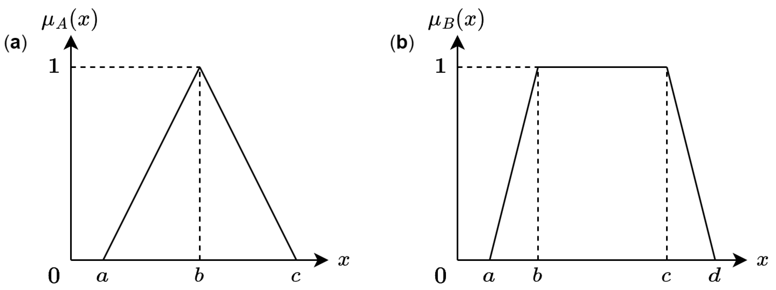
In fuzzy logic, each input and output can be associated with a different MF whose shape can be symmetrical or asymmetrical. However, triangular and trapezoidal shapes are the most common MFs for hardware applications [
2]. The values which represent the membership degree are defined by Equation (
2) for triangular MF and Equation (
3) for trapezoidal MF:
where
and
are the corresponding membership degree for the input
x and the parameters
a,
b,
c and
d are shown in
Figure 1 which is a graphical representation of these two MFs.
2.1.2. Inference
At this stage, the base of rules that describe the behavior of the FIS is contained. This set of rules is in the form (
1). Here, the if-then rules are evaluated according to the results obtained in the Fuzzification process. For the Mamdani-type system studied in this work, the evaluation was performed using a
Minimum implication operation. Therefore, the output of the
r rules will be:
where
and
correspond to the firing strength.
2.1.3. Defuzzification
The Defuzzification process mainly consists in obtaining a crisp value from the Inference stage output.
There are several methods to calculate the output of the Defuzzification stage, such as centroid, Center of Gravity (COG), Center of Height (COH), among others. The COH method is shown in Equation (
5):
where
is the maximum height and
represents the firing strength of the
m-th consequent.
The COH method uses the maximum height of the membership functions of the consequent ; this value is multiplied by the firing strength that is obtained in the inference stage. The products of these multiplications are added from 1 to n, where n is the number of active membership functions. Finally, the resulting sum is divided by the sum of all the values of the firing strength .
3. Related Work
In the literature different approaches and design methodologies have been reported, aiming at the same objective: the implementation of fuzzy logic systems in a wide range of problems.
Currently, researchers are taking advantage of using commercial tools such as MATLAB for implementing fuzzy systems. For instance, ref. [
31] presented a MATLAB/Simulink implementation of a interval type-3 fuzzy inference system. The authors demonstrated the effectiveness of their approach through two practical examples: identification of a chaotic system and control of a robotic manipulator. In addition to its functionality, MATLAB also includes a
Fuzzy Logic Toolbox, that allows the users to construct an FIS using a GUI [
18]. This toolbox was employed in [
19] to design a fuzzy system for the control of ventilation systems. In order to allow the intuitive implementation of IT2-FLSs, Taskin et al. [
22] presents an open source Toolbox for MATLAB environment, it has the capacity to cover all stages of the IT2-FLSs design through a GUI that facilitates the development of the system.
On the other hand, there are several open-source software alternatives available for creating and executing fuzzy systems. Many of these alternatives have been developed by the scientific community and are shared in the form of libraries, source code, or toolkits [
23]. Among the available options, we can highlight Java-based toolkits for the implementation of a type-1 FIS [
15,
16]. Both of these provide visualizations and a graphical interface. In [
17] an online toolkit, based on Java, allows the user to create a type-1 and interval type-2 FIS without familiarity with Java. Moreover, this online toolkit offers the option to plot the FIS and the control surface of the system. Recently, a Python-based toolkit for designing type-1 fuzzy systems and creating fuzzy rules was introduced in [42]. This implementation utilizes the
pyfuzzy library. In addition, ref. [
14] has proposed another Python-based toolkit that allows the construction of type-1 and type-2 fuzzy sets from data automatically.
The existing approaches mentioned above offer many advantages and features, but they do not provide the capability to implement an FIS directly on hardware devices. FPGAs, on the other hand, are known for their ability to parallelize computations, which can significantly accelerate the execution of complex algorithms. By implementing a fuzzy system on an FPGA, the computational performance can be greatly enhanced compared to software-based implementations, enabling real-time and high-speed processing of fuzzy logic operations. However, it is important to note that implementing a fuzzy system on an FPGA requires a deep understanding of hardware design. To achieve the implementation of an FIS on hardware, the researchers could design their own VHDL or Verilog code, such as the fuzzy logic controller presented in [
32]. Or, leverage of the available tools that support the hardware implementation such as
Xfuzzy [
26] which is used in [
33] to design fuzzy logic system for predicting productivity in agriculture. The
Xfuzzy environment is one of the most attractive options for FIS design in hardware, because it provides a path to implement an XFL description of a fuzzy system on an FPGA. Furthermore, the XFL specification can be translated into a VHDL description that can be synthesized on an FPGA or Application Specific Integrated Circuit (ASIC). This environment integrates several tools for fuzzy systems design, covering description, tuning, verification, and synthesis stages [
34,
35].
In [
28] are discussed two tools for hardware synthesis included in the
Xfuzzy environment. They achieve to demonstrate that the hardware implementation of fuzzy systems can be accelerated, as well as facilitate the exploration of the design space for different applications if a design flow, supported by the utilization of parameterized cell libraries and CAD tools, is available. The first tool, XFVHDL, is focused on the generation of VHDL code that can be synthesized and implemented on a reconfigurable device such as an FPGA. The second one, XFSG, is based on
Xilinx System Generator which is integrated into the MATLAB environment. This tool includes a library named
XfuzzyLib that includes, in addition to Simulink’s basic building blocks, components to describe fuzzy logic controllers. Those components vary in the number of inputs, the connective used to calculate the rule activation degrees, and the Defuzzification method. Since the building blocks used to describe fuzzy logic controller architectures are fully parametrizable, it is possible to adapt them according to the required application. The main purpose of the XSFG tool is to automate the design process of a fuzzy system by providing a file containing the Simulink model and a MATLAB file with the parameters that define its components.
To simplify the implementation of fuzzy systems on hardware, in [
36] an Intellectual Property (IP) Core for two-input/single-output FIS that can be set into a SoC was developed. This module used as a building block permits the user to develop an FIS through a configuration interface without focusing on hardware details. In this interface, users can choose between trapezoidal or triangular membership functions (up to three per input) and Defuzzification methods, according to whether the FIS is Mamdani or Sugeno. The implementation of the IP block was performed on a Zynq SoC using Vivado CAD tool; moreover, this configurable IP block is independent of the target hardware, allowing the system to be synthesized and implemented in a variety of FPGAs.
The development of different methodologies for fuzzy systems implementation has provided hardware designers with the opportunity to select the best approach for their projects. However, such techniques often require a deep understanding of hardware design, posing a challenge for users interested in exploring the potential of FPGAs for their research. In addition, the need to re-synthesize the system for every modification made to the code can result in a time-consuming process and remains a significant limitation for the existing approaches towards hardware implementation of fuzzy systems.
In
Table 1, is presented a comparison of the general features of some tools for the design of fuzzy systems available in the literature. Remarking that only few of them provides a path to implement the system in hardware devices. The adaptable tool for the design of an FIS in hardware presented in this work offers several advantages. While many available tools already provide a GUI for system construction and data visualization, the proposed GUI-touchscreen takes user interaction to a new level. It offers an intuitive and user-friendly approach to interacting with the fuzzy system implemented on an FPGA, eliminating the need of a deep understanding of VHDL or Verilog. Thanks to its adaptable features, the VHDL code is previously synthesized on the FPGA, users can make modifications to membership functions, inference rules, and other system components without the requirement of re-synthesizing the code. As a result, rapid prototyping and experimentation become possible, greatly facilitating the design process.
4. Experimental Test and Results
The Fuzzy Hardware Tool is a proposal for beginners or experts in the area of fuzzy systems. With this proposal, FIS designers will be able to interact through a multi-touch screen with an FIS implemented in an SoC with FPGA device and processor. The Fuzzy Hardware Tool is a didactic environment to design, simulate, and implement a Mamdani FIS. The tool lets you select and configure inputs, output, membership functions, and rules.
This section explains how the two parts of the Fuzzy Hardware Tool, the VHDL and the GUI, are designed. The first part is the code design, then the VHDL design examines the main variables and the process to obtain the result of the given problem. The GUI design is concerned with the visual interface where the problem is designed by the users.
4.1. FIS VHDL Design
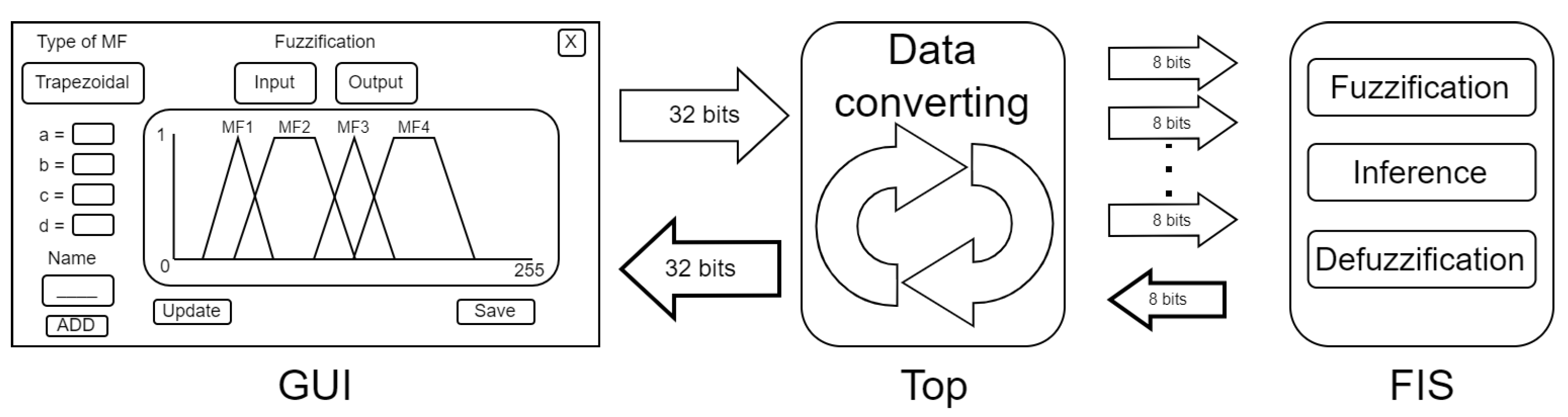
The FIS is divided into four stages: Top, Fuzzification, Inference, and Defuzzification. The GUI was programmed using variables with 32 bits and the VHDL code used variables with other sizes of bits, for example, the FIS has 8 bits, for this reason a converter between the data from the GUI is used.
Figure 2 shows the basic diagram of the
Fuzzy Hardware Tool, the following paragraphs explain in detail each of these stages.
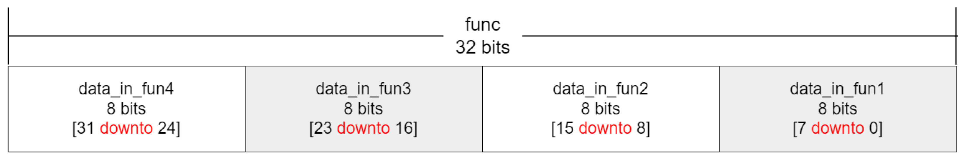
TOP is the stage programmed in VHDL code and is the connection between GUI in C/C++ and the FIS. The FIS in VHDL receives variables with different bit sizes that are joined into a bus of 32 bits. The first bus from the GUI is called
func. This bus is used for the three parameters of the triangular MF or four parameters for the trapezoidal MF and is the union of four variables, as shown in the
Figure 3.
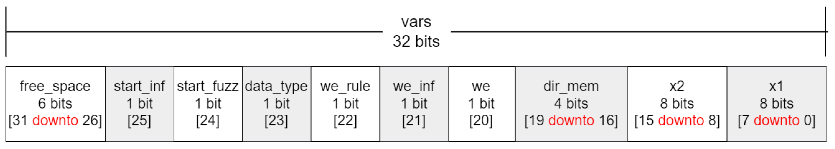
The second bus is
vars which contains nine variables to use in the FIS. This bus has 6 bits empty, the free space is to complete the 32 bits of the bus.
Figure 4 shows the diagram of
vars. In this case,
vars contains the flags to start fuzzification (
start_fuzz), read or write the MFs of the inputs (
we_fuzz), start inference (
start_inf), read or write the MFs of the output (
we_defuzz), read or write the rules (
we_rule), MF type selection (
data_type), or choose the stored rules (
dir_mem). It also has the values of the inputs (x1, x2).
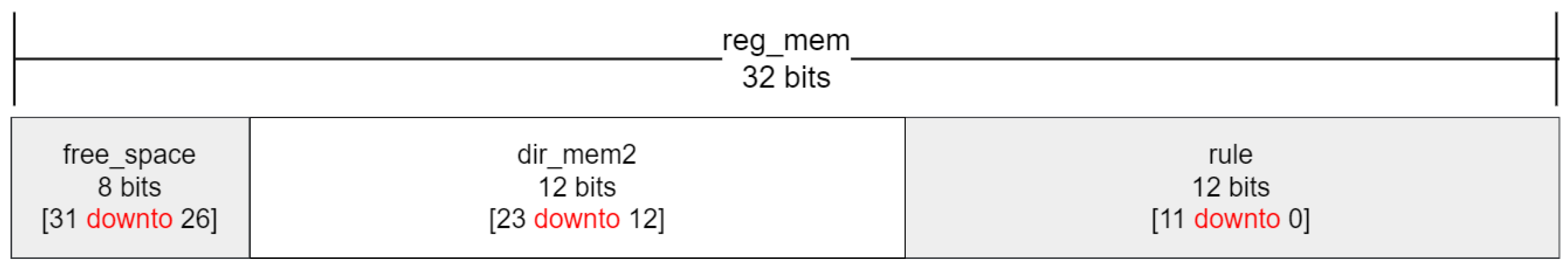
The third bus is
reg_mem which contains two variables to use in the FIS, and one empty variable with 8 bits, as shown in
Figure 5. In addition,
reg_mem contains a 12-bit memory address pointer for the rules (
dir_mem2) and another 12 bits to save the rules (
rule).
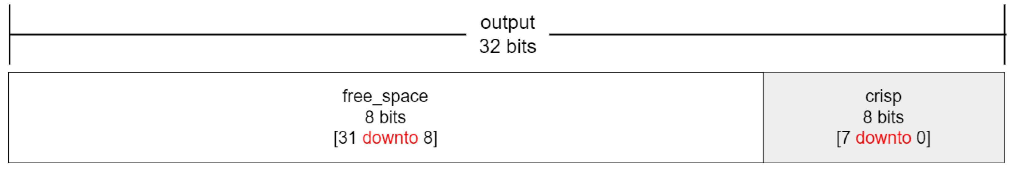
The last one is the bus
output. This bus, unlike the others, receives the crisp value from the FIS in VHDL code and after it is sent to the GUI, the bus
output has 24 bits of free space because the crisp value only has 8 bits, as represented in
Figure 6.
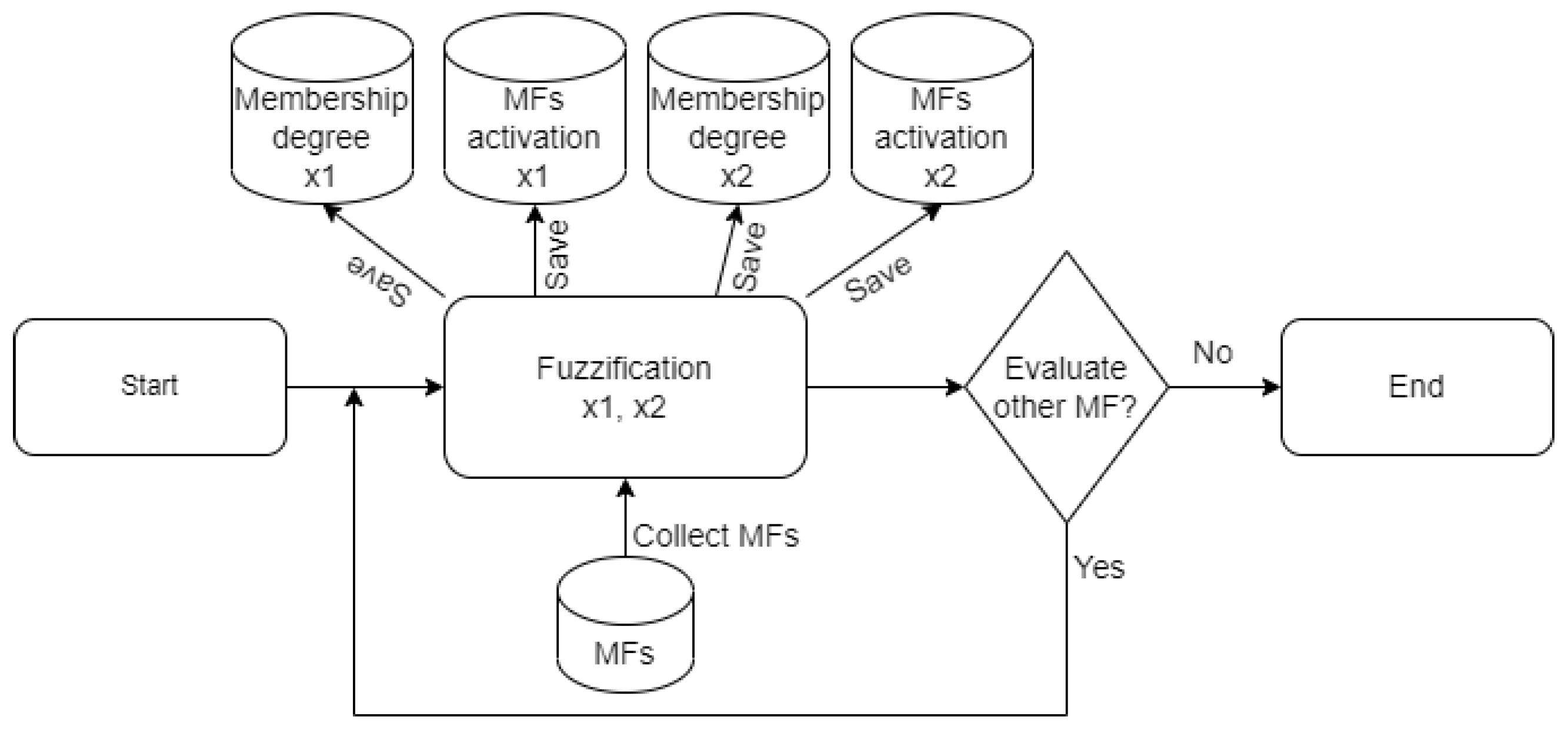
Fuzzification: The first stage of the FIS is when the tool receives the MFs parameters and calculates the membership degree with Equations (
2) and (
3). The FIS has two linguistic variables
x1 and
x2 and one output, also the users can add up to 15 MFs for each linguistic variable. The supported types of MFs are triangular and trapezoidal, which are the most common for hardware due their ease of implementation and their simplicity [
2,
32]. The process is started when the input called “start_fuzz” is activated. The process consists of a loop with all MFs evaluated with x1 and x2; the results are saved in four registers, two registers for the membership degree to x1 and x2, and other two to indicate which MFs are activated. The activated MFs are used in the Inference stage.
Figure 7 shows the process.
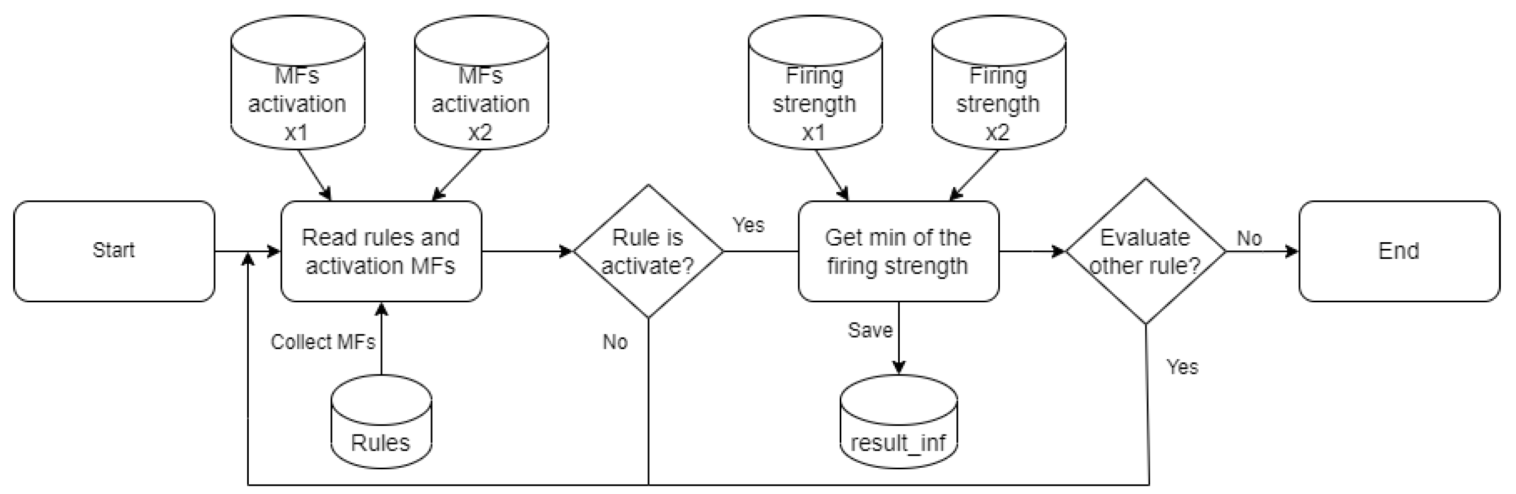
Inference: In this stage, the rules of the FIS are evaluated. Through a loop, each MF is evaluated and compared to define which MF is activated for the input of the FIS. Then the firing strength is activated, and all the firing strengths are compared to compute the min method (see Equation (
4)). The result is saved in a register called
result_inf. When the evaluation of the rules is finished, a variable is activated to indicate that the next stage is ready to start.
Figure 8 shows the diagram of the process.
Defuzzification: This is the last stage of the FIS, when the crisp value is obtained. At this stage, the COH is computed using Equation (
5). This stage uses the variables from the previous stages.
The VHDL design of the FIS considers the following characteristics and constraints:
Contains only two linguistic variables for the input (x1 and x2).
Contain only one output.
Each linguistic variable can have up to 15 MFs.
The MFs are trapezoidal and triangular type.
The number of fuzzy rules depends on the number of MFs for each linguistic variable.
Use the min method for the inference.
Use the COH method for defuzzification stage.
The universe of discourse is discretized in 8 bits.
4.2. Graphic User Interface Design
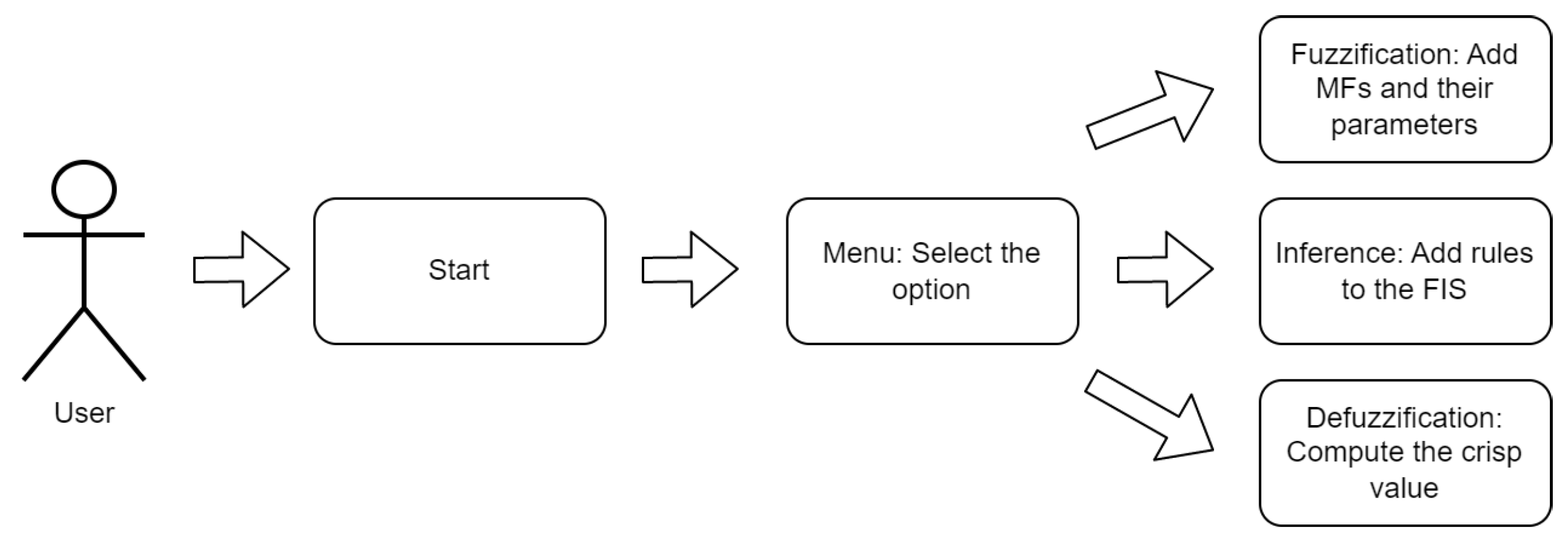
This section explains the graphic interface that the user uses to manage the FIS. To explain the main functionality of the GUI, a Unified Modeling Language (UML) diagram is shown in
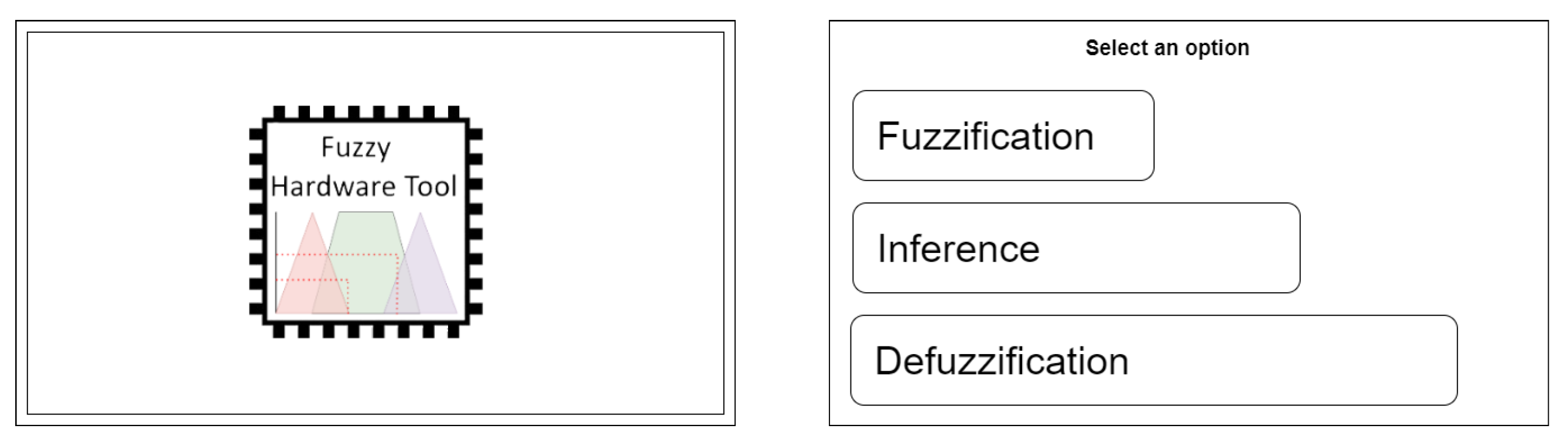
Figure 9. A user starts the FIS and the first screen shows the tool logo. This screen is just to provide a welcome. When the user touches the screen, it changes to the second screen, which is the menu. In this screen, the user selects an option to interact with the FIS, as shown in
Figure 10. Because the FIS has three stages, the menu screen has three options. The first option is Fuzzification, the second option is Inference, and the last option is Defuzzification.
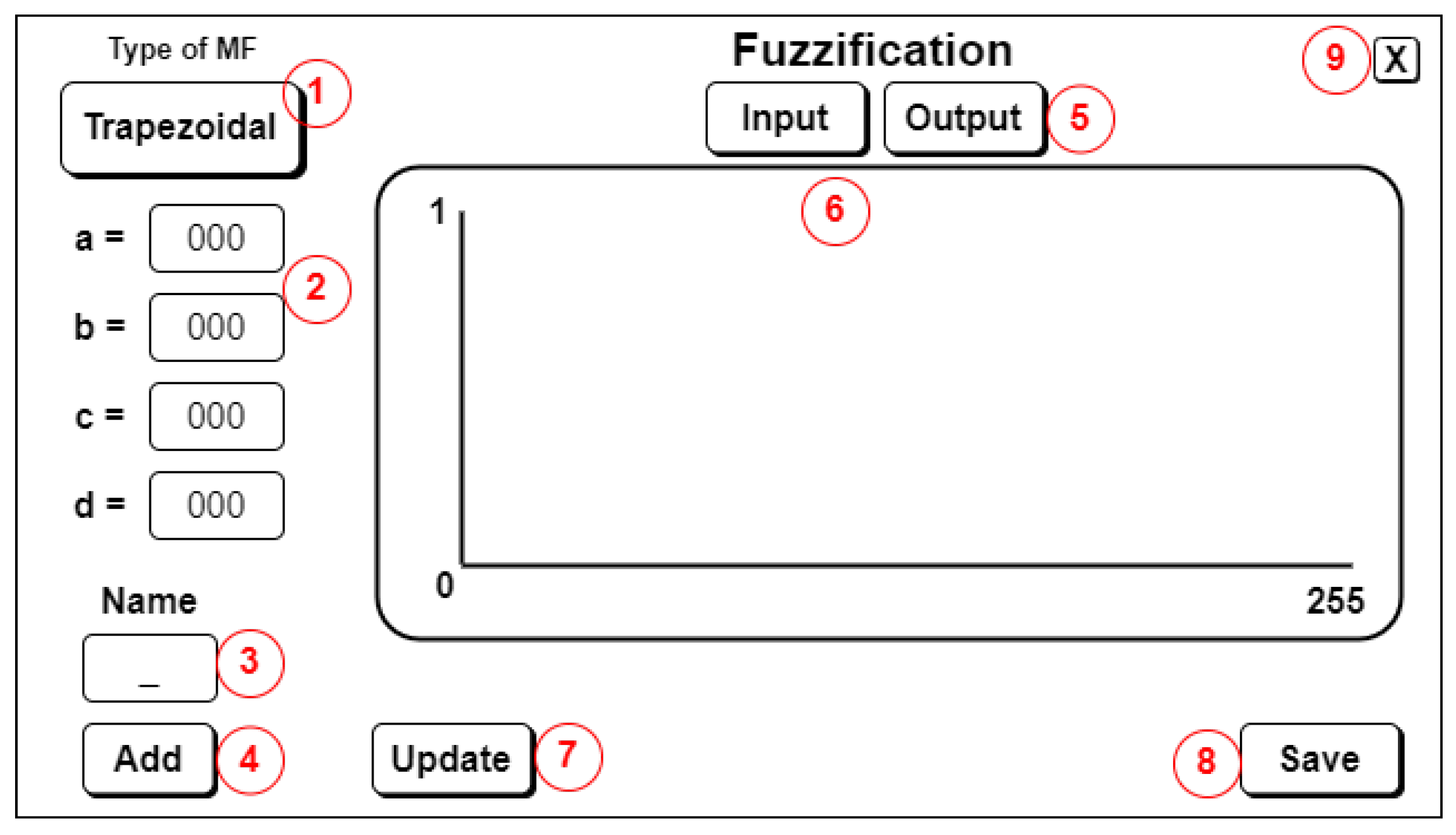
The Fuzzification screen has some options and features.
Figure 11 shows the GUI of Fuzzification. In this screen, there are nine options, which are explained bellow. (1) the first thing to do is add an MF, the first step is to select the MF type; (2) put the parameters of the MFs, three for the triangular MF and four for the trapezoidal MF (see
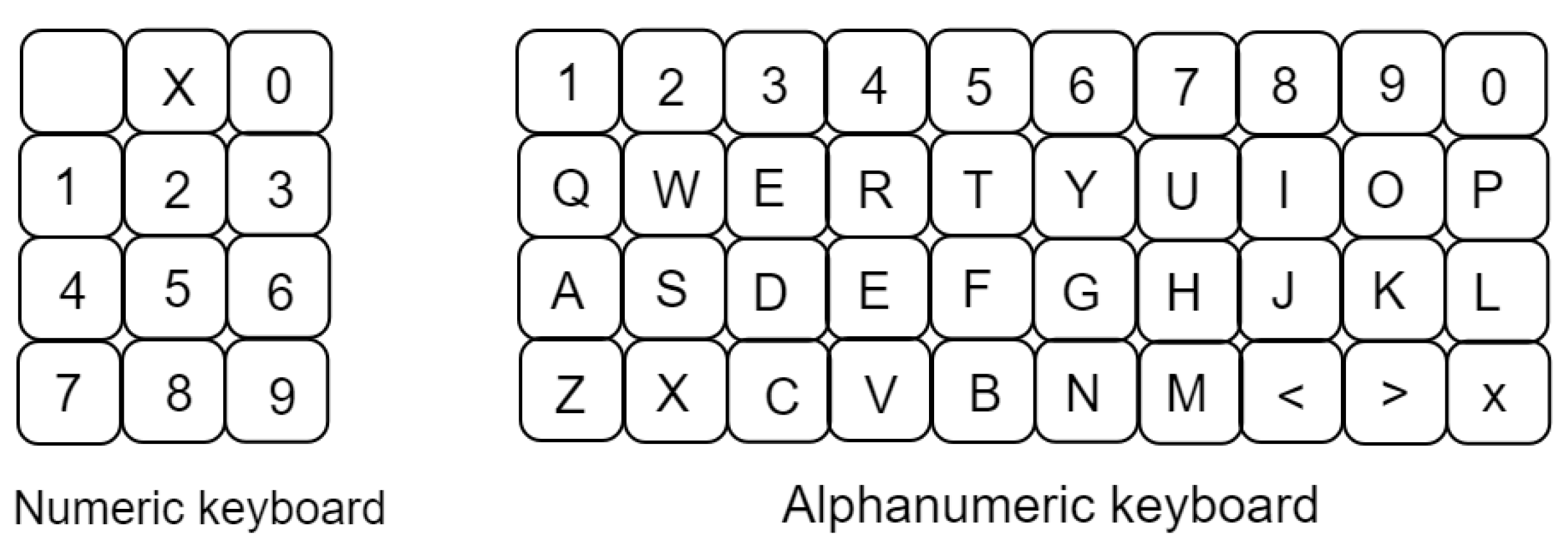
Figure 1); (3) when the user touches the textbox a numeric keyboard will appear, this tool is used to make it easier add data to the FIS. After that, the user can add a name for the MF in option 3; an alphanumeric keyboard appears in this part, as shown in
Figure 12. Both keyboards are programmed to be used in other parts of the FIS when the user needs to capture a name or numeric label; (4) this option is to add the MF to the FIS; (5) this option is to select between input or output of the FIS; (6) the viewfinder is to see the whole discourse, the type of MF and their parameters. In addition, by adding option (5) it is possible to change between inputs and output of the FIS; (7) this option is to update the parameters and type of MFs; (8) it is used to save the parameters of the Fuzzification stage; and (9) to close the Fuzzification stage and return to the main menu.
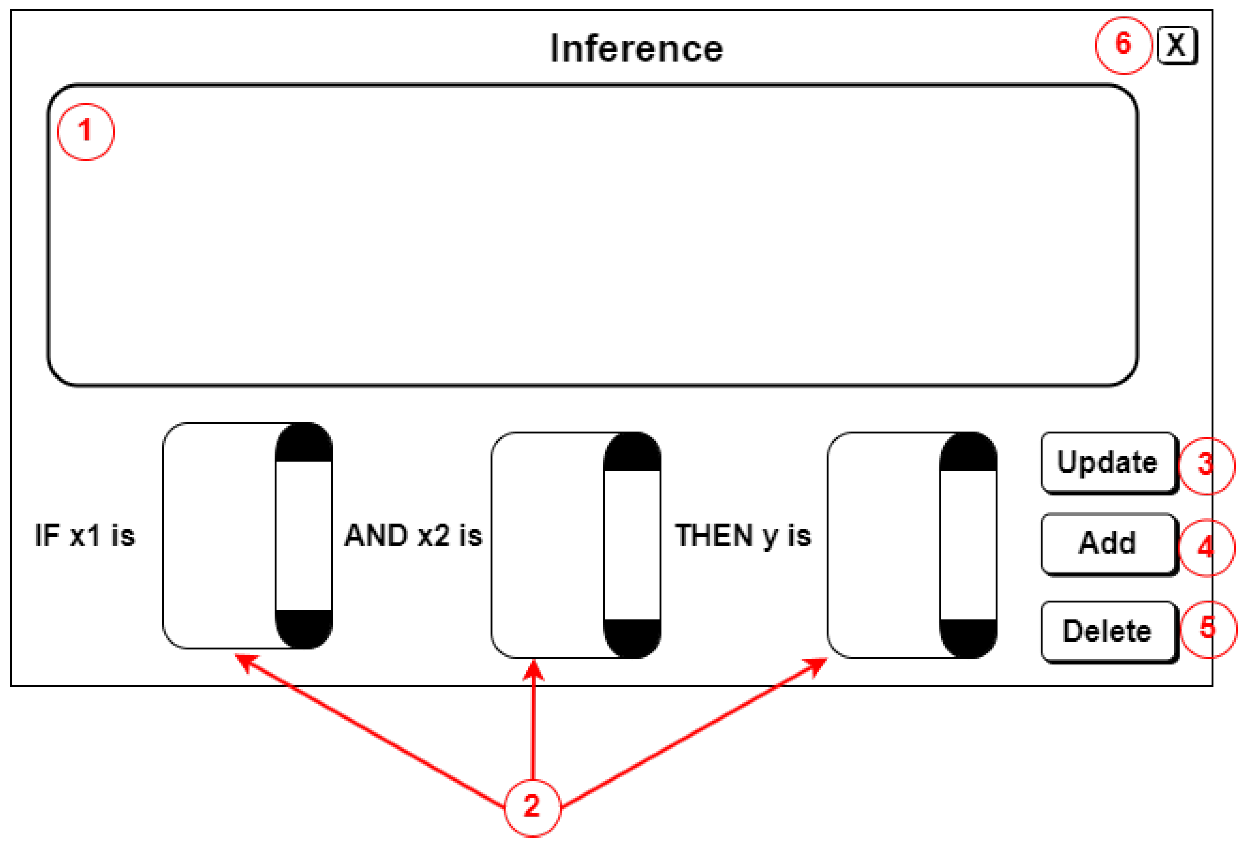
The next screen is the Inference stage. The interface is divided into six options, as shown in
Figure 13. (1) Shows the rules when the user adds them. This is called the inference display. In this part, the user can create fuzzy rules with the data from the previous stage denoted by option (2); (3) this option is to add the rule to the inference display; (4) and (5) allow the user to update or delete rules; and (6), when the user finishes adding rules, they can use the button X in the corner of the screen and return to the main menu.
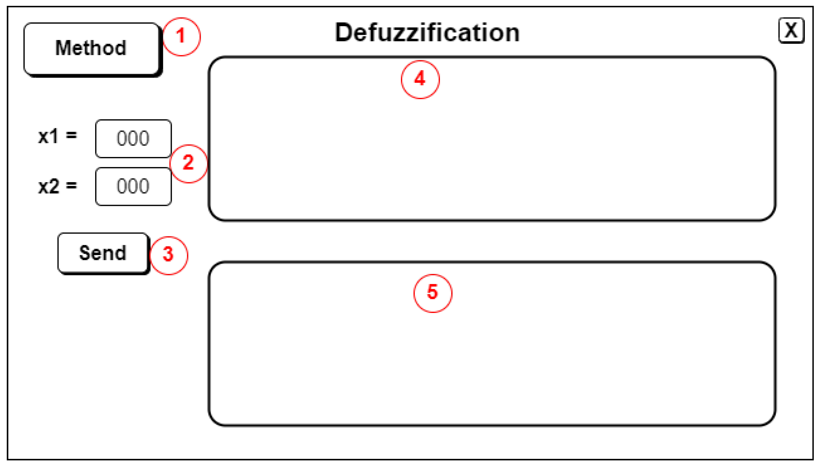
Figure 14 is the last screen. This is the Defuzzification stage, where there are five options. (1) Selects the Defuzzification method, which, as mentioned above, is the COH method; (2) the user can add the values for the x1 and x2 in order to calculate the crisp value; (3) computes the crisp value; (4) displays the MFs of the inputs, x1 and x2; and (5) prints the MFs output of the FIS.
In summary, the design of the Fuzzy Hardware Tool consists of two main components. The first component is the FIS in VHDL code. The second component is the GUI that allows users to design FISs in hardware. To facilitate the communication between these components, the High-Speed Mezzanine Card (HSMC) bus is used. The HSMC bus, integrated into the VEEK-MT and VEEK-MT2 SoCs, serves as a high-speed interface developed by Intel specifically for expanding connectivity between Intel FPGAs. It enables efficient data transfer and synchronization between the VHDL code and the GUI. The NIOS II processor is responsible for executing the C++ code of the GUI and ensuring its proper display on the LCD screen. The NIOS II works as an intermediary, facilitating the interaction between the C++ code and the FIS implemented in VHDL code. It manages data flow, user inputs, and communicates with the VHDL code, creating an efficient user experience. The GUI provides an easy-to-use interface for configuring and entering parameters, as well as viewing the results.
5. Experimental Test and Results
This section explains the experiment to validate the Fuzzy Hardware Tool. The first part explains the specifications of the computer and the SoCs; the second part is about the experiment and their parameters for the different stages. Finally, the results and comparation between the two SoCs are shown.
5.1. Experimental Setup and Tools
For all experiments, a PC with Windows 7 Ultimate, i7 4th generation processor, 12 GB DDR3, and 480 GB SSD was used. In addition, Intel® Quartus® Prime Lite Edition Design Software Version 15.1 and Qsys System Design software tools were used.
The experiments and results were evaluated by hardware implementation. VEEK-MT (Video and Embedded Evaluation Kit—Multi-touch) and VEEK-MT2 (Video and Embedded Evaluation Kit—Multi-touch Second Edition) [
37] from Terasic SoC were used.
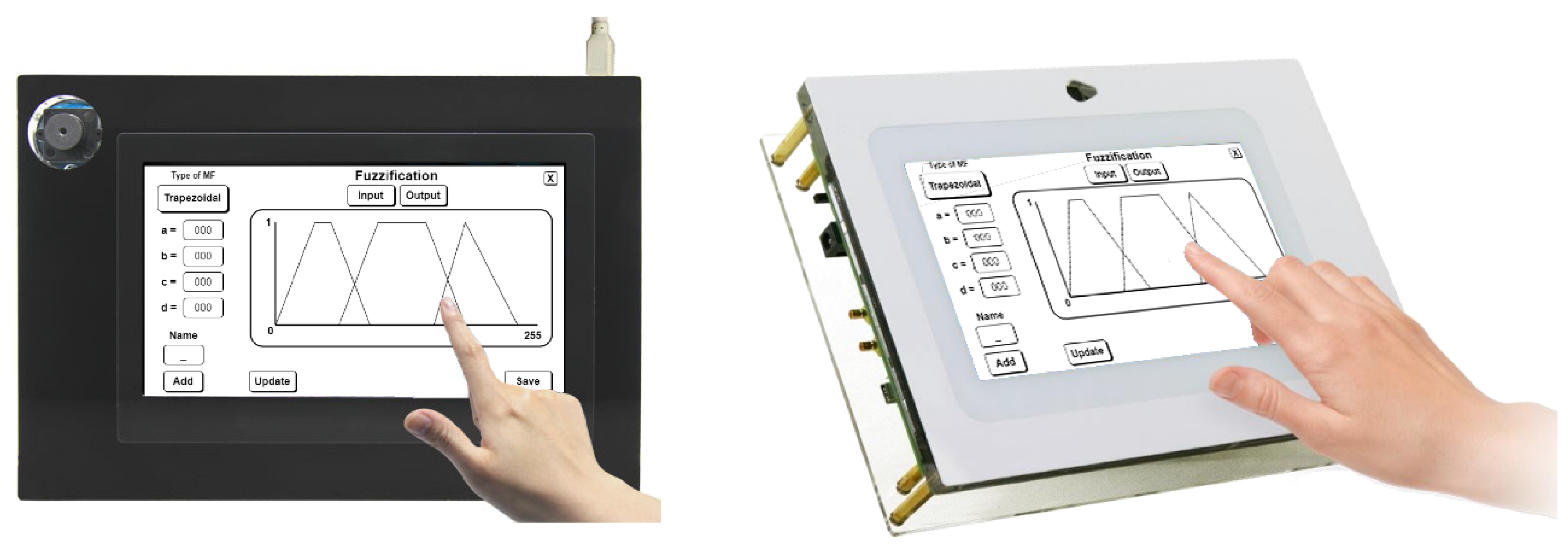
The FIS is compatible with both SoCs because the VHDL code and the GUI were designed to use in SoCs with similar resources, as shown in
Figure 15, where the left is the VEEK-MT and the right is the VEEK-MT2.
The features of the two SoCs are shown in
Table 2. The VEEK-MT2 is one generation newer than VEEK-MT. The RAM memory has been increased from 128 MB to 1024 MB, although the screen size is the same on both SoCs. Finally, the clock is 2× faster than VEEK-MT; the VEEK-MT2 SoC has more capacities because it is the newer generation. Other important resources in the SoC are logic elements, registers, pins, memory, and Phase-Locked Loop (PLL). For example, the logic elements express how the percent of the FPGA is used and total pins represent the inputs and outputs used to implement the design.
5.2. Description of Problem
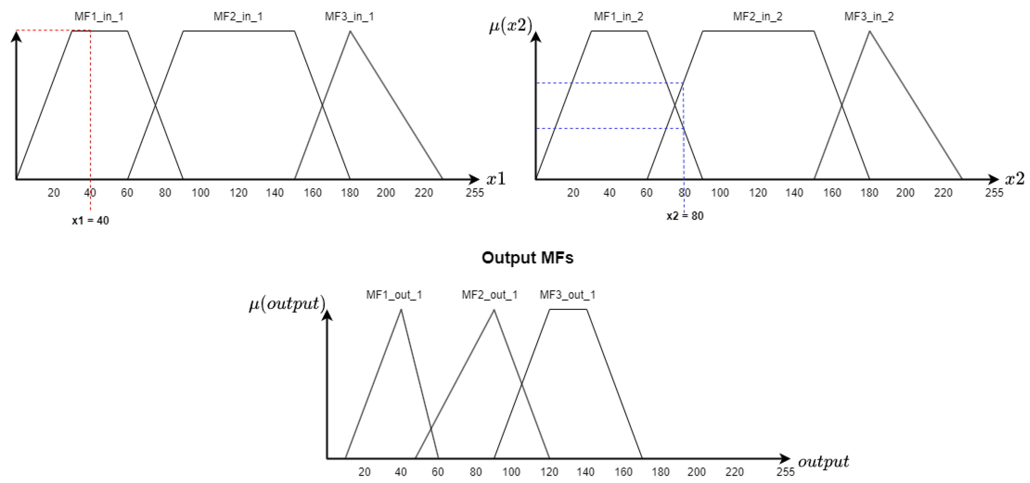
For the experiment, an FIS was proposed with the following characteristics: three MFs (two trapezoidal MFs and one triangular MF) for each input and three MFs (two triangular MFs and one trapezoidal MF) output. The parameters of the MFs are in
Table 3 and the MFs are shown in
Figure 16. The FIS also has three fuzzy rules, as shown in Equation (
6); and finally, to compute the crisp, the input values are x1 = 40 and x2 = 80.
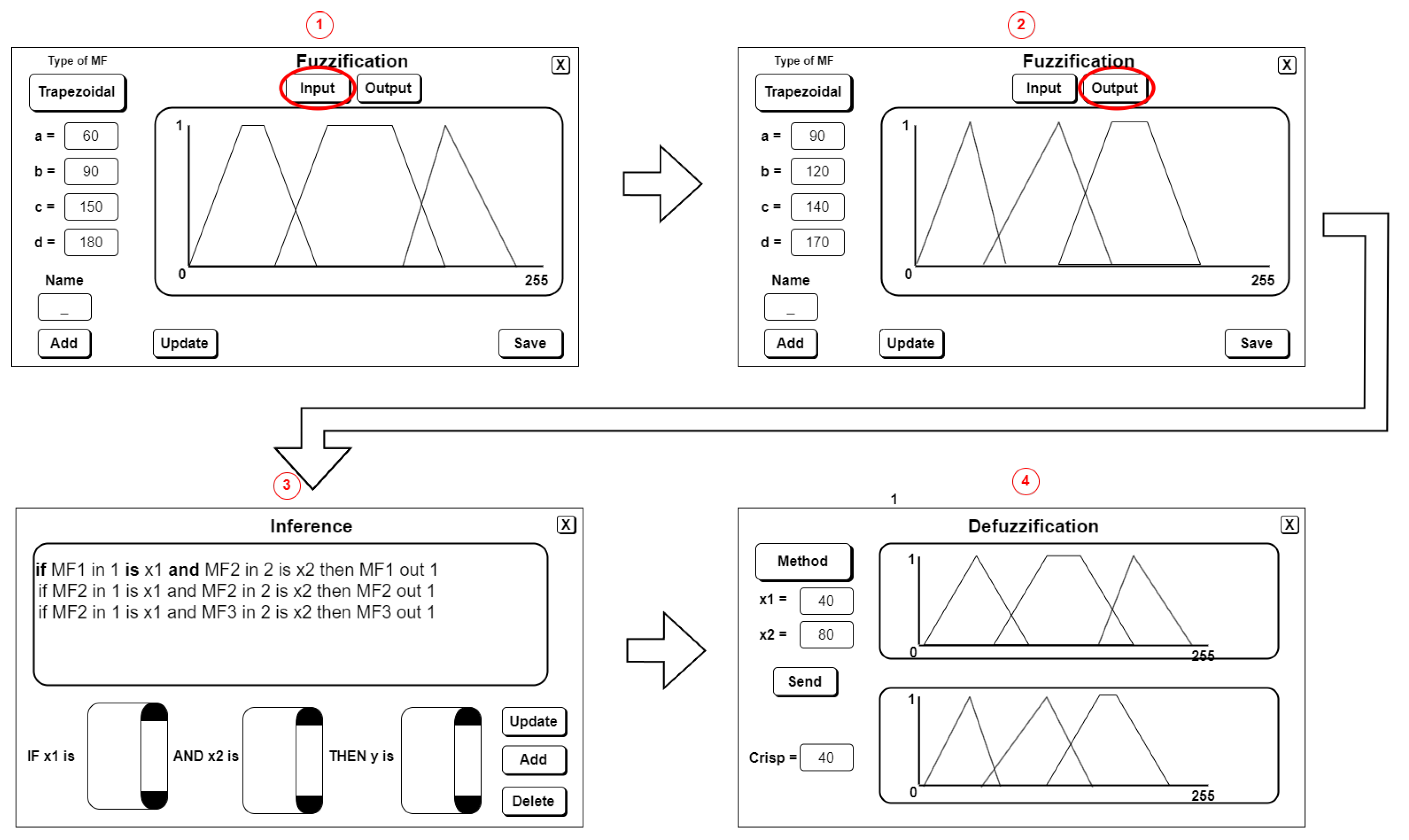
5.3. Experimentation Procedure
To carry out the experiments on the two SoCs, the
Fuzzy Hardware Tool was loaded into the VEEK-MT and VEEK-MT2. The characteristics of the SoCs are presented in
Table 2. Once the
Fuzzy Hardware Tool was loaded, the input MFs were entered on the Fuzzification screen, with three input MFs and three output MFs set as shown in part two of
Figure 17. Continuing with the process, the experiment rules were input on the Inference screen, resulting in the configuration shown in part three of
Figure 17. This experiment consisted of three rules. Finally, on the Defuzzification screen, the process was continued by selecting the values of x1 and x2. The Defuzzification method was also selected to obtain the FIS output, as shown in part four of
Figure 17.
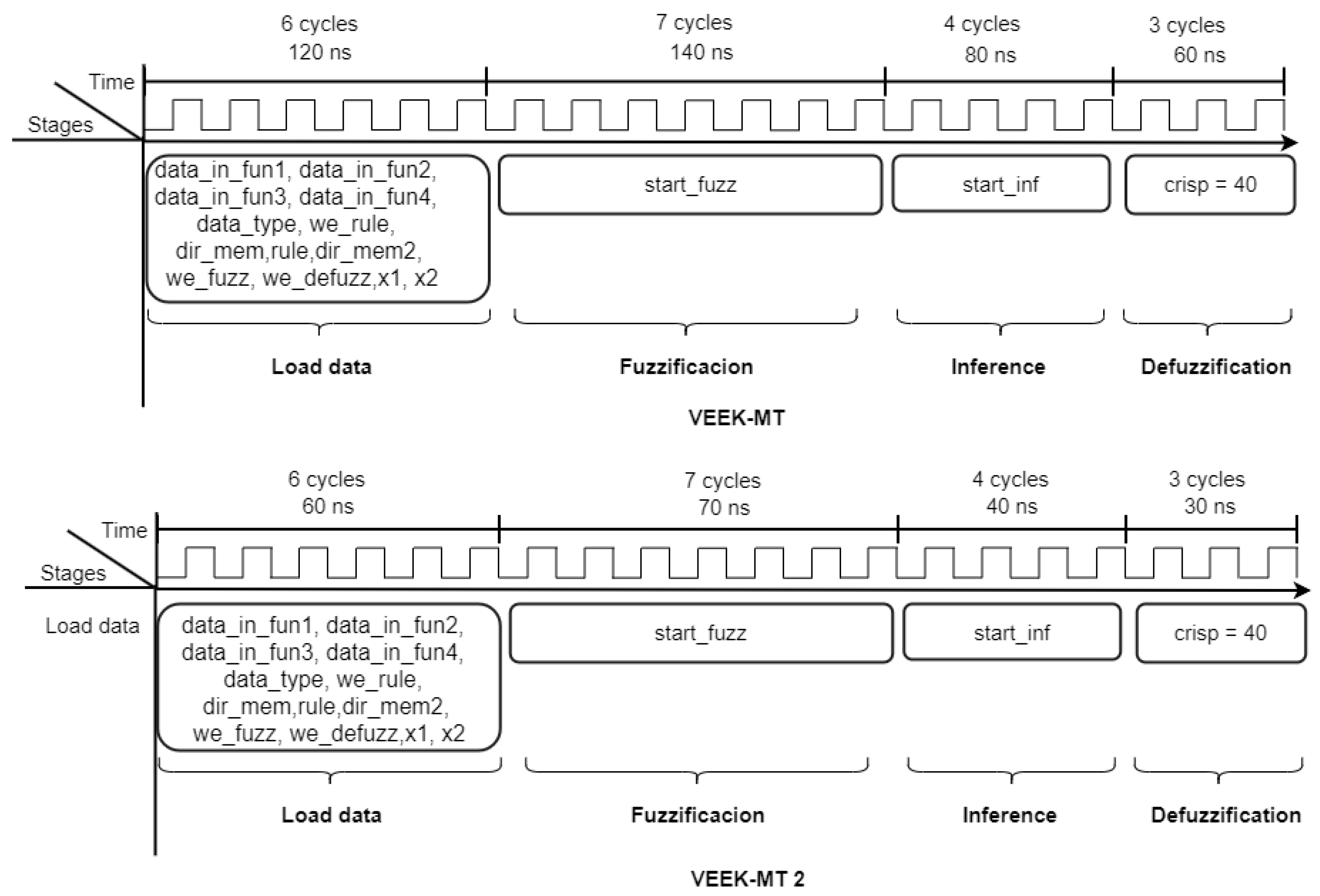
5.4. Experimental Results
After completing the process using the
Fuzzy Hardware Tool, the simulation was performed on the VEEK-MT and VEEK-MT2 SoCs.
Figure 18 illustrates the timing of the FIS and the number of clock cycles required for each step. In this case, the FIS takes six cycles to capture the data, seven cycles for the fuzzification stage, then four cycles for the inference stage, and finally three cycles for the defuzzification stage. The figure also shows that the crisp is calculated at 400 nS for VEEK-MT and 200 nS for VEEK-MT2, due to the clock oscillators of each SoC (see
Table 2).
Once the simulation was finished, the consumption of resources was analyzed, resources estimation are presented in
Table 4. The difference between the two SoCs are that the VEEK-MT has many components such as VGA, LEDs, and display, but the VEEK-MT2 does not have that activated. Finally, the FIS uses two PLLs, which means 50% for VEEK-MT and 25% for the VEEK-MT2. The VEEK-MT2 SoC used 13,832 registers of a total of 166,036, which represents an estimate of 8.3%, while the VEEK-MT SoC used 9562 registers; however, the total number of registers was not found in the SoC documentation.
The results obtained are encouraging becauses the Fuzzy Hardware Tool does not consume even 50% of the resources of the most modern SoC, which allows us to consider adding other implication functions and Defuzzification methods.
The results obtained using the Fuzzy Hardware Tool represent a promising solution for FISs based in hardware. Unlike existing FIS systems that need to be reconfigured each time when the problem changes, the Fuzzy Hardware Tool can be used with different problems without needing to be reloaded or reconfigured. This makes it a highly flexible and efficient option for implementing FISs in hardware.
6. Performance Comparison and Discussion
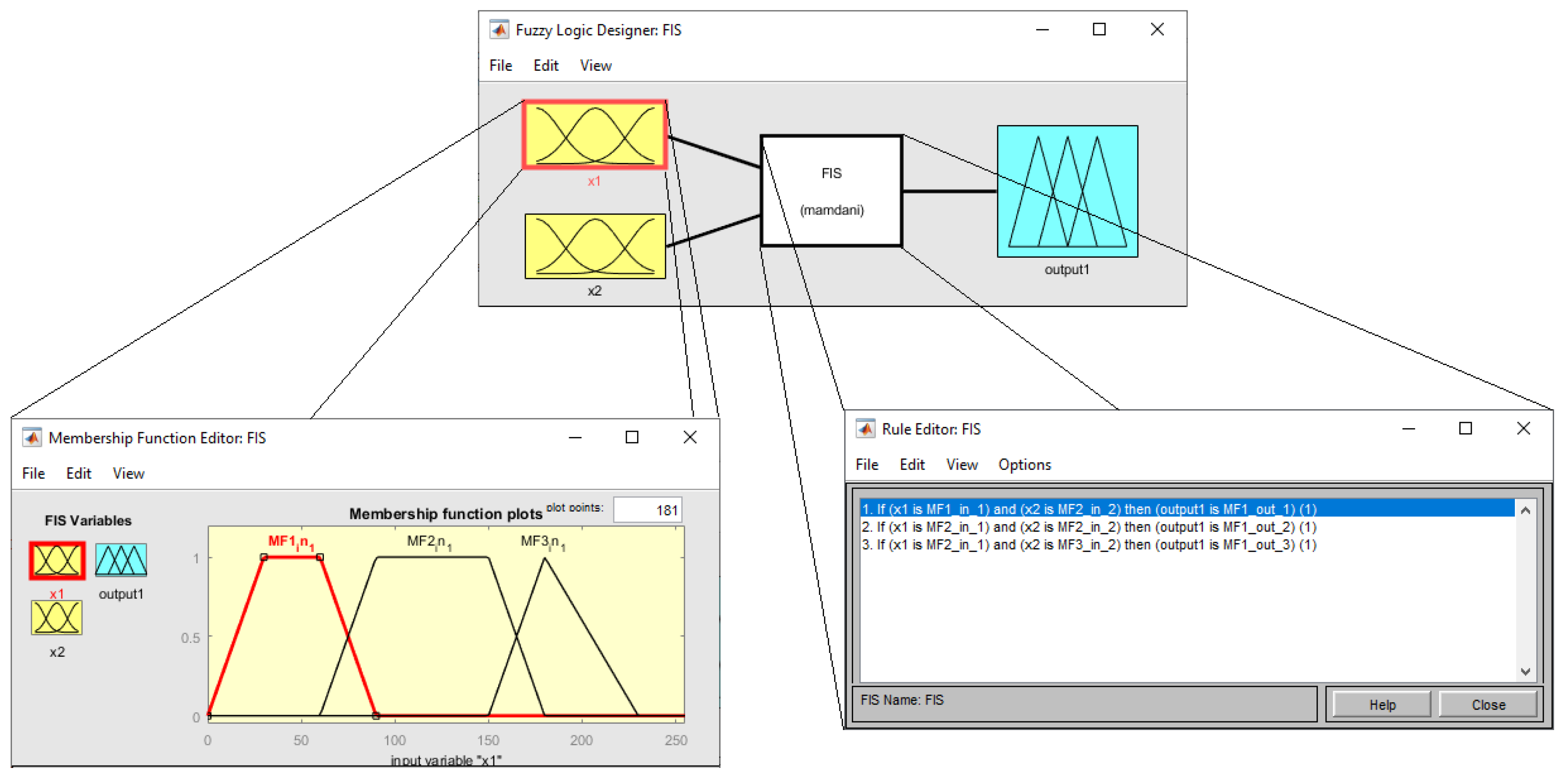
This section offers a comparative study of the results obtained with state of the art tools, such as the
Fuzzy Logic Toolbox [
18], FISDeT [
13], and JUZZY Online [
17]. To do this comparison, the new FIS was designed using the same parameters that the experiment used in
Table 3.
Figure 19 shows the FIS configuration in MATLAB. First, it shows that the FIS has two inputs and one output; next, the characteristics of the membership functions are shown; and finally the fuzzy rules. The centroid is used to calculate the defuzzification instead of the COH method because MATLAB does not have this method in the toolbox.
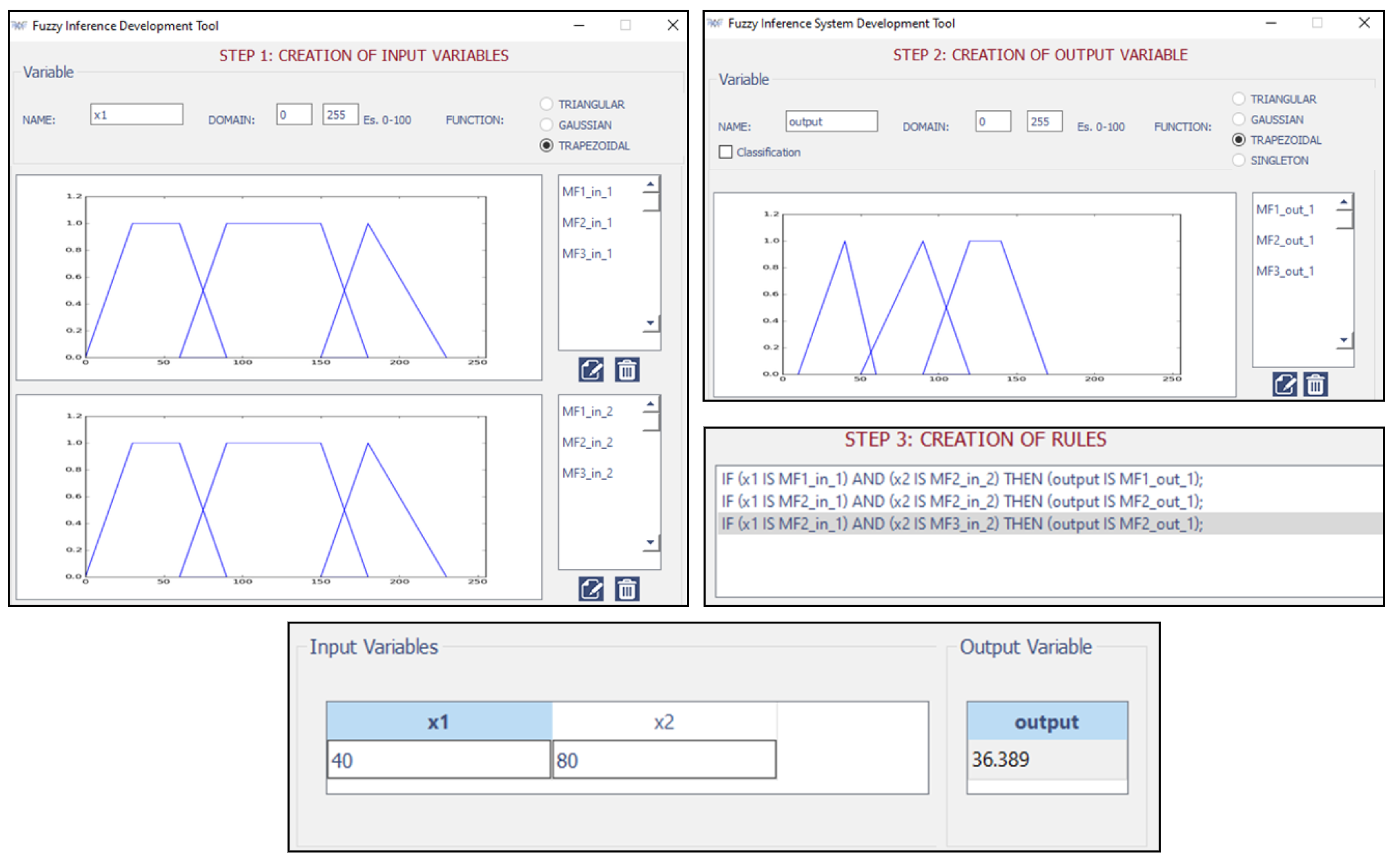
Figure 20 shows the FIS configuration in FISDeT tool. The difference of this FIS with respect to
Figure 19 is the defuzzification method. FISDeT uses the COG method.
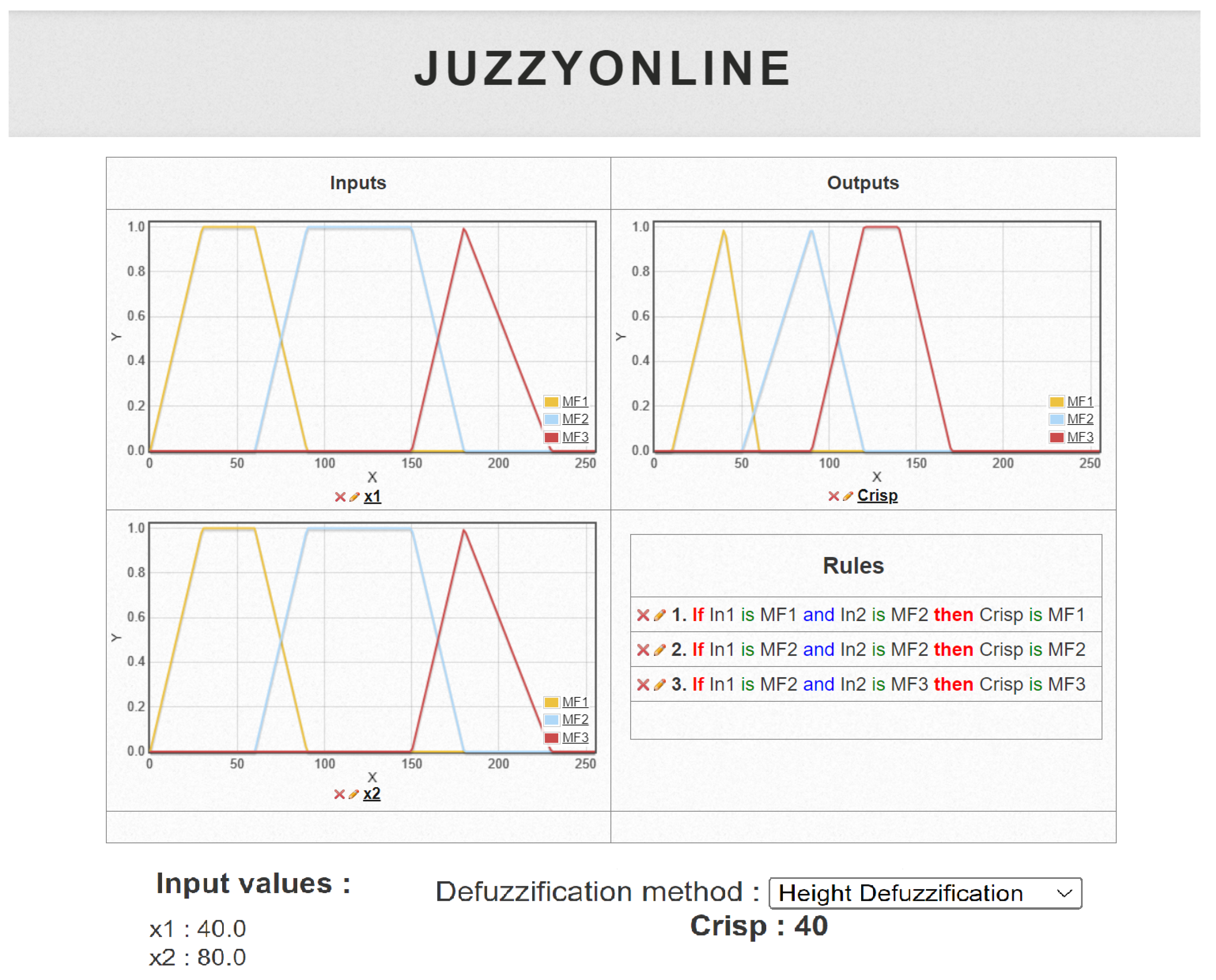
Figure 21 shows the FIS configuration in JUZZY Online tool, which has the same COH defuzzification method as the
Fuzzy Hardware Tool.
Table 5 shows the comparative results between four tools for FIS design, three in software, and the other in hardware. It is important to note that the crisp value of the
Fuzzy Hardware Tool and JUZZY Online are the same because the tools use the same inference and defuzzification methods, while the other two tools use other defuzzification methods such as COG and centroid; therefore, the crisp value is different. Hence, we can mention that the differences in the results occur for the following factors: (1) different defuzzification methods and (2) quantization of the data. The
Fuzzy Hardware Tool is 8-bit quantized.
According to the results obtained, the Fuzzy Hardware Tool has the following advantages: (1) it is the first tool developed on a SoC with a GUI for FIS, with the ability to be adapted to different problems without the need for reprogramming in VHDL or other HDL; (2) the tool leverages the strengths of SoCs, such as their speed; (3) furthermore, the Fuzzy Hardware Tool is an all-in-one tool that can be used without a computer to design and resolve FIS; and (4) the tool can be used by anyone without knowledge about SoCs, only requiring basic knowledge about fuzzy design. Therefore, it makes it an attractive tool for beginners and advanced users.
However, some limitations of the Fuzzy Hardware Tool should be noted. The tool is limited to only two inputs, namely, x1 and x2. In addition, only supports trapezoidal and triangular membership functions. Finally, the tool is limited to problems of 8 bits.
The results obtained using the Fuzzy Hardware Tool represent a promising solution for FIS based in hardware. Unlike existing FIS systems that need to be reconfigured each time when the problem changes, the Fuzzy Hardware Tool can be used with different problems without needing to be reloaded or reconfigured. This makes it a highly flexible and efficient option for implementing FIS in hardware.
7. Conclusions
In this work, we present the
Fuzzy Hardware Tool, a user-friendly tool for designing Fuzzy Inference Systems (FISs) in hardware. The tool consists of two main components: a user interface for designing the FIS and a VHDL code for the underlying process. The user interface allows users to interact with the tool, designing the FIS without the need for expertise in digital system design or FPGA programming. The VHDL code, which is divided into Fuzzification, Inference, and Defuzzification stages, runs the principal process of the FIS when it is loaded by the user. Although there are limitations in this work, as mentioned in
Section 4 and
Section 6, such as the number of inputs and outputs and the types of membership functions supported, the adaptability of the tool still offers advantages, such as intuitive and easy interaction with the fuzzy system through the GUI, which allows the user to implement their system on an FPGA without a deep understanding of VHDL. Moreover, because the code is already synthesized on the FPGA, a computer is not needed, users can make modifications to membership functions, inference rules, and other system components without the requirement to re-synthesize the code. As a result, rapid prototyping and experimentation become possible, greatly facilitating the design process.
In addition, fuzzy systems have found applications in various domains, such as traffic control [
38], energy and irrigation systems [
39], and temperature and humidity control [
40]. These applications sometimes involve the use of fuzzy systems with two inputs, one output, and trapezoidal and triangular membership functions. The proposed tool in this work is capable of accommodating such systems, making it an ideal platform for their implementation on FPGA. This offers users the opportunity to leverage the benefits of these specific fuzzy system characteristics in hardware-based implementations.
The tool was tested through simulations on two SoCs (VEEK-MT and VEEK-MT2) and demonstrated satisfactory results. In conclusion, the Fuzzy Hardware Tool is an innovative solution for utilizing FPGAs in solving FIS problems, making it accessible to individuals without previous knowledge of SoCs or embedded systems, taking advantage of its features. The FIS VHDL code can be implemented on any FPGA regardless of manufacturer, considering a priori the amount of device resources, while the GUI is designed only for VEEK-MT SoCs.
As part of our future work, we plan to expand the capabilities of Fuzzy Hardware Tool by incorporating additional types of membership functions. Furthermore, we intend to explore different implication functions, including max and product, to improve the rule inference process. Additionally, we aim to incorporate the centroid defuzzification method to provide an alternative option for obtaining crisp outputs.
Moreover, we are keen to explore alternative paths for hardware implementation of our FIS, such as utilizing MATLAB/Simulink and the Xfuzzy environment. This investigation will allow us to assess and compare the benefits of each approach in terms of cost, performance, and flexibility. By doing so, we can gain valuable insights into the strengths and limitations of different implementation strategies.
Author Contributions
Conceptualization, R.V., Y.M. and J.A.Q.; methodology, R.V., Y.M. and J.A.Q.; software, R.V., Y.M. and J.A.Q.; validation, R.V., Y.M. and J.A.Q.; formal analysis, R.V., Y.M. and J.A.Q.; investigation, R.V., Y.M. and J.A.Q.; resources, R.V., Y.M. and J.A.Q.; writing—original draft preparation, R.V., Y.M. and J.A.Q.; writing—review and editing, R.V., Y.M. and J.A.Q.; visualization, R.V., Y.M. and J.A.Q.; supervision, Y.M.; project administration, Y.M.; funding acquisition, Y.M. All authors have read and agreed to the published version of the manuscript.
Funding
This research was supported by TecNM (Mexico) project 17615.23-P and the first, and third author were supported by CONAHCYT scholarships 692786 and 1014860, respectively.
Data Availability Statement
Not applicable.
Conflicts of Interest
The authors declare no conflict of interest.
References
- Zadeth, L. Fuzzy sets. Inf. Control 1965, 8, 338–353. [Google Scholar] [CrossRef]
- Zavala, A.; Nieto, O. Fuzzy hardware: A retrospective and analysis. IEEE Trans. Fuzzy Syst. 2011, 20, 623–635. [Google Scholar] [CrossRef]
- Li, H.; Wu, C.; Shi, P.; Gao, Y. Control of nonlinear networked systems with packet dropouts: Interval type-2 fuzzy model-based approach. IEEE Trans. Cybern. 2014, 45, 2378–2389. [Google Scholar] [CrossRef]
- Gacto, M.J.; Galende, M.; Alcalá, R.; Herrera, F. METSK-HDe: A multiobjective evolutionary algorithm to learn accurate TSK-fuzzy systems in high-dimensional and large-scale regression problems. Inf. Sci. 2014, 276, 63–79. [Google Scholar] [CrossRef]
- Ishibuchi, H.; Mihara, S.; Nojima, Y. Parallel distributed hybrid fuzzy GBML models with rule set migration and training data rotation. IEEE Trans. Fuzzy Syst. 2012, 21, 355–368. [Google Scholar] [CrossRef]
- Narayan, V.; Mall, P.K.; Awasthi, S.; Srivastava, S.; Gupta, A. FuzzyNet: Medical Image Classification based on GLCM Texture Feature. In Proceedings of the 2023 International Conference on Artificial Intelligence and Smart Communication (AISC), Greater Noida, India, 27–29 January 2023; pp. 769–773. [Google Scholar]
- Nassiri, S.M.; Tahavoor, A.; Jafari, A. Fuzzy logic classification of mature tomatoes based on physical properties fusion. Inf. Process. Agric. 2022, 9, 547–555. [Google Scholar] [CrossRef]
- Hannan, M.A.; Ghani, Z.A.; Hoque, M.M.; Ker, P.J.; Hussain, A.; Mohamed, A. Fuzzy logic inverter controller in photovoltaic applications: Issues and recommendations. IEEE Access 2019, 7, 24934–24955. [Google Scholar] [CrossRef]
- Rahman, M.Z.; Akbar, M.A.; Leiva, V.; Tahir, A.; Riaz, M.T.; Martin-Barreiro, C. An intelligent health monitoring and diagnosis system based on the internet of things and fuzzy logic for cardiac arrhythmia COVID-19 patients. Comput. Biol. Med. 2023, 154, 106583. [Google Scholar] [CrossRef]
- Jan, N.; Gwak, J.; Pamucar, D. Mathematical analysis of generative adversarial networks based on complex picture fuzzy soft information. Appl. Soft Comput. 2023, 137, 110088. [Google Scholar] [CrossRef]
- Jan, N.; Gwak, J.; Maqsood, R.; Nasir, A. Analysis of Networks and Digital Systems by Using the Novel Technique Based on Complex Fuzzy Soft Information. IEEE Trans. Consum. Electron. 2022, 69, 183–193. [Google Scholar] [CrossRef]
- Gwak, J.; Garg, H.; Jan, N. Investigation of robotics technology based on bipolar complex intuitionistic fuzzy soft relation. Int. J. Fuzzy Syst. 2023, 25, 1834–1852. [Google Scholar] [CrossRef]
- Castellano, G.; Castiello, C.; Pasquadibisceglie, V.; Zaza, G. Fisdet: Fuzzy inference system development tool. Int. J. Comput. Intell. Syst. 2017, 10, 13–22. [Google Scholar] [CrossRef]
- McCulloch, J. Fuzzycreator: A python-based toolkit for automatically generating and analysing data-driven fuzzy sets. In Proceedings of the 2017 IEEE International Conference on Fuzzy Systems (FUZZ—IEEE), Naples, Italy, 9–12 July 2017; pp. 1–6. [Google Scholar]
- Guillaume, S.; Charnomordic, B. Fuzzy inference systems: An integrated modeling environment for collaboration between expert knowledge and data using FisPro. Expert Syst. Appl. 2012, 39, 8744–8755. [Google Scholar] [CrossRef]
- Cingolani, P.; Alcalá-Fdez, J. jFuzzyLogic: A java library to design fuzzy logic controllers according to the standard for fuzzy control programming. Int. J. Comput. Intell. Syst. 2013, 6, 61–75. [Google Scholar] [CrossRef]
- Wagner, C.; Pierfitt, M.; McCulloch, J. Juzzy online: An online toolkit for the design, implementation, execution and sharing of type-1 and type-2 fuzzy logic systems. In Proceedings of the 2014 IEEE International Conference on Fuzzy Systems (FUZZ-IEEE), Beijing, China, 6–11 July 2014; pp. 2321–2328. [Google Scholar]
- The MathWorks, Inc. Matlab Fuzzy Logic Tool Users Guide. 2022. Available online: https://www.mathworks.com/help/fuzzy/ (accessed on 5 May 2023).
- Sharma, S.; Obaid, A.J. Mathematical modelling, analysis and design of fuzzy logic controller for the control of ventilation systems using Matlab fuzzy logic toolbox. J. Interdiscip. Math. 2020, 23, 843–849. [Google Scholar] [CrossRef]
- Dagar, P.; Jatain, A.; Gaur, D. Medical diagnosis system using fuzzy logic toolbox. In Proceedings of the International Conference on Computing, Communication & Automation, Greater Noida, India, 15–16 May 2015; pp. 193–197. [Google Scholar]
- Elias, N.; Yahya, N.M.; Sing, E.H. Numerical analysis of fuzzy logic temperature and humidity control system in pharmaceutical warehouse using Matlab fuzzy toolbox. In Proceedings of the Intelligent Manufacturing & Mechatronics, Pekan, Malaysia, 29 January 2018; pp. 623–629. [Google Scholar]
- Taskin, A.; Kumbasar, T. An open source Matlab/Simulink toolbox for interval type-2 fuzzy logic systems. In Proceedings of the 2015 IEEE Symposium Series On Computational Intelligence, Cape Town, South Africa, 7–10 December 2015; pp. 1561–1568. [Google Scholar]
- Alcalá-Fdez, J.; Alonso, J.M. A survey of fuzzy systems software: Taxonomy, current research trends, and prospects. IEEE Trans. Fuzzy Syst. 2015, 24, 40–56. [Google Scholar] [CrossRef]
- Costa, A.; de Gloria, A.; Faraboschi, P.; Pagni, A.; Rizzotto, G. Hardware solutions for fuzzy control. Proc. IEEE 1995, 83, 422–434. [Google Scholar] [CrossRef]
- Hollstein, T.; Halgamuge, S.; Glesner, M. Computer-aided design of fuzzy systems based on generic VHDL specifications. IEEE Trans. Fuzzy Syst. 1996, 4, 403–417. [Google Scholar] [CrossRef]
- López, D.; Jiménez, C.; Baturone, I.; Barriga, A.; Sánchez-Solano, S. Xfuzzy: A design environment for fuzzy systems. In Proceedings of the 1998 IEEE International Conference on Fuzzy Systems Proceedings. IEEE World Congress On Computational Intelligence, Anchorage, AL, USA, 4–9 May 1998; Volume 2, pp. 1060–1065. [Google Scholar]
- Montesino Pouzols, F.; Barriga Barros, Á.; Lopez, D.; Sánchez Solano, S. Open FPGA-based development platform for fuzzy systems with applications to communications. In Proceedings of the XXII Conference on Design of Circuits and Integrated Systems, Rio de Janeiro, Brazil, 3–6 September 2007; pp. 1–6. [Google Scholar]
- Brox, M.; Sánchez-Solano, S.; Toro, E.; Brox, P.; Moreno-Velo, F. CAD tools for hardware implementation of embedded fuzzy systems on FPGAs. IEEE Trans. Ind. Inform. 2012, 9, 1635–1644. [Google Scholar] [CrossRef]
- Mamdani, E.; Assilian, S. An experiment in linguistic synthesis with a fuzzy logic controller. Int. J.-Man-Mach. Stud. 1975, 7, 1–13. [Google Scholar] [CrossRef]
- Ross, T. Fuzzy Logic with Engineering Applications; John Wiley & Sons: Hoboken, NJ, USA, 2005. [Google Scholar]
- Huang, H.; Xu, H.; Chen, F.; Zhang, C.; Mohammadzadeh, A. An Applied Type-3 Fuzzy Logic System: Practical Matlab Simulink and M-Files for Robotic, Control, and Modeling Applications. Symmetry 2023, 15, 475. [Google Scholar] [CrossRef]
- Ilyas, A.; Khan, M.R.; Ayyub, M. FPGA based real-time implementation of fuzzy logic controller for maximum power point tracking of solar photovoltaic system. Optik 2020, 213, 164668. [Google Scholar] [CrossRef]
- Prabakaran, G.; Vaithiyanathan, D.; Ganesan, M. FPGA based intelligent embedded system for predicting the productivity using fuzzy logic. Sustain. Comput. Inform. Syst. 2022, 35, 100749. [Google Scholar] [CrossRef]
- Moreno Velo, F.; Sánchez Solano, S.; Barriga Barros, Á.; Baturone Castillo, M.; López, D. Xfl3: A new fuzzy system specification language. In Proceedings of the 5th WSES /IEEE Multiconference on Circuits, Systems, Communications And Computers, Rethymnon, Greece, 8–15 July 2001; pp. 361–366. [Google Scholar]
- Velo, F.; Baturone, L.; Solano, S.; Barriga, A. Rapid design of fuzzy systems with Xfuzzy. In Proceedings of the 12th IEEE International Conference On Fuzzy Systems, St. Louis, MO, USA, 25–28 May 2003; Volume 1, pp. 342–347. [Google Scholar]
- Mohammadi, M.; Shaout, A. Reconfigurable implementation of fuzzy inference system using FPGA. In Proceedings of the 2017 International Conference On New Trends In Computing Sciences (ICTCS), Amman, Jordan, 11–13 October 2017; pp. 18–23. [Google Scholar]
- Terasic Inc. Video and Embedded Evaluation Kit—Multi-Touch. 2022. Available online: https://www.terasic.com (accessed on 5 May 2023).
- Alam, J.; Pandey, M.K. Design and analysis of a two stage traffic light system using fuzzy logic. J. Inf. Technol. Softw. Eng. 2015, 5, 162. [Google Scholar] [CrossRef]
- Munir, M.S.; Bajwa, I.S.; Naeem, M.A.; Ramzan, B. Design and implementation of an IoT system for smart energy consumption and smart irrigation in tunnel farming. Energies 2018, 11, 3427. [Google Scholar] [CrossRef]
- Furizal, F.; Sunardi, S.; Yudhana, A. Temperature and Humidity Control System with Air Conditioner Based on Fuzzy Logic and Internet of Things. J. Robot. Control 2023, 4, 308–322. [Google Scholar]
Figure 1.
(a) Triangular membership function and (b) trapezoidal membership function.
Figure 1.
(a) Triangular membership function and (b) trapezoidal membership function.
Figure 2.
Basic diagram for the Fuzzy Hardware Tool with the three main stages.
Figure 2.
Basic diagram for the Fuzzy Hardware Tool with the three main stages.
Figure 3.
Bus func divided into four variables of 8 bits to receive MFs of the GUI.
Figure 3.
Bus func divided into four variables of 8 bits to receive MFs of the GUI.
Figure 4.
Bus vars divided into nine variables of different bits.
Figure 4.
Bus vars divided into nine variables of different bits.
Figure 5.
Bus reg_mem divided in two variables of different bits.
Figure 5.
Bus reg_mem divided in two variables of different bits.
Figure 6.
Bus output has one variable with 8 bits and one empty variable with 24 bits.
Figure 6.
Bus output has one variable with 8 bits and one empty variable with 24 bits.
Figure 7.
Diagram of Fuzzification stage for two linguistic variables (x1 and x2) and up to 15 triangular and trapezoidal MFs.
Figure 7.
Diagram of Fuzzification stage for two linguistic variables (x1 and x2) and up to 15 triangular and trapezoidal MFs.
Figure 8.
Diagram of the control process to the Inference stage.
Figure 8.
Diagram of the control process to the Inference stage.
Figure 9.
UML of the process into the GUI.
Figure 9.
UML of the process into the GUI.
Figure 10.
First and second screen of the GUI.
Figure 10.
First and second screen of the GUI.
Figure 11.
Fuzzification screen with nine options.
Figure 11.
Fuzzification screen with nine options.
Figure 12.
Keyboards for the GUI used to capture the name of the MFs.
Figure 12.
Keyboards for the GUI used to capture the name of the MFs.
Figure 13.
Inference screen with their 6 options.
Figure 13.
Inference screen with their 6 options.
Figure 14.
Defuzzification screen with their 5 options.
Figure 14.
Defuzzification screen with their 5 options.
Figure 15.
VEEK-MT and VEEK-MT2, respectively, with Fuzzy Hardware Tool loaded.
Figure 15.
VEEK-MT and VEEK-MT2, respectively, with Fuzzy Hardware Tool loaded.
Figure 16.
Graphical representation of the MFs of the input x1 and x2 and output.
Figure 16.
Graphical representation of the MFs of the input x1 and x2 and output.
Figure 17.
Process of the experiment with Fuzzy Hardware Tool.
Figure 17.
Process of the experiment with Fuzzy Hardware Tool.
Figure 18.
Simulation of the FIS in the Fuzzy Hardware Tool for the VEEK-MT and VEEK-MT2 SoCs.
Figure 18.
Simulation of the FIS in the Fuzzy Hardware Tool for the VEEK-MT and VEEK-MT2 SoCs.
Figure 19.
Design of the FIS in MATLAB using
Fuzzy Logic Toolbox [
18].
Figure 19.
Design of the FIS in MATLAB using
Fuzzy Logic Toolbox [
18].
Figure 20.
Design steps for FIS implementation using FISDeT [
13].
Figure 20.
Design steps for FIS implementation using FISDeT [
13].
Figure 21.
FIS design using JUZZY Online [
17].
Figure 21.
FIS design using JUZZY Online [
17].
Table 1.
Comparison of fuzzy logic tools by features as GUI, support for hardware implementation, and additional notes.
Table 1.
Comparison of fuzzy logic tools by features as GUI, support for hardware implementation, and additional notes.
| Tool Name | GUI | Support Hardware | Additional Notes |
|---|
| FISDeT [13] | ✓ | - | - |
| FisPro [15] | ✓ | - | - |
| jFuzzyLogic [16] | ✓ | - | - |
| fuzzycreator [14] | - | - | Supports T1 and IT2 FIS |
| JUZZY Online [17] | ✓ | - | Online application |
| MATLAB/Simulink [18] | ✓ | ✓ | Includes Fuzzy Logic Toolbox and XSG in its environment |
| Xfuzzy [34,35] | ✓ | ✓ | Implements XFL3 specification language |
| Fuzzy Hardware Tool | ✓ | ✓ | Configurable through touchscreen GUI |
Table 2.
Features of VEEK-MT and VEEK-MT2 SoCs.
Table 2.
Features of VEEK-MT and VEEK-MT2 SoCs.
| Features | VEEK-MT | VEEK-MT2 |
|---|
| Processor | NIOS II | NIOS II |
| FPGA | Cyclone IV E | Cyclone V SX |
| Device | EP4CE115F29C7 | 5CSXFC6D6F31C6 |
| Clock rate | 50 MHz | 100 MHz |
| Time period | 20 nS | 10 nS |
| RAM | 128 MB SDRAM | 1024 MB DDR3 |
| Screen | 7 inches LCD | 7 inches LCD |
Table 3.
MFs parameters of the experiment.
Table 3.
MFs parameters of the experiment.
| Linguistic Term | Linguistic Variable | Linguistic Term | Linguistic Variable |
|---|
| x1 | x2 | Output |
|---|
MF1_in_1
MF1_in_2 | a = 0 | a = 0 | MF1_out_1 | a = 10 |
| b = 30 | b = 30 | b = 40 |
| c = 60 | c = 60 | c = 60 |
| d = 90 | d = 90 | |
MF2_in_1
MF2_in_2 | a = 60 | a = 60 | MF2_out_1 | a = 50 |
| b = 90 | b = 90 | b = 90 |
| c = 150 | c = 150 | c = 120 |
| d = 180 | d = 180 | |
MF3_in_1
MF3_in_2 | a = 150 | a = 150 | MF3_out_1 | a = 90 |
| b = 180 | b = 180 | b = 120 |
| c = 230 | c = 230 | c = 140 |
| | | d = 170 |
Table 4.
Resources utilization of two SoCs with the Fuzzy Hardware Tool.
Table 4.
Resources utilization of two SoCs with the Fuzzy Hardware Tool.
| Resource | VEEK-MT | VEEK-MT2 |
|---|
| Logic elements | 12% | 18% |
| Total pins | 90% | 41% |
| Total memory bits | 3% | 16% |
| Total PLLs | 50% | 25% |
Table 5.
FIS comparison using Fuzzy Hardware Tool, Fuzzy Logic Toolbox, FISDeT, and JUZZY Online.
Table 5.
FIS comparison using Fuzzy Hardware Tool, Fuzzy Logic Toolbox, FISDeT, and JUZZY Online.
| | Fuzzy Hardware Tool | Fuzzy Logic Toolbox [18] | FISDeT [13] | JUZZY Online [17] |
|---|
| Inputs values | x1 = 40, x2 = 80 | x1 = 40, x2 = 80 | x1 = 40, x2 = 80 | x1 = 40, x2 = 80 |
| Implication | min | min | min | min |
| Defuzzification | COH | Centroid | COG | COH |
| Crisp | 40 | 36.4 | 36.3 | 40 |
| Disclaimer/Publisher’s Note: The statements, opinions and data contained in all publications are solely those of the individual author(s) and contributor(s) and not of MDPI and/or the editor(s). MDPI and/or the editor(s) disclaim responsibility for any injury to people or property resulting from any ideas, methods, instructions or products referred to in the content. |
© 2023 by the authors. Licensee MDPI, Basel, Switzerland. This article is an open access article distributed under the terms and conditions of the Creative Commons Attribution (CC BY) license (https://creativecommons.org/licenses/by/4.0/).


