Abstract
In order to properly cover different scenarios, radiation patterns of antennas should be accordingly designed. However, most antennas are unable to provide either broadside beams or designable conical beams, which are the typically used radiation patterns for radio coverage, based on one single-structure format through adjusting parameters before fabrication. In this paper, a planar circular polarized (CP) annular leaky-wave antenna (LWA) is proposed, which is realized on an annular substrate-integrated waveguide (SIW). A broadside beam or a conical beam could be easily obtained through fabricating the LWA with different structural parameters. The operating frequency is 5.75 GHz. The LWA allows only the −1st spatial harmonic to radiate, while the fundamental wave and other spatial harmonics are suppressed in slow wave mode. In order to validate the design effectiveness, two examples for broadside beam and conical beam radiation are fabricated and measured. The measurement results show good agreement with the simulation results. The broadside beam LWA shows a gain of 9.75 dBic and the conical beam LWA with a beam angle of 13° has a gain of 7.93 dBic. The proposed LWA presents promising radiation performance and is a good candidate for wireless communication applications.
1. Introduction
Circularly polarized (CP) antennas have been studied for a long time due to their advantage of low polarization mismatch loss in applications. Among different kinds of CP antennas, the CP conical beam antenna is one of the important candidates for wireless communication applications. In [1], a low-profile wideband CP conical beam antenna with arc-hook-shaped branches is proposed. In [2], a transmissive metasurface method for generating a conical beam is put forward. In [3], an open-ended coaxial waveguide aperture antenna for conical beam radiation is proposed. In [4], a truncated circular cone slot antenna array with a CP conical beam is designed, whose beam angle can be adjusted through changing the inclining angle of the cone surface. In [5], a modified crossed-wire antenna featuring a wideband conical beam is proposed. In [6], a CP reconfigurable antenna equipped with a switchable feeding network for conical beam and broadside radiation is proposed. In [7], a CP wideband dual-cavity-backed crossed dipole antenna is proposed. In [8], a single-fed dual-slot broadband antenna generating a CP broadside beam is proposed. In [9], a compact dual-band and dual CP stacked patch antenna generating a broadside beam is put forward. In [10], a low-profile wideband circular patch antenna providing a broadside beam and a conical beam is proposed. In [11], a surface wave holographic antenna excited via a fundamental mode patch array for broadside radiation is proposed. However, most antennas are unable to switch between providing a broadside beam and a designable conical beam based on one single structure format but generate only broadside beams or conical beams. Although a few published approaches allow to generate both broadside beams and conical beams with the same structure format, it is difficult to adjust the beam angle of the conical beam during the design process. Thus, it is necessary to put forward new methods of antenna design for supporting the generation of broadside beams or designable conical beams using the same antenna structure format.
Leaky-wave antennas (LWAs) [12], a popular type of antenna characterized by their flexible traveling-wave radiation property, have been researched for decades and are becoming a hot topic today [13,14,15,16]. On the basis of LWA, all kinds of radiation properties have been realized, e.g., linearly polarized (LP) and CP radiation on dual bands [13], wide forward [14] and low loss [15], dual-polarized fixed beam with high isolation and cross-polarization [16], etc. In our previous work, an annular LWA with rectangular slots is proposed [17], which can generate a CP conical beam and a broadside beam.
In this paper, a CP planar annular LWA with circular slots based on an SIW is proposed with the novelty and contribution of (1) using the mono radiation of the −1st harmonic in an annular LWA for more flexible beam adjustment in the design process, (2) arranging deviated CP circular slots in an annular SIW to guarantee CP radiation, and (3) presenting two cases of antennas with a broadside beam and conical beam separately to validate the antenna design method. Through adjusting and optimizing the structure parameters, CP conical beams or broadside beams with higher gain can be obtained. The antenna structure is described in Section 2. Analysis for impedance matching and radiation properties is implemented in Section 3. Antenna validation is presented in Section 4. Conclusions are given in Section 5.
2. Antenna Structure
The structure of the proposed LWA is built using commercial full-wave simulation software and illustrated in Figure 1. It has two layers: the radiating layer and the feeding layer. In the radiating layer, a series of circular slots with constant intervals are etched in the top plane, and the locations of the slots are deviated away from the middle axis of the annular SIW. In the feeding layer, two arc-shaped feeding cavities proposed in previous work [17] are used. Two slots are etched in the bottom plane of the radiating SIW layer (also the top plane of the feeding layer) for coupling energy from the feeding layer to the radiating layer. To excite the cavities, two coaxial probes are welded at the bottom of the feeding layer, one for feeding energy into the LWA, and the other is terminated with a 50 Ohm matched load for absorbing the rest power. Both of the layers are designed on F4BM-2 substrates with εr = 3.2 (with the tolerance of ±2%) and tanδ ≤ 0.002. The thicknesses of the two layers are both set to 4 mm. The operating frequency of the LWA is set to 5.75 GHz. To assemble the LWA compactly, plastic screws are used.
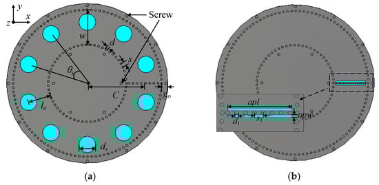
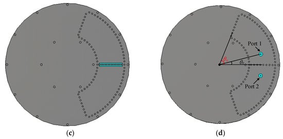
Figure 1.
Structure of the proposed LWA: (a) top view of the radiation layer, (b) back view of the radiation layer, (c) top view of the feeding layer, and (d) back view of the feeding layer.
3. Parameter Analysis
In this section, the impedance and radiation properties are studied and analyzed through a commercial full-wave simulation software, including the changes due to the modification of the parameters of the structure and the underlying principles.
3.1. Optimization of Impedance Matching
In order to achieve impedance matching, a series of variable analyses are carried out. First, the deviation distance of slots away from the middle axis of the SIW doff = w-l0 is studied. When doff = 0, the slots are arranged in the middle axis of the SIW. As stated in [18], the transmission property of an annular SIW is almost identical to that of a straight SIW, and the electric field magnitude along the middle axis is the largest, so in case of doff = 0 the wave travelling in the SIW is strongly perturbed by the slots. This will cause strong reflection in the SIW, and the return loss will be high, as depicted in Figure 2a. To reduce the return loss, a deviation distance of slots away from the middle axis should be set. However, if doff is too large, the slots cannot effectively cut the surface current, and the radiation efficiency will be low. Therefore, doff needs to be adequately considered and determined for low return loss and high radiation efficiency. Second, the diameter of the slots ds is analyzed for impedance matching. Figure 2b shows the variation of return loss with ds. If ds is small, the return loss is low, but the radiation efficiency will be low. If a large ds is chosen, the return loss will increase, obviously. So, ds should also be selected properly. The analysis above is performed based on the proposed LWA fed and terminated via perfect waveguide ports. Practically, an arc-shaped feeding cavity designed in [17], as mentioned in the last section, is used to feed the structure as sketched in Figure 1d. The angle θc is optimized to 70° to guarantee half of the guided wavelength inside the cavities for low return loss at the frequency of interest.
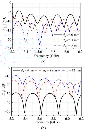
Figure 2.
|S11| of the LWA as function of different variables: (a) doff, (b) ds, w = 27 mm and C = 43.5 mm.
3.2. Analysis of Radiation Property
The working mode in the proposed LWA is TE10, whose electric distribution is illustrated in Figure 3. It can be observed that the wave mode is slightly disturbed due to the existence of deviated circular slots. Only −1st harmonic is allowed to be radiated [19], so the radiation condition of the proposed LWA can be expressed using
where βm is the propagation constant of the mth spatial harmonic, εg denotes the effective dielectric constant of SIW, and p is the arc-length period of slots. Figure 4 depicts the normalized propagation and attenuation constants of the fundamental wave and −1st spatial harmonic in the proposed LWA. It is in Figure 4a that the fundamental wave operates in the slow wave region (β0 > k0) and does not contribute to the radiation field. Radiation is generated by the −1st spatial harmonic because β-1/k0 is in the range of (−1, 1).
Figure 3.
Transient electric field distribution of the proposed LWA. w = 27 mm, C = 43.5 mm, l0 = 17.5 mm, and θs = 36°.
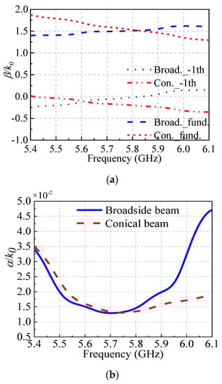
Figure 4.
Dispersion curves of the LWA: (a) phase constant, (b) attenuation constant; θs = 40° and l0 = 16.9 mm for broadside beam, θs = 36° and l0 = 17.5 mm for conical beam, w = 27 mm, and C = 43.5 mm.
As we know, for the radiation of −1st spatial harmonic, different slot intervals lead to different beam angles. To demonstrate the radiation property of the proposed LWA, three examples are given, one for broadside beam radiation (LWA 1) and two for conical beam radiation (LWAs 2 and 3). Figure 5 presents the radiation patterns of the LWAs with different slot intervals, which are listed in Table 1. The normal direction, i.e., the broadside direction of the planar LWA is pointing at +z direction, i.e., θ = 0. The plane in which the LWAs are extended is xoy-plane, i.e., θ = 90°. So, the broadside beam and the middle axial of the conical beam are pointing at θ = 0°. Figure 5a gives the radiation patterns for broadside beams and conical beams with different beam angles in the xoz-plane. Specifically, the omnidirectivity of the conical beams is presented in Figure 5b. Hence, the introduction of LWAs 2 and 3 shows that conical beams with different angles are generated through adjusting the structural parameters. Furthermore, the CP property of the LWA can be explained from two aspects: one is the element CP property, i.e., the slot CP property; the other is the leaky-wave structure CP property. With regard to the slot CP property, the electric distribution of one single slot is demonstrated in Figure 6, and the slot is designed closer to the outer edge of the annular structure (as depicted in Figure 3). It can be seen in Figure 6 that the aperture field on the slot points upwards at the first quarter of one period; then, in the second quarter of the period, the aperture field points in right-hand direction. This means that in a whole period, the direction of the aperture field rotates clockwise over 2π. Two orthogonal electric components y and x with +90° phase difference are excited, so that left-hand circular polarization (LHCP) is generated by a single circular slot. Then, as for the leaky-wave structure CP property, it should be noticed that the LWA is excited from Port 1, and Port 2 is terminated with a 50 Ohm matched load, which means that the wave travelling in the SIW is anticlockwise. In terms of the leaky radiation from an annular travelling wave, a CP property is possible to be generated. According to previous work [17], an antenna working on fundamental mode radiation will generate right-hand circular polarization (RHCP) radiation when excited by an anticlockwise-travelling wave. However, for the −1st spatial harmonic, i.e., m = −1 in Equation (1), the propagation constant is below zero at 5.75 GHz as depicted in Figure 4a, which means the wave phase flows inversely against the wave energy in the annular structure. Hence, the anticlockwise travelling wave excites LHCP radiation. It should be emphasized that the polarization property is superimposed by the effects of both slots and annular travelling wave. A CP property is achieved when the polarization rotations of slots and annular travelling wave are consistent. Figure 7 gives the axial ratio of LWA 2 in the azimuth plane with θ = 18°. In the whole azimuth plane, the conical beam generated by the proposed LWA presents the LHCP property. It can be easily found that the RHCP can be realized when the feed port and the termination port exchange with each other.
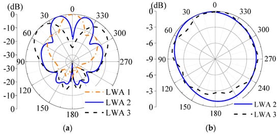
Figure 5.
Normalized radiation patterns of the proposed antenna: (a) xoz-plane, (b) azimuth plane in the main beam directions (θ = 18° for LWA 2 and θ = 44° for LWA 3); w = 27 mm, C = 43.5 mm, and l0 = 17.5 mm.

Table 1.
Slot intervals of the LWAs.
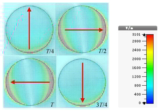
Figure 6.
Electric field distributions of one single circular slot during a period T; w = 27 mm, C = 43.5 mm, l0 = 17.5 mm, and θs = 36°.
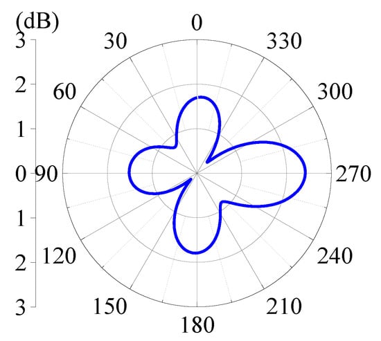
Figure 7.
Axial ratio of LWA 2 in azimuth plane of θ = 18°.
4. Experimental Validation
In order to validate the proposed LWA, two LWAs capable of generating different beam patterns, i.e., LWA 1 for broadside beam and LWA 2 for conical beam, are fabricated, as shown in Figure 8. Two coaxial probes are welded at the rear of the feeding structure. The depth of the probes inside the SIW is set to 3.5 mm. Structural parameters of the two LWAs are listed in Table 2. To conduct the experiments, Port 1s of the LWAs are the input ports that are excited and Port 2s are the output ports that are cascaded to 50 Ohm matched loads. The measurements are carried out in a far-field anechoic chamber. As can be seen in Figure 9, LWA 1 is fixed on the antenna holder. For simplicity, the familiar picture of the measurement setup of LWA 2 is omitted here.
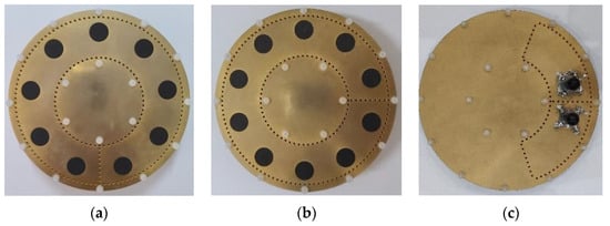
Figure 8.
Prototypes of the proposed LWAs, (a) top view of LWA 1, (b) top view of LWA 2 and (c) bottom view of LWA 1 and 2.
Table 2.
Structural parameters of the LWAs.
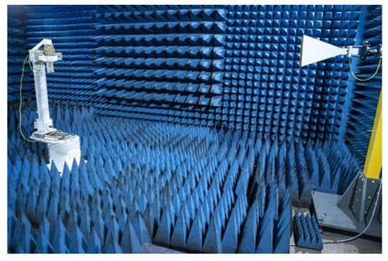
Figure 9.
Illustration of LWA 1 measurement setup.
Figure 10 shows the S-parameters of the two LWAs. It can be observed that the measurement results are basically in good agreement with the simulation results. The difference between them is primarily attributed to the following two aspects: Firstly, it is observed in the two figures that there are transverse deviations against the frequency comparing the simulation and measurement results, which is mainly caused by the permittivity offset of the substrate. Secondly, it is shown that the measured |S21| is lower than the simulated one. On the one hand, the permittivity offset affects the attenuation ratio of the LWAs, i.e., when the permittivity slightly increases, the electric dimensions of the period slots expand, and meanwhile the traveling wave radiates faster along the structure. On the other hand, the assembled coaxial connecters at the two ends of the LWAs have inherent loss, which affects the receiving level at the end of the LWAs. In addition to the above, the secondary cause of the difference is from the fabrication tolerance.
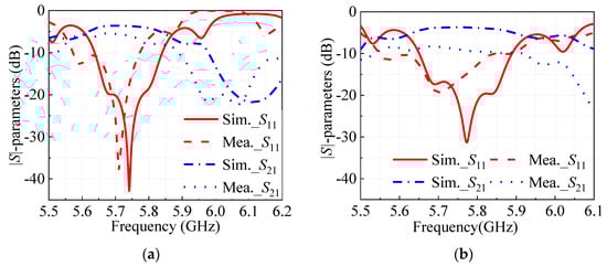
Figure 10.
|S|-parameters of the proposed LWAs: (a) LWA 1 and (b) LWA 2.
Figure 11 depicts the radiation patterns of the two LWAs. The measured results agree well with the counterpart in simulation. It is concluded that the proposed LWA acquires a broadside beam and conical beam through changing the slot interval, which is in accordance with the LWA theory that the beam direction of the spatial harmonic radiation can be rigged via changing the element interval. As the LWA is circularly polarized, we adopt dBic as the unit of the gain of the proposed LWA, which means a ratio of the antenna radiation intensity to the circularly polarized isotropic source. The simulated realized gains of LWA 1 and LWA 2 are 10.5 dBic and 7.16 dBic, while their measured realized gains are 9.75 dBic and 7.93 dBic, respectively. Besides, the simulated efficiencies of LWAs 1 and 2 are 43.27% and 43.14%, respectively. The measured sidelobe levels (SLLs) of LWA 1 in the xoz-plane and yoz-plane are −10.07 dB and −9.24 dB, respectively. Additionally, the measured SLLs of LWA 2 in the xoz-plane and yoz-plane are −8.84 dB and −10.14 dB, respectively. The results show that the SLLs of the two LWAs are similar. Additionally, sidelobes of the LWAs exist due to the relatively large distance (about 2.4 λ0) between radiating slots in any one cut plane of the LWAs. In addition, Figure 12 and Figure 13 show the axial ratio patterns and the axial ratios against frequency, respectively. From the measured and simulated axial ratios shown in the figures, we can see that the two LWAs both present the expected CP property at 5.75 GHz, which verifies the performance of the proposed LWAs. In fact, as depicted in Figure 13, the proposed LWA structure is a narrow-band antenna structure. In order to produce a CP broadside beam or conical beam, the period quantity in the annular structure should be an integer, such as the demonstrated transient electric field distribution in Figure 3.

Figure 11.
Radiation patterns of the proposed LWAs: (a) xoz-plane of LWA 1 at 5.75 GHz, (b) yoz-plane of LWA 1 at 5.75 GHz, (c) xoz-plane of LWA 2 at 5.75 GHz, and (d) yoz-plane of LWA 2 at 5.75 GHz.
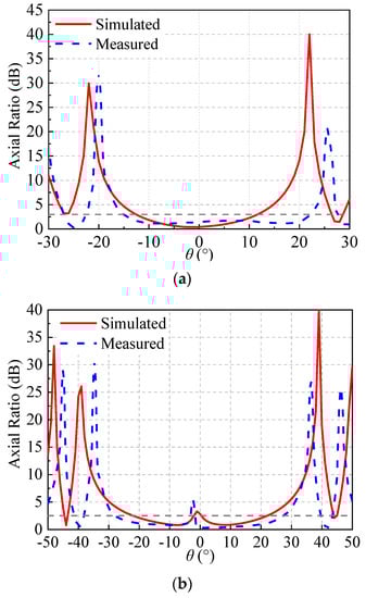
Figure 12.
Axial ratios of the proposed LWAs in xoz-plane: (a) LWA 1 at 5.75 GHz and (b) LWA 2 at 5.75 GHz.
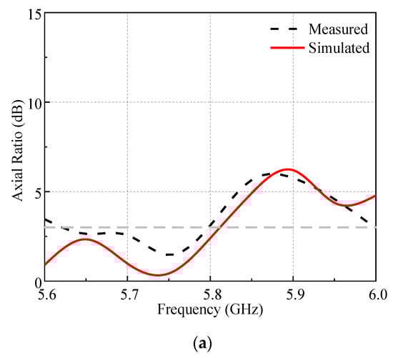
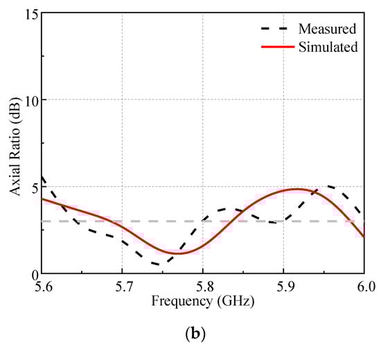
Figure 13.
Axial ratios of the proposed LWAs against frequency: (a) LWA 1 and (b) LWA 2.
Table 3 and Table 4 present the comparison of the proposed LWA and the existing works. Parameters of the broadside beam antennas are listed in Table 3, while parameters of the conical beam antennas are listed in Table 4. It can be concluded that the proposed antennas in this paper have relatively higher realized gains. The thickness of the proposed LWAs is medium, i.e., 0.15 λ0 compared with that of other antennas with similar bandwidth, gain, i.e., 1.53 λ0 in [1], 0.12 λ0 in [6], 0.24 λ0 in [7] and 0.024 λ0 in [9]. It will be further improved in the future work. Thus, the proposed LWA shows good performance and can be a promising candidate for wireless communication applications.
Table 3.
Performance comparison of broadside beam pattern.
Table 4.
Performance comparison of conical beam pattern.
5. Conclusions
In this paper, a kind of CP annular LWA at 5.75 GHz supporting the generation of either designable conical beams or broadside beams via adjusting the structural parameters during the design procedure based on an annular SIW with one single structure format is proposed, which is composed of a radiating layer and a feeding layer. More flexible than the previous work, the proposed antenna works in −1st harmonic mode, which is achieved through adjusting the slot interval so that either a broadside beam or conical beam with different conical angles can be obtained, not merely via adjusting the width of the SIW. Furthermore, deviated circular slots are arranged close to the outer edge of the annular SIW. CP radiation can be achieved when the polarizations of the spatial wave radiated from each circular slots and the −1st spatial harmonic from the leaky travelling wave structure are consistent. It is concluded from the measurement results that the proposed LWA shows good performance in higher gain (9.75 dBic for the broadside LWA and 7.93 dBic for the 13° conical LWA), flexible beam-angle changing, and good CP properties. Additionally, the LWA is easy to fabricate, which is suitable for indoor or outdoor wireless communication applications.
Author Contributions
Methodology, Y.M. and J.W.; Validation, Y.M. and H.Y.; Formal analysis, Y.M. and Y.Z.; Investigation, Y.M., C.P. and X.W. All authors have read and agreed to the published version of the manuscript.
Funding
This work was supported by the National Nature Science Foundation of China (NSFC) Project under grant no. 62031004.
Data Availability Statement
Not applicable.
Conflicts of Interest
The authors declare that there is no conflict of interests regarding the publication of this paper.
References
- He, W.; He, Y.; Zhang, L.; Wong, S.; Li, W.; Boag, A. A Low-Profile Circularly Polarized Conical-Beam Antenna with Wide Overlap Bandwidth. Wirel. Commun. Mob. Comput. 2021, 2021, 6648887. [Google Scholar] [CrossRef]
- Sun, J.; Chen, K.; Qu, K.; Zhao, J.; Jiang, T.; Feng, Y. Controlling Conical Beam Carrying Orbital Angular Momentum with Transmissive Metasurface. Int. J. Antennas Propag. 2021, 2021, 9951644. [Google Scholar] [CrossRef]
- Shen, Z.; Wang, J.; Lee, K.S. Open-Ended Coaxial Waveguide for Conical-Beam Radiation. IEEE Trans. Antennas Propag. 2012, 60, 2518–2521. [Google Scholar] [CrossRef]
- Chenhu, G.; Geng, J.; Zhou, H.; Li, J.; Liang, X.; Zhu, W.; Jin, R.; Ziolkowski, R.W. Truncated Circular Cone Slot Antenna Array That Radiates a Circularly Polarized Conical Beam. IEEE Antennas Wirel. Propag. Lett. 2017, 16, 2574–2577. [Google Scholar] [CrossRef]
- Hirose, K.; Hata, K.; Nakano, H. Modified Crossed-Wire Antennas Radiating a Circularly Polarized Conical Beam. Int. J. Antennas Propag. 2020, 2020, 2759312. [Google Scholar] [CrossRef]
- Lin, W.; Wong, H.; Ziolkowski, R.W. Circularly Polarized Antenna with Reconfigurable Broadside and Conical Beams Facilitated by a Mode Switchable Feed Network. IEEE Trans. Antennas Propag. 2018, 66, 996–1001. [Google Scholar] [CrossRef]
- Nguyen, T.K.; Tran, H.H.; Nguyen-Trong, N. A Wideband Dual-Cavity-Backed Circularly Polarized Crossed Dipole Antenna. IEEE Antennas Wirel. Propag. Lett. 2017, 16, 3135–3138. [Google Scholar] [CrossRef]
- Le, T.T.; Tran, H.H.; Park, H.C. Simple-Structured Dual-Slot Broadband Circularly Polarized Antenna. IEEE Antennas Wirel. Propag. Lett. 2018, 17, 476–479. [Google Scholar] [CrossRef]
- Yang, H.; Fan, Y.; Liu, X. A Compact Dual-Band Stacked Patch Antenna with Dual Circular Polarizations for BeiDou Navigation Satellite Systems. IEEE Antennas Wirel. Propag. Lett. 2019, 18, 1472–1476. [Google Scholar] [CrossRef]
- Cui, L.; Wu, W.; Fang, D. Wideband Circular Patch Antenna for Pattern Diversity Application. IEEE Antennas Wirel. Propag. Lett. 2015, 14, 1298–1301. [Google Scholar] [CrossRef]
- Sutinjo, A.; Okoniewski, M. A Surface Wave Holographic Antenna for Broadside Radiation Excited by a Traveling Wave Patch Array. IEEE Trans. Antennas Propag. 2011, 59, 297–300. [Google Scholar] [CrossRef]
- Monticone, F.; Alù, A. Leaky-Wave Theory, Techniques, and Applications: From Microwaves to Visible Frequencies. Proc. IEEE 2015, 103, 793–821. [Google Scholar] [CrossRef]
- Rudramuni, K.; Majumder, B.; Rajanna, P.K.T.; Kandasamy, K.; Zhang, Q. Dual-Band Asymmetric Leaky-Wave Antennas for Circular Polarization and Simultaneous Dual Beam Scanning. IEEE Trans. Antennas Propag. 2021, 69, 1843–1852. [Google Scholar] [CrossRef]
- Masoumi, M.; Oskouei, H.; Shirkolaei, M.; Mirtaheri, A. Substrate integrated waveguide leaky wave antenna with circular polarization and improvement of the scan angle. Microw. Opt. Technol. Lett. 2021, 64, 137–141. [Google Scholar] [CrossRef]
- Huo, X.; Li, Z. Circularly Polarized Leaky-Wave Antenna Based on Low-Loss Transmission Line. Int. J. Antennas Propag. 2022, 2022, 7224725. [Google Scholar] [CrossRef]
- Ye, Q.C.; Zhang, Y.M.; Li, J.L.; Pedersen, G.F.; Zhang, S. High-Isolation Dual-Polarized Leaky Wave Antenna with Fixed Beam for Full-Duplex Millimeter-Wave Applications. IEEE Trans. Antennas Propag. 2021, 69, 7202–7212. [Google Scholar] [CrossRef]
- Ma, Y.; Wang, J. Theoretical Modeling and Analysis of Circularly Polarized Annular Leaky-Wave Antenna Based on Travelling-Wave Structure. IEEE Access 2021, 9, 29392–29400. [Google Scholar] [CrossRef]
- Ma, Y.; Wang, J.; Li, Z.; Li, Y.; Chen, M.; Zhang, Z. Planar Annular Leaky-Wave Antenna Array with Conical Beam. IEEE Trans. Antennas Propag. 2020, 68, 5405–5414. [Google Scholar] [CrossRef]
- Ip, A.; Jackson, D.R. Radiation from cylindrical leaky waves. IEEE Trans. Antennas Propag. 1990, 38, 482–488. [Google Scholar] [CrossRef]
Disclaimer/Publisher’s Note: The statements, opinions and data contained in all publications are solely those of the individual author(s) and contributor(s) and not of MDPI and/or the editor(s). MDPI and/or the editor(s) disclaim responsibility for any injury to people or property resulting from any ideas, methods, instructions or products referred to in the content. |
© 2023 by the authors. Licensee MDPI, Basel, Switzerland. This article is an open access article distributed under the terms and conditions of the Creative Commons Attribution (CC BY) license (https://creativecommons.org/licenses/by/4.0/).