Article

Research on Intelligent Verification System of High Voltage Electric Energy Metering Device Based on Power Cloud

1
Intelligent Power Equipment Technology Research Center, Wuhan University, Wuhan 430072, China
2
School of Power and Mechanical Engineering, Wuhan University, Wuhan 430072, China
3
Maintenance & Test Center of EHV Power Transmission Company, China Southern Power Grid, Guangzhou 510700, China
*
Author to whom correspondence should be addressed.
Electronics 2023, 12(11), 2493; https://doi.org/10.3390/electronics12112493
Submission received: 10 May 2023 / Revised: 27 May 2023 / Accepted: 30 May 2023 / Published: 1 June 2023

Abstract

:
To address the issues of low efficiency, poor security, insufficient compatibility, and difficulties in traceability associated with high-voltage electric energy metering (HVEEM) device verification methods, this paper proposes a design scheme for a remote verification system (RVS) of such devices based on a power cloud platform (PCP). The system adopts the concept of “high-precision local sampling + remote cloud verification” and develops a local acquisition device with compatibility and high precision to achieve fast acquisition of local electrical parameters. The IEC 61850 communication modeling is utilized to establish unified communication standards between the local device and the PCP. The PCP provides two verification methods: physical error verification based on a multi-channel standard and digital verification based on an improved Backpropagation (BP) neural network simulation model. Leveraging the advantages of power cloud technology, the system enables functions such as electrical energy calculation, remote intelligent error verification, cloud storage, condition monitoring, and early warning. Through testing and application, it has been demonstrated that the system achieves an integration accuracy level better than 0.02. It also exhibits good security, compatibility, and traceability of measurement values while attaining a high level of informatization and intelligence. Particularly, the system shows promising prospects for the remote and efficient verification of large-scale and multi-type high-voltage metering devices.

1. Introduction

High-voltage electric energy metering (HVEEM) plays a crucial role in the development of new power systems, supporting the advancement and application of smart grids, distributed energy resources, and energy conservation and management, as well as intelligent metering. The HVEEM device used in this study mainly consists of a high-voltage energy meter, voltage transformers (PT) and their secondary circuits, current transformers (CT) and their secondary circuits, and related auxiliary circuits. The accuracy of HVEEM directly affects the economic benefits of power enterprises, and the periodic verification of power metering systems, especially HVEEM devices, is of significant importance in ensuring fair transactions among various power generation, distribution, and sales entities. Against the backdrop of global energy transformation towards green and low-carbon sources and China’s dual carbon strategy, there is a pressing need to accelerate the construction of a new power system with renewable energy as its core. As the scale and complexity of the grid continue to expand, the HVEEM system exhibits characteristics such as increased metering hierarchy, a higher number of nodes, and a greater variety of equipment types [1,2,3,4,5]. This places higher demands on the regular and high-precision verification of large-scale HVEEM devices. There is an urgent need for more secure, efficient, cost-effective, reliable, and stable metering device verification methods and technologies. Currently, on-site verification remains the primary method for high-voltage metering device verification. Traditional, manual, on-site verification techniques are mature but suffer from issues such as high workload, low efficiency, high costs, and potential metering security concerns [6,7,8]. In recent years, some domestic power enterprises have developed a distributed functional structure for remote online monitoring systems for energy meters [9,10,11]. However, these systems primarily focus on monitoring the status of energy metering and lack adequate remote verification functionality. Some research institutions have proposed remote verification solutions for gateway energy meters based on high-precision, pre-metering parameter acquisition devices or multi-analog channel switching devices [12,13,14,15,16,17]. These solutions optimize the design of the sampling circuit to improve the sampling accuracy, but they only achieve simple comparisons between the sampled energy measurement from the control terminal and the measured value of the energy meter. As a result, the issue of inadequate traceability of the measurement values still persists. In response, some scholars have developed remote verification systems (RVS) for energy metering based on analog signal online acquisition [18,19,20,21,22,23] and RVS for energy metering devices based on IEC 61850 [24,25,26]. These systems have improved the traceability framework to some extent, but they only support specific types of devices in fixed scenarios, they lack overall compatibility, and their verification methods rely on dedicated hardware resources, thus failing to meet the requirements for large-scale remote and efficient verification.
In response to the various above-mentioned issues associated with traditional, manual, and on-site verification and general remote verification methods for HVEEM devices, this paper proposes an intelligent remote verification solution for HVEEM devices based on power cloud technology. Building upon conventional remote verification methods, the proposed solution adopts an architectural design of “local high-precision multi-channel acquisition + remote controlled power cloud (simulation) standard meter verification.” Specifically, the high-precision local acquisition device incorporates high-precision, split-core current transformer (CT) components and precision resistors. In addition to analog measurement point connections, it features intelligent sensor signal interfaces, effectively enhancing measurement accuracy and equipment compatibility. On the remote-controlled power cloud platform (PCP) side, a simulated standard meter model based on an improved Backpropagation (BP) neural network algorithm is deployed as a cloud service to enable remote digital simulation verification. This approach effectively addresses the challenges associated with large-scale remote and efficient verification while ensuring high traceability. Furthermore, a multi-channel standard meter verification box is available to meet the demand for high-reliability, remote, and real-time physical verification. The testing and application demonstrate that both integrated remote verification methods of the system achieve an accuracy level of 0.02, thereby satisfying the requirements for the remote and efficient verification of large-scale and multi-type high-voltage metering devices.
In the following sections, this paper is organized as follows: Section 2 presents the overall design of the RVS for HVEEM devices based on PCP. Section 3 describes the design of the main modules in the system, including the high-precision, multi-channel local acquisition device (HPMCLAD) and PCP. In Section 4, we elaborate on the key technologies implemented in the system, which primarily include on-site, high-precision simultaneous sampling, IEC 61850-compliant communication modeling, and remote verification based on PCP. In Section 5, we discuss the testing and application of the system. Finally, Section 6 concludes the paper and provides directions for future research.

2. Overall Design of RVS for HVEEM Devices Based on PCP

The RVS for HVEEM devices based on power cloud technology consists of a HPMCLAD, a remote-controlled PCP, intelligent mobile terminals, and a communication network. The HPMCLAD is installed on-site and serves as an Intelligent Electronic Device (IED) connected to the IEC 61850 communication network. It supports the integration of both traditional, analog electrical parameter signals and digital electrical parameter signals, enabling real-time synchronized sampling of the three-phase voltage, current, and electrical parameters of the HVEEM device, and the parameters of the high-voltage electric energy meter. The remote-controlled PCP, based on power cloud technology, comprises a central workstation, client terminals in various substations, and a multi-channel standard meter verification station. The multi-channel standard meter verification station is installed at the central workstation and facilitates high-traceability, remote photoelectric verification. Additionally, a simulated standard meter model based on the BP neural network is established in the cloud to meet the demands of the large-scale remote verification of electric energy meters. The HPMCLAD processes the collected data according to the IEC 61850 protocol and transmits it to the cloud through the communication network, and various terminals utilize cloud services for functions such as electrical energy calculation, error verification, cloud storage, and state monitoring analysis and early warning. Moreover, an intelligent mobile terminal has been developed, allowing personnel to interact with the system throughout the entire process via dedicated electric power Wi-Fi or the internet. For more details, refer to Figure 1.

3. Design of Major Modules for RVS

3.1. Design of HPMCLAD

The local acquisition device is installed on-site and is primarily used for the high-precision data acquisition of electrical parameters such as three-phase voltage, three-phase current, voltage drop across voltage transformers’ secondary circuits, and current transformers’ secondary load, as well as active and reactive energy pulses from high-voltage energy meters. It also performs the conversion of acquired data into the IEC 61850 communication protocol and transmits it in real-time to the PCP through the integrated communication network. Unlike the conventional practice of centrally uploading locally acquired verification data to the remote end for data management, this paper proposes deploying the error verification function in the cloud, which eliminates the high investment in the local standard meter verification module and associated channel switching module. Instead, it emphasizes the high-precision acquisition and measurement of signals. The basic principle is shown in Figure 2.
As shown in Figure 2, the HPMCLAD mainly consists of a main control unit, a high-precision, multi-channel analog acquisition unit, a pulse acquisition unit, and a communication unit. The main control unit adopts a DSP + FPGA architecture, using a 32-bit, high-performance, floating-point digital signal processor, DSP28335, which mainly implements clock synchronization control, bidirectional remote data instruction interaction, local communication management, unit module logic control, and on-site human–machine interaction. The FPGA, in conjunction with the DSP, achieves multi-channel high-speed AD acquisition, interface expansion, and high-speed signal transmission, resulting in performance coupling and greatly improving the real-time reliability of large-capacity data acquisition and processing. The high-precision, multi-channel analog acquisition unit uses a 24-bit, high-precision, wide-temperature-pressure anti-aliasing synchronous sampling chip, AD4134, which can achieve multi-channel synchronous high-precision sampling with a sampling rate of up to 1.5 Msps. Each CT secondary circuit is equipped with a high-precision (0.001 level) split-core CT, further improving the accuracy of three-phase current analog acquisition. By increasing the number of AD sampling chips, the analog synchronous sampling channels are expanded to meet the sampling requirements of multiple busbar high-voltage metering devices for three-phase voltages, currents, and other analog quantities at multiple measurement points. The pulse acquisition unit filters and shapes the active and reactive power pulses of the energy meter, and the main control unit performs pulse synchronous measurement. The communication unit mainly realizes communication management between various functional units locally, and data interaction with the remote PCP. The local acquisition device reads active energy, reactive energy, fundamental energy, harmonic energy, power factor, three-phase voltages, currents, and other measured or internal parameters of the energy meter through the RS485 interface. For PT and CT signals that support the IEC 61850 protocol, they are connected to the communication unit through signal interface circuits. The communication unit uniformly converts various collected data into the IEC 61850 communication protocol and achieves bidirectional interaction with the remote PCP through the comprehensive communication network. The communication method between the on-site and remote PCP is standardized. Compared with conventional RVS that target specific scenarios and signal types, the system described in this paper exhibits better compatibility with devices and signal types from different manufacturers.

3.2. Remote-Controlled PCP

The power cloud is an electric power information cloud platform based on advanced cloud platform technology, integrating multi-source heterogeneous data storage management, data processing services, online information cloud services, etc. It provides strong support for large-scale data computation and persistent storage in RVS for HVEEM [27,28,29,30]. The existing literature focuses on the application of cloud platforms and big data analysis technology in the field of high-voltage metering device measurement, as well as comprising research on intelligent information management of remote online monitoring, fault diagnosis, and the verification achievements of electric energy metering devices. However, there is limited research on the application of cloud-based remote verification for large-scale measurement points. In this paper, based on the principles of error verification of electric energy metering devices and PCP technology, a remote cloud master station system supported by the PCP is designed and developed. It not only achieves functions such as general electric energy metering device status monitoring, fault warning, and data storage, but also realizes two remote verification methods: analog input standard meter verification and cloud-based simulation standard meter digital verification based on a BP neural network. In addition, a mobile intelligent terminal based on the Android platform is developed to meet the user’s convenience needs and need for remote for querying, monitoring, control, and inspection. The composition and implementation principles are shown in Figure 3.
As shown in Figure 3, the remote cloud platform adopts a hierarchical architecture consisting of the edge layer (acquisition layer), infrastructure layer, back-end service layer, and front-end application layer. The edge layer relies on various forms of internet and industrial Ethernet to facilitate data interaction between the local data acquisition devices and the cloud platform. The infrastructure layer includes cloud computing infrastructure, the virtualization of software and hardware resources, distributed cloud storage, and resource management services. It establishes pools of computing resources, storage resources, and network resources, providing infrastructure as a service (IaaS) to support various application services in the cloud platform layer. The platform layer consists of the back-end service layer and front-end application layer. The back-end service layer, based on platform as a service (PaaS) and software as a service (SaaS), realizes functions such as cloud computing for various power measurement data, simulation standard meter model training, shared cloud storage, large-scale error verification, HVEEM device status monitoring, and fault prediction. The front-end layer can directly access the relevant services as needed. The front-end layer adopts the B/S service mode, providing various functions such as verification plan management, measurement node management, statistical report query, event management, and intelligent mobile terminal management. It can meet the diverse application needs of on-site technical personnel. The intelligent mobile terminal, based on the Android platform, mainly realizes on-site verification, verification plan management, statistical queries, on-site monitoring, and other functions, enabling technical personnel to grasp the on-site situation at any time and respond promptly to emergencies. The statistical query functionality is based on historical verification data and involves horizontal and vertical comparison, error trend analysis, and data report visualization. The specific implementation steps include database connection, data preprocessing, statistical calculations, and the presentation of query results. The remote cloud master station uses a quasi-synchronous algorithm to calculate the electrical energy based on the three-phase voltage and current data uploaded by the edge devices such as the local high-precision acquisition unit. It performs error verification according to the specified verification method. At the same time, the results of the electrical energy measurement, verification results, and the electrical energy meter measurement results and parameters are stored in real-time on the cloud for access and query by the front-end application layer.

4. Key Technologies

4.1. On-Site High-Precision Simultaneous Sampling

Precise, synchronized sampling is a key factor in ensuring the reliability of remote verification results. The RVS for HVEEM devices not only needs to achieve high-precision sampling of the analog signals, including three-phase currents, voltages, PT secondary-side voltage drops, and CT secondary-side loads at multiple points in the local substations, as well as digital signals such as active and reactive power pulses from energy meters, but also needs to ensure the synchronization requirements of the sampling process in order to enhance the accuracy of remote verification. For pulse signals and intelligent sensor signals based on the SV/GOOSE protocol, the sampling technology has achieved a high level of accuracy. This paper focuses on the introduction of multi-channel, analog, high-precision sampling and high-synchronization accuracy sampling methods. The principle of the HPMCLAD is shown in Figure 4.
The voltage analog signals are collected using a high-precision voltage divider circuit built with precision resistors to scale down the voltage. The current analog signals are collected using 0.01-level, high-flux, high-stability, wide-temperature type split-core current transformers (CTs). The I/V conversion circuit is designed in a zero-load manner, and the signal is buffered and amplified by a high-precision, low-noise operational amplifier to improve the accuracy of the analog-to-digital conversion. The analog-to-digital conversion is performed by a 24-bit, four-channel, synchronous sampling, 1.5 MSPS high-precision, aliasing-free analog-to-digital converter, AD4134, to reduce the conversion error. By cascading multiple AD converters, up to 32 channels of synchronized analog signal acquisition can be achieved with a single acquisition module. The AD4134 chip incorporates an anti-aliasing analog filter and oversampling digital filter, and it also includes a high-precision voltage reference source, which greatly simplifies the design of the input drive and reference power supply circuits. The serial data output pins and associated control pins of the AD4134 chip are connected to the FPGA through a minimal interface mode. The sampling data are transmitted at high speed and high throughput using the SPI interface, which reduces the number of I/O interfaces, simplifies the peripheral circuit design, and minimizes the impact of traditional multi-channel routing on the PCB layout.
In addition, synchronous pulse input IO + Timer is employed for time synchronization, with a timing accuracy better than 1 μs. Under typical clock frequencies, the synchronization clock accuracy can reach 7 ns. Furthermore, reserved interfaces for GPS and BeiDou timing are utilized to ensure the reliability of the clock synchronization. Building upon the foundation of high-precision clock synchronization design, synchronous sampling is implemented by capturing the rising edge of the next system clock after receiving the synchronous acquisition command as the reference timestamp for data acquisition. This approach further reduces synchronization sampling errors and enhances the synchronization accuracy of multi-channel sampling.

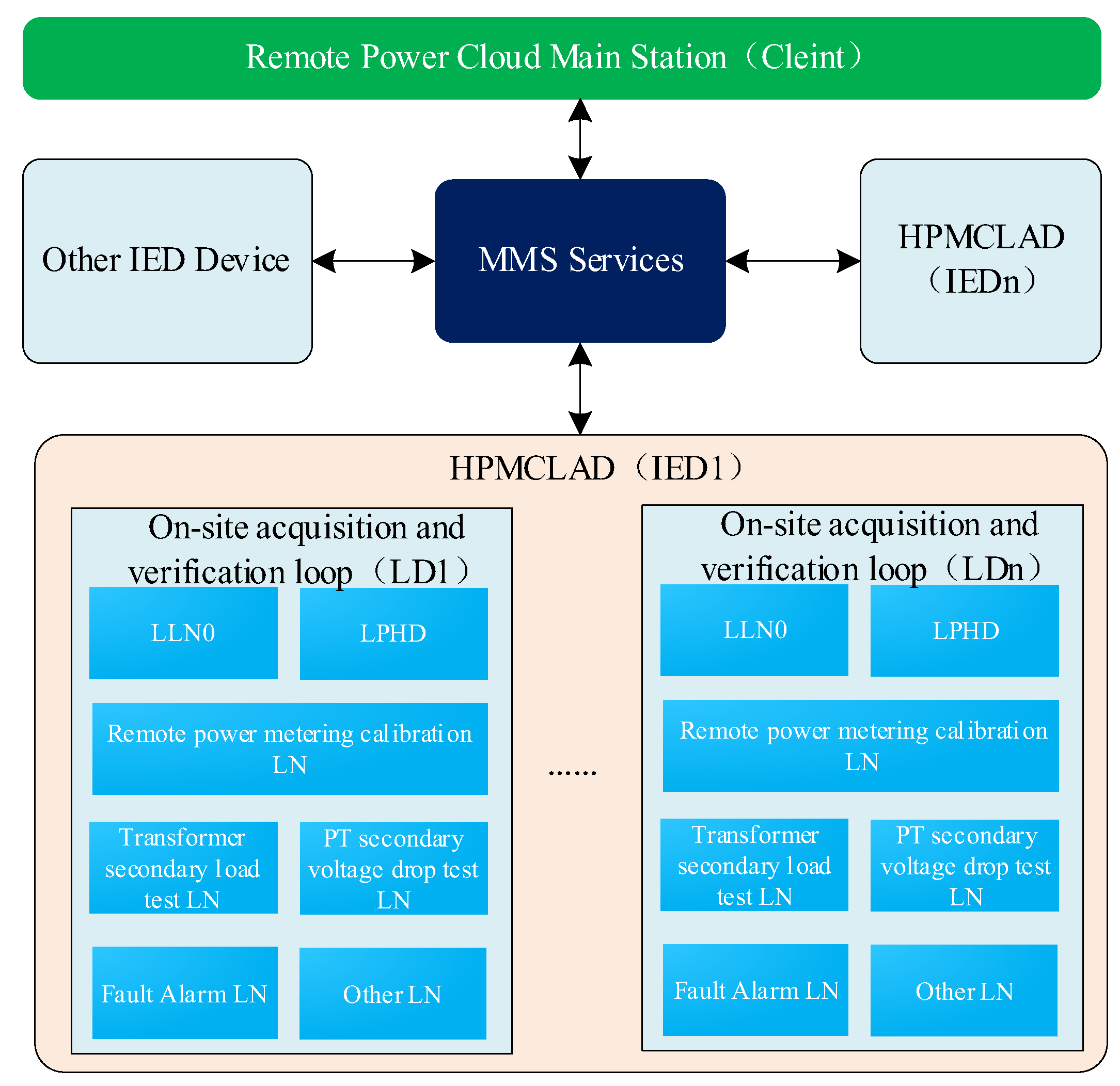
4.2. IEC 61850 Compliant Communication Modeling

Currently, there are various manufacturers of high-voltage metering devices in the market, with different communication formats and signal types. In the same substation, there may be situations where multiple manufacturers, models, and communication formats of high-voltage energy metering devices are installed simultaneously due to maintenance and technical upgrade cycles. The existing remote energy metering verification systems were often developed based on specific device models and communication formats, resulting in poor dynamic scalability and communication compatibility, making them unable to meet the remote verification requirements of large-scale gateway points in regional substations. In this paper, based on the compatibility access of the front-end, high-precision local acquisition device with electronic, digital sensors, or energy meters, a communication solution for the RVS based on the IEC 61850 communication standard is proposed. The aim of this solution is to address the diverse types and signal formats of energy meters and their associated sensors which are distributed at gateway metering points. By achieving compatibility access through the front-end local acquisition device, the communication management unit of the local acquisition device completes the IEC 61850 protocol conversion, message parsing, and synthesis of the collected data from gateway points. This abstracts the local acquisition device as an intelligent device that uniformly accesses the IEC 61850 communication network, greatly improving the system’s compatibility and scalability. The IEC 61850 communication standard adopts object-oriented data modeling techniques, which provide good data self-description and network independence [31,32]. Drawing on the communication modeling methods used in substations, the communication modeling of the RVS is performed, as illustrated in Figure 5.
As shown in Figure 5, referring to the IEC 61850 communication modeling approach for intelligent substations, the HPMCLAD is defined as an Intelligent Electronic Device (IED), with the Remote Power Cloud Main Station serving as the Client and the field acquisition device and other edge devices serving as the Server. The bidirectional interaction between the two is achieved through the MMS service mechanism. The LN classes required for the verification process, as determined by the IEC 61850-7-4 standard, are selected and appropriately extended. Each measurement loop of the field acquisition device is defined as a Logical Device (LD), and under each LD, multiple logical nodes (LN) are defined according to the remote verification process, including verification circuit management, metering error verification, PT secondary voltage drop testing, current transformer secondary load testing, fault alarms, and other nodes. The Verification Circuit Management LN primarily includes common information such as measurement lines, devices, self-description of the field acquisition device, and verification plans. The Metering Error Verification LN is based on the standard-defined Measurement LN (MMTR) logical node class and is appropriately extended to include parameters for remote verification settings, error verification results, and associated device sample values. The PT Secondary Voltage Drop Testing and Current Transformer Secondary Load Testing LNs are based on the standard-defined Extended Measurement LN (MMXU) and are appropriately extended to include specific data object (DO) descriptions of the test results. The Fault Alarm LN defines common faults during the remote verification process to ensure timely reporting of various verification data which are exceeding limits. Some of the extended DO parameters are shown in Table 1.

4.3. Remote Verification Based on PCP

Traditional RVS often adopt the approach of locally performing high-precision data acquisition for verification and uploading the results to a remote back end. The remote verification functionality mainly involves remote control of the verification commands and information management of the sampled verification data. In this approach, the devices to be verified and the verification equipment (such as standard verification modules) still operate in the same environment. However, for a large number of access points requiring verification, this method is inefficient and incurs high equipment investment and maintenance costs. Some RVS [18,19,20,21] have employed a design approach of “local high-precision acquisition + remote verification.” However, in these systems, after the energy measurement is completed by the local acquisition device, only a simple comparison is made between the measured energy and the value of the meter under test. An uninterrupted comparison chain has not been effectively established. In terms of functionality, these systems focus more on intelligent, information-based status monitoring and data management. The verification results of the measurement errors can only serve as general references and cannot guarantee the traceability of the measurement values.
To address the aforementioned issues and deficiencies, based on the principle of verification using high-voltage energy meters and leveraging the advantages of the PCP, this paper proposes a deployment of the energy meter error verification functionality on the remote-controlled PCP. Two remote verification methods are provided: one based on a multi-channel pulse standard verification device and the other based on a BP neural network simulation standard meter.

4.3.1. Remote Verification of Multi-Channel Pulse Standard Verification Device

Taking full advantage of the powerful computing capabilities, fast response, abundant resources, and high reliability of the PCP, a significant amount of computational work is allocated to the PCP. The front-end local acquisition device focuses on local high-precision data acquisition and uploading. After aggregating and organizing the massive amount of collected data in the cloud, advanced metering algorithms are employed for energy calculation. Simultaneously, the front-end, high-precision local acquisition device, intermediate communication logic links, and remote energy calculation method are integrated and abstracted into a single energy meter. This energy meter is then used as a reference standard after undergoing accuracy calibration with a higher-grade standard meter. The verification of the meter under test is conducted using a multi-channel pulse standard calibration device. This verification approach not only significantly reduces the hardware performance requirements of the local acquisition device but also reduces the investment cost in basic hardware infrastructure. Moreover, it ensures the continuity of the measurement value transmission chain and greatly improves the efficiency of remote verification work. The basic schematic diagram can be seen in Figure 6.
As shown in Figure 6, the HPMCLAD acquires the active and reactive power pulses of the meter under test, as well as the line electrical parameters, with high precision. These measurements are then transmitted through the comprehensive communication network to the power cloud. In the power cloud, cloud services are invoked, and advanced algorithms are employed to perform energy calculation. During the energy calculation process, the program utilizes the four most recently sampled values in chronological order. It applies a third-order Lagrange interpolation algorithm with Ts/4 as the reference to refine the interpolation and perform resampling. The accumulated energy is computed using dot product and metering algorithms, while the frequency is calculated using a quasi-synchronous algorithm. The front-end, high-precision acquisition device and the cloud-based energy metering system are integrated and verified through the use of a three-phase standard source and a 0.01-level standard meter. The accuracy of the energy measurement system exceeds the 0.02 level, making it suitable for verifying the accuracy of downstream energy meters as a standard reference source.
The multi-channel standard verification device supports up to 16 pulse inputs, enabling the simultaneous remote verification of eight metering devices at different points. The massive amount of collected data stored in the cloud is synchronized and organized. The pulse conversion circuit generates a multi-channel standard verification device by setting the energy threshold and converting the collected data into metering pulses. The multi-channel standard verification device utilizes a high-precision and high-stability 50 MHz clock as the high-frequency reference clock for counting the input pulses (low-frequency pulses). Depending on the grade of the meter being verified, the number of pulses to be collected during the verification sequence, denoted as N, is determined. The verification sequence starts from the rising edge of the first low-frequency pulse and ends at the rising edge of the Nth low-frequency pulse. Simultaneously, the number of high-frequency standard pulses is recorded. The energy measurement value for the corresponding period is obtained by multiplying the number of pulse collections by the pulse constant. Furthermore, the cloud-based verification program formulates the verification plan, and the program automatically “soft switches” the verification channels in a First-In-First-Out (FIFO) manner according to the set parameters. This enables efficient utilization of the verification channels, avoiding the inefficiency and high cost associated with traditional hardware switching methods. As well, it enhances the support capability for large-scale remote verification.

4.3.2. Construction of Simulation Standard Meter Based on Improved BP Neural Network

The verification method based on the multi-channel standard verification device has good traceability of measurement values. However, it is still limited by the number of channels and requires long-term, high-load operation, which increases maintenance costs. It cannot fully meet the increasingly growing demand for the high-speed parallel verification of large-scale access to metering devices at different points. To address this limitation, considering the complexity of the electric energy metering system and the various nonlinear parameters that are influenced by electromagnetic factors, a simulation standard meter model based on an improved Backpropagation (BP) neural network is constructed in the cloud. This leverages the strong nonlinear mapping capability of artificial neural networks to achieve low-cost and efficient remote verification relying on the advantages of cloud computing power.
The Backpropagation (BP) neural network is a learning algorithm for neural networks, consisting of an input layer, hidden layers, and an output layer. Each neuron receives input responses from the network and generates connection weights. By reducing the direction of the expected output and actual output error, the connection weights are iteratively adjusted layer by layer from the output layer, running until the global error reaches a set threshold. This process achieves a nonlinear fitting effect and exhibits good generalization capabilities for different data. Some researchers have proposed a neural network-based calibration method for energy meters [33,34,35,36,37], which partially validates the feasibility of this approach. It provides valuable insights for the large-scale, parallel remote verification of energy metering devices based on the electric PCP. However, the model training samples in this research have low resolution and a small scale. Additionally, only a few specific data points were compared, indicating the need for further optimization in terms of model accuracy and usability. To address this, a simulation standard meter model based on an improved BP neural network is constructed. It involves comparing the measurement values obtained from the input of sampled three-phase electrical parameters to the standard meter model with the measurement values of the energy meter, thus performing error verification.
The simulation standard meter model is developed based on the learning and training of measured sample data from precision standard sources and standard energy meters (with a precision level of 0.01). During the training process, improvements are made to the algorithm using additional momentum methods and dynamic adaptive learning rate methods. As shown in Figure 7, a programmable three-phase standard source is used to simulate the full range of parameters at the highest resolution. It records parameters such as the three-phase voltage, three-phase current, frequency, power factor, and active/reactive power measurement synchronization of the standard meter. This approach maximizes the generation of a large number of training samples with finer granularity and more comprehensive readings. The purpose of this study is to utilize a trained neural network to simulate the behavior of a standard meter. By replacing the conventional standard meter with a mature neural network, we aim to achieve accurate power predictions. The selection of the neural network structure is crucial as it possesses its own distinct characteristics. The input variables in this study are defined as three-phase current, three-phase voltage, frequency, and phase. These variables capture essential electrical parameters in the system. The objective is to predict the corresponding power value (P) using a BP neural network. Based on engineering experience and considerations of the convergence speed and error accuracy, a single hidden layer structure of 4-16-1 is chosen for the BP neural network. This architecture comprises 4 input nodes, 16 neurons in the hidden layer, and 1 output node. The specific configuration of the hidden layer aims to strike a balance between computational efficiency and predictive performance. The basic structure of the BP network [33,36,37] is shown in Figure 8. The learning and training process is performed by minimizing the approximation error between the network output and the standard meter output values, and using them as the convergence criterion.
Although the BP neural network algorithm is widely used, it has several limitations such as slow convergence and the tendency to converge to local optima. To accelerate the training convergence speed, an improvement is made to the traditional BP neural network algorithm by adding a momentum term to the weight update term and employing accelerated gradient descent for convergence optimization [36,37,38,39].
Standard BP neural network weights update term:
Δ ω ( k ) = η g ( k )
In Equation (1), Δω(k) represents the parameter adjustment value at the k-th iteration, η denotes the learning rate, and g(k) signifies the gradient computed at the k-th iteration.
Adding the momentum term parameter, the update term becomes:
Δ ω ( k ) = η [ ( 1 μ ) g ( k ) ] + μ g ( k 1 )
In Equation (2), μ represents the momentum factor, which is typically chosen to be between 0 and 1. Its core idea is to accelerate or decelerate the gradient descent search based on the consistency of the current gradient descent direction with the previous direction.
The value of the learning rate η has a significant impact on the convergence speed and convergence quality. When the value is too large, the convergence process is prone to oscillations. On the other hand, when the value is too small, the convergence speed becomes excessively slow. The selection of an appropriate learning rate is challenging when using a fixed learning rate approach. To address this issue, an adaptive learning rate factor based on the computation of the gradient direction is introduced, enabling the adaptive determination of the learning rate.
η ( k ) = σ ( k ) η ( k 1 )
σ ( k ) = 2 λ
In Equations (3) and (4), η(k) represents the adaptive learning rate factor at the k-th iteration, while λ represents the gradient direction. When the computed gradient g(k) at the k-th iteration is larger than the previous computed gradient, λ is set to 1. This amplifies the learning rate η to accelerate convergence. Conversely, when g(k) is smaller than the previous gradient, λ is set to −1, causing the learning rate η to decrease and ensuring convergence while avoiding oscillations. The simplified algorithm flow is depicted in Figure 9.
The training implementation steps are as follows [37,38,39]:
Step 1: Prepare the training dataset: Select a set of standard source voltage, current, frequency, and phase values ( x = { V o l , C u r , F r e , P h a } ) as inputs. Also, gather the corresponding measurements from the 0.01-level standard meter as the expected output ( y = { P o w e r } ). Collect a sufficient number of historical data samples and organize them as input vectors X = ( x 1 , x 2 , x n , 1 ) , and their corresponding expected output vectors as Y = ( y 1 , y 2 , , y n ) .
Step 2: Normalize the training data: Perform data normalization on the input vectors X and output vectors Y to bring them within a common range or scale. This step ensures that the training data are consistent and avoids issues related to different measurement units or magnitudes.
Step 3: Define the neural network structure: Determine the architecture of the backpropagation (BP) neural network. In this case, choose a single hidden layer with 4 input nodes, 1 output node, and 16 hidden nodes (4-16-1 configuration).
Step 4: Initialize network parameters: Set the initial values for various parameters of the neural network, including the number of input nodes ( n in = 4 ), output nodes ( n out = 1 ), and hidden nodes ( n hid = 16 ). Specify the maximum iteration count ( n max = 1000 ), training error threshold ( ϵ lim = 0.0001 ), initial learning rate ( η ini = 0.5 ), and momentum factor ( μ = 0.8 ).
Step 5: Randomly initialize weights and thresholds: Initialize the connection weights (W) and thresholds (b) of all neurons in the network randomly within the range (0, 1). Also, set the initial values of weight and threshold change rates as Δ W ( 0 ) = Δ b ( 0 ) = 0 .
Step 6: Iterate the training process. Initialize the iteration count: k = 0 . Initialize the training error: E train ( 0 ) = . While k < n max and E train ( k ) > ϵ lim , perform steps 7 to 12. Otherwise, proceed to step 13.
Step 7: Perform forward propagation to compute the output values.
Weighted input from input layer to hidden layer:
z hid ( k ) = W in 2 hid ( k ) x + b hid ( k )
Activation value of the hidden layer:
a hid ( k ) = f ( z hid ( k ) )
Weighted input from hidden layer to output layer:
z out ( k ) = W hid 2 out ( k ) a hid ( k ) + b out ( k )
Activation value of the output layer:
a out ( k ) = f ( z out ( k ) )
Step 8: Calculate the output layer error.
Error of the output layer:
E out ( k ) = y ( k ) a output ( k )
Step 9: Perform backpropagation to update connection weights and thresholds from output layer to hidden layer:
Update weights and thresholds from hidden layer to output layer:
Δ W hid 2 out ( k + 1 ) = E out ( k ) f ( a out ( k ) )
W hid 2 out ( k + 1 ) = W hid 2 out ( k ) + η ( k ) ( 1 μ ) Δ W hid 2 out ( k + 1 ) a hid T ( k ) + μ Δ W hid 2 out ( k ) a hid T ( k )
Δ b out ( k + 1 ) = E out ( k )
b out k + 1 = b out ( k ) + η ( k ) Δ b out ( k + 1 )
Step 10: Calculate the hidden layer error through backpropagation:
Calculate the error of the hidden layer:
E hid ( k ) = W hid 2 out T ( k ) E out ( k ) f ( a hid ( k ) )
Step 11: Update connection weights and thresholds from input layer to hidden layer:
Update weights and thresholds from input layer to hidden layer:
Δ W in 2 hid ( k + 1 ) = E hid ( k ) f ( a hid ( k ) )
W in 2 hid ( k + 1 ) = W in 2 hid ( k ) + η ( k ) ( 1 μ ) Δ W in 2 hid ( k + 1 ) x T + μ Δ W in 2 hid ( k ) x T ( k )
Δ b hid ( k + 1 ) = E hid ( k )
b hid ( k + 1 ) = b hid ( k ) + η ( k ) Δ b hid ( k + 1 )
Step 12: Update iteration count, training error, and adaptive learning rate:
Update iteration count:
k = k + 1
Update training error [34]:
E train ( k ) = 1 2 ( a out y ) 2
Update learning rate according to the following formula based on Equations (3) and (4):
η ( k ) = { 2 η ( k 1 ) , E train ( k ) > E train ( k 1 )   2 1 η ( k 1 ) ,   E train ( k ) E train ( k 1 )
Step 13: Output the network’s predicted output:
y pre = a out
These steps describe the training process of the backpropagation neural network. The activation function used is the Sigmoid function, denoted by f(x), and its derivative is f′(x). The weights and thresholds are updated using the learning rate η and the momentum factor μ.
f ( x ) = sigmoid ( x ) = 1 / ( 1 + e x )
f ( x ) = s i g m o i d ( x )   ×   ( 1 s i g m o i d ( x ) )
The formula for calculating the relative error of the test meter is given as follows [40]:
γ = M M 0 M 0 × 100 %
In Equation (25), M represents the measurement result of the test meter, and M 0 represents the measurement result of the 0.01-grade, high-precision standard meter.
Experimental tests have shown that the measurement accuracy of the simulated standard meter closely approximates the 0.01-level physical standard meter with an overall precision of 10−5. This achievement effectively reduces the hardware investment and fully leverages the computational advantages of the electric PCP. It represents a valuable exploration into achieving efficient remote verification of large-scale sampled data. The proposed model is deployed as a cloud service, enabling the rapid remote verification of massive data from high-voltage electric energy meters.

5. Testing and Application Discussion

Through the local acquisition device, communication network, and remote-controlled cloud platform, two different approaches were tested and validated: the cloud-based, multi-channel pulse standard verification device and the simulated standard meter based on the improved BP neural network. The experiments utilized high-precision, three-phase standard simulated power sources and digital power sources as test inputs. Different loads were simulated using a load box to represent both balanced and unbalanced conditions. The power factors which were tested were 1, 0.5 lagging (L), and 0.8 leading (C). A comparison was made between the output results of the cloud-based multi-channel pulse standard verification device, the simulated standard meter, the 0.02-level standard meter, the 0.05-level standard meter, and the 0.01-level precision standard meter by calculating the differences. The experimental results are presented in Table 2. In this context, γ M represents the multi-channel pulse standard error, γ S represents the simulated standard meter error, γ 0.02 represents the 0.02-level standard meter error, and γ 0.05 represents the 0.05-level standard meter error, which are calculated according to Equation (25). “Ib” represents the reference current, which refers to the stable value of the current at the nominal voltage and frequency. It is typically half of the current meter’s range. On the other hand, “Imax” represents the maximum current, which denotes the highest value of the load current. It is generally the upper limit of the current meter’s range.
As shown in Table 2, the integrated multi-channel standard calibration approach achieves a metering accuracy close to the 0.01 level, significantly surpassing the 0.02 level. The metering accuracy of the simulation standard meter based on the improved BP neural network is slightly lower than the 0.01 level but still better than the 0.02 level and significantly superior to the 0.05 level. Both calibration approaches meet the accuracy requirements for the remote calibration of power metering devices at the 0.2 level and below. The test results also indicate that the metering accuracy of the two calibration approaches is influenced by the load conditions. Under balanced load conditions, the performance is better compared to unbalanced conditions. Additionally, under the same power factor and load balance, there is a tendency for the metering accuracy to degrade when the load is biased. Furthermore, although the simulation standard meter based on the improved BP neural network demonstrates good approximation accuracy (better than 10−5) to the 0.01 level precision standard meter during modeling and training, its actual testing accuracy is slightly lower than the accuracy level achieved during modeling. This can be attributed to factors such as insufficient granularity in the modeling data sampling points and the absence of load conditions in the data samples.
Currently, the designed system described in this paper has been deployed and is undergoing trial operation. Field applications have demonstrated that the system achieves its intended functionalities, enabling the compatibility access and rapid remote intelligent calibration of widely distributed electronic and digital energy meters in various substations. The remote calibration feature realizes standardization, automation, and intelligence. After initial wiring, remote calibration, querying, and monitoring can be performed solely at the remote-controlled center station, client-side, or intelligent mobile terminals. This system proves to be particularly beneficial for scenarios involving large-scale equipment integration, as it significantly reduces equipment investment and improves operational efficiency. In comparison with the traditional meter calibration method, the relevant performance parameters are presented in Table 3.
The proposed improvement approach in this paper overcomes the limitations of the traditional validation methods, such as high workload, low efficiency, high cost, insufficient compatibility, difficult traceability, and lack of support for the parallel calibration of large-scale metering devices. By adopting the “on-site high-precision sampling + remote cloud-based validation” approach, the system introduces a novel solution that fully harnesses the power of cloud platforms. It outperforms traditional methods in terms of efficiency, safety, compatibility, traceability, and reliability. The proposed system significantly enhances the accuracy of high-voltage metering device validation. The remote validation platform offers two validation methods: multi-channel standard physical error validation and validation based on an improved BP neural network simulation table. Leveraging the advantages of power cloud technology, the system realizes various functions, including energy calculation, remote intelligent error validation, cloud storage, and status monitoring and alerts. Particularly, it provides a promising application prospect for large-scale and diverse high-voltage metering devices.

6. Conclusions

This paper proposes an intelligent remote calibration solution for high-voltage power metering devices based on the PCP, which is closely related to the construction of new power systems. This solution can provide remote monitoring, data analysis, energy management, and operation support for various types of sites such as hydroelectric power stations, renewable energy facilities, and converter stations (substations), thereby promoting the sustainable operation and optimized management of new power systems. The solution adopts a pre-processing, high-precision data acquisition approach and remote cloud-based error calibration. The on-site data acquisition devices are designed with high precision and compatibility, using the IEC 61850 unified communication standard. This greatly enhances the security, system compatibility, and scalability of the solution. At the cloud end, two methods are provided for calibration: multi-channel standard physical calibration and digital calibration based on an improved BP neural network simulated standard meter. Leveraging the computational advantages of the power cloud, the solution improves work efficiency and reduces the investment required for traditional channel switching equipment. It provides valuable insights for remote calibration in scenarios involving the large-scale deployment of calibration points. In both methods, the “standard meter” adopts an integrated error concept and is calibrated against a precision standard meter. The structure is simplified, and the traceability of the measurement values is relatively good. However, due to the inherent limitations of BP neural network technology, further research is needed to refine the modeling and theoretical support of the simulated table under different load conditions. Additionally, the high-performance implementation of the system relies on the computational advantages of the cloud platform and the high reliability of high-speed communication networks. Further research is required to ensure the integrity and robustness of the data traceability system throughout the entire process.
The test application demonstrates that the system can achieve its designed functionality with an integrated error accuracy at the 0.02 level, exhibiting high precision. Furthermore, the system shows strong compatibility and scalability, along with a good level of informatization and intelligence. It is capable of meeting the remote calibration requirements for large-scale, high-voltage metering devices, ensuring the safe, efficient, cost-effective, reliable, and stable conduct of meter calibration work.

Author Contributions

F.Z. designed and developed the system and methodology with J.G., F.Y. and Y.S. test the example and write the manuscript. B.T. and D.Y. helped to test and validate the model. All authors have read and agreed to the published version of the manuscript.

Funding

This work was supported in part by the National Key Research and Development Program of China under Grant No. 2020YFB1709700, entitled “Key Technologies Research and Development of Intelligent Operation and Maintenance for High-Security Equipment”, and by the Southern Power Grid Company Technology Program of China under Grant No. CGYKJXM20200236, entitled “Research and Application of Field Inspection Technology for Metering Devices”.

Data Availability Statement

The raw/processed data cannot be shared at this time. Due to the nature of this research, participants of this study did not agree for their data to be shared publicly.

Acknowledgments

The authors gratefully acknowledge the support of the National Key Research and Development Program of China (Grant. 2020YFB1709700), and the Southern Power Grid Company Technology Program of China (Grant. CGYKJXM20200236).

Conflicts of Interest

The authors declare no conflict of interest.

References

  1. Yang, L.; Zhang, D.; Lin, G.; Song, Q.; Meng, Q.; Pan, F.; Liu, C. Research on remote calibration and online monitoring system of electric energy metering device. J. Phys. Conf. Series. 2019, 1303, 12119. [Google Scholar] [CrossRef]
  2. Ding, Q.X. Improvement of Fault Diagnosis Technology for High-Voltage Power Metering Systems. Electr. Power Masses 2022, 8, 58–59. [Google Scholar]
  3. Li, G.; Jiang, X.Y.; He, D.Y.; Wu, Y.L. Research on Calibration Method of Electric Energy Metering System Based on Electronic Current Transformers. Autom. Instrum. 2021, 5, 92–96+101. [Google Scholar] [CrossRef]
  4. Sun, L. Research on Overall Calibration Technology of High Voltage Electric Energy Metering Devices in Distribution Networks. China New Technol. New Prod. 2019, 22, 47–48. [Google Scholar] [CrossRef]
  5. Yu, L.; Jing, J.; Liu, X.; Fan, J. Application of Intelligent Fault Diagnosis Technology for Power Metering Devices in the Context of Big Data. Power Syst. Equip. 2023, 2, 131–133. [Google Scholar]
  6. Wu, Y.X.; Liu, K.P.; Qin, L.; Zheng, X.; Wang, X.H. Research on Measurement Error of High-Voltage Direct Current Energy Metering Systems. Electr. Meas. Instrum. 2022, 9, 146–152. [Google Scholar] [CrossRef]
  7. Meng, Z.; Li, H.; Zhang, C.; Chen, M.; Chen, Q. Research on the reliability of capacitor voltage transformers calibration results. Measurement 2019, 146, 770–779. [Google Scholar] [CrossRef]
  8. Xia, T.; Lei, M.; Zheng, X.; Liu, C.C.; Yan, L.Q. Design of Online Monitoring System for Intelligent Substation Energy Metering Devices. Instrum. Tech. 2018, 5, 18–21. [Google Scholar] [CrossRef]
  9. Guan, S.L.; Zhao, Y.C.; Liu, F.R.; Zhao, Y.F. Operation Status and Improvement Measures of Remote Verification System for Electric Energy Metering Devices. China Metrol. 2018, 2, 105–106. [Google Scholar] [CrossRef]
  10. Lin, W.B.; Chen, L.; Xiao, Y.; Qian, B.; Xiao, Y.; Huang, S.L.; Zhao, W. Current Status and Development Trend of On-site Verification Technology for Electric Energy Meters. Electr. Meas. Instrum. 2016, 12, 1–6+41. [Google Scholar] [CrossRef]
  11. Zhu, K.; Yue, C.; Li, Z.; Yu, J.; Liu, Y. Study on hot-line calibration for 10kV watt-hour metering device. In Proceedings of the 2019 IEEE Sustainable Power and Energy Conference (iSPEC), Beijing, China, 21–23 November 2019; pp. 2675–2679. [Google Scholar] [CrossRef]
  12. Zhang, D.Q.; Yang, L.; Song, Q.; Meng, Q.L.; Pan, F. Development of a Multi-Channel Analog Data Acquisition Device for Remote Verification of Gateway Electric Energy Metering Devices. Electr. Meas. Instrum. 2022, 9, 181–187. [Google Scholar] [CrossRef]
  13. Cheng, F.Y.; Cao, M.; Lin, Z.A.; Wang, H.L.; Chen, Z.; Li, B.; Tang, B. Design of the Integrated Intelligent Detection Platform for Electric Energy Measuring Device. E3S Web Conf. 2020, 194, 3012. [Google Scholar] [CrossRef]
  14. Wang, Z.; Wang, H.Y.; Zeng, W.J.; Su, Y.P.; Duan, Y.J. Signal Reproduction Technology for Energy Meter Calibration Platform Based on Real Power Simulation. J. Northwest Univ. Nat. Sci. Ed. 2022, 52, 69–75. [Google Scholar] [CrossRef]
  15. Djokic, B.; Parks, H. Calibration of Electricity Meters with Digital Input. In Proceedings of the 2018 Conference on Precision Electromagnetic Measurements, Paris, France, 8–13 July 2018; pp. 1–2. [Google Scholar] [CrossRef]
  16. Li, H.; Chen, Q.Z.; Ma, H.B.; Xu, Z.M. Research on Intelligent Diagnosis Method for Electric Energy Metering Devices. Foreign Electron. Meas. Technol. 2019, 8, 52–56. [Google Scholar] [CrossRef]
  17. Du, J.; Fan, L.; Cui, Y.; Liang, H.; Liu, Y. An intelligent measuring device and its function realization method for deepening application in substation. In Proceedings of the 2022 IEEE 6th Advanced Information Technology, Electronic and Automation Control Conference (IAEAC), Beijing, China, 3–5 October 2022; pp. 929–932. [Google Scholar] [CrossRef]
  18. Tan, H.Y.; Yao, H.J.; Huang, Y.; Wang, H.N.; Zhao, Z.H.; Liu, Y. Error Correction Method for Smart Energy Meter Field Calibration System under Non-standard Conditions. In Proceedings of the 2020 4th International Conference on Smart Grid and Smart Cities (ICSGSC), Osaka, Japan, 18–21 August 2020; pp. 149–153. [Google Scholar] [CrossRef]
  19. Wu, Y.; Chen, C.; Yao, D.; Cao, R. Design of online calibration device for electric energy metering based on gps synchronous sampling. IOP Conf. Ser. Mater. Sci. Eng. 2019, 677, 42097. [Google Scholar] [CrossRef]
  20. Dubara, H.V.; Parihar, M.; Ramamritham, K. Smart Energy Meter Calibration: An Edge Computation Method: Poster. In Proceedings of the Twelfth ACM International Conference on Future Energy Systems, Online, 28 June–2 July 2021; pp. 280–281. [Google Scholar] [CrossRef]
  21. Li, Z.; Li, Q.; Wu, Z.; Li, Z. Research into an online calibration system for the errors of voltage transformers based on open–closed capacitor. Energies 2018, 11, 1455. [Google Scholar] [CrossRef]
  22. Li, Y.; Xu, B. Research on online calibration system based on ABB industrial robot. In Proceedings of the 2019 Chinese Automation Congress (CAC), Hangzhou, China, 22–24 November 2019; pp. 1299–1305. [Google Scholar] [CrossRef]
  23. Zhu, Z.; Dai, C.; Jiang, C.; Xu, Y. Development and Application of a Simulated Electric Energy Meter in an Electricity Information Acquisition System. In Proceedings of the 2022 IEEE 5th International Conference on Information Systems and Computer Aided Education (ICISCAE), Dalian, China, 23–25 September 2022; pp. 908–912. [Google Scholar] [CrossRef]
  24. Tang, D.P.; Wei, W.; Li, F.; Wang, X.X.; Yao, H. Research on Digital Electric Energy Meter Detection Technology Based on IEC 61850 Standard. Foreign Electron. Meas. Technol. 2018, 37, 56–62. [Google Scholar] [CrossRef]
  25. Barsana Banu, J.; Jeyashanthi, J.; Thameem Ansari, A.; Sathish, A. Development and implementation of the smart energy monitoring system based on IoT. In Advances in Smart Grid Technology: Select Proceedings of PECCON 2019; Springer: Singapore, 2021; Volume II, pp. 513–525. [Google Scholar] [CrossRef]
  26. Mlakić, D.; Baghaee, H.R.; Nikolovski, S.; Vukobratović, M.; Balkić, Z. Conceptual Design of IoT-Based AMR Systems Based on IEC 61850 Microgrid Communication Configuration Using Open-Source Hardware/Software IED. Energies 2019, 12, 4281. [Google Scholar] [CrossRef]
  27. Cai, Q.L.; Shuai, J.Q.; Shi, Q.J.; Feng, Q. Research and Application of Power Operation and Maintenance Cloud Platform Based on Microservices. Electr. Appl. 2021, 40, 43–47. [Google Scholar]
  28. Wu, Y.; Yao, D.F.; Chen, C.M.; Song, Y.J. Cloud-based Electric Energy Metering Device State Monitoring and Fault Diagnosis System. Power Capacit. React. Power Compens. 2021, 42, 197–202. [Google Scholar] [CrossRef]
  29. Wang, Y.; Huang, Y.; Lin, J.Y. Research on Data Processing Scheme for Power Industry Based on Cloud Platform. Electron. Des. Eng. 2022, 30, 155–158. [Google Scholar] [CrossRef]
  30. Ji, D.H. Design of Industrial Data Monitoring System Based on Cloud Platform; North China Electric Power University: Beijing, China, 2020. [Google Scholar] [CrossRef]
  31. Yang, J.; Guo, Y.; Guo, C.; Chen, Z.; Wang, S. Method to Quantifying the Logical Node Importance for IEC 61850 Based Substation Automation Systems. CSEE J. Power Energy Syst. 2023, 9, 272–283. [Google Scholar] [CrossRef]
  32. Claveria, J.; Kalam, A. The influence of IEC 61850 standard: Implementation and development of a functional substation automation simulator. Aust. J. Electr. Electron. Eng. 2020, 17, 28–35. [Google Scholar] [CrossRef]
  33. Wang, Z.; Gong, G.; Wen, Y. Anomaly Diagnosis Analysis for Running Meter Based on BP Neural Network. In Proceedings of the 2016 International Conference on Communications, Information Management and Network Security, Shanghai, China, 25–26 September 2016; Atlantis Press: Amsterdam, The Netherlands; pp. 90–92. [Google Scholar] [CrossRef]
  34. Yuan, X.; Zhang, P.; Li, N.; Xu, J.; Xiong, S. Error analysis method of intelligent electricity meter based on improved bp neural network. J. Phys. Conf. Ser. 2021, 1920, 12002. [Google Scholar] [CrossRef]
  35. Sun, Y.; Zhai, X.; Dong, X.; Xing, Y.; Sun, K. State Detection of Electric Energy Metering Device Using Computer Neural Network. In Proceedings of the 2022 IEEE 2nd International Conference on Data Science and Computer Application (ICDSCA), Dalian, China, 28–30 October 2022; pp. 392–395. [Google Scholar] [CrossRef]
  36. Zhang, J.; Cheng, Y.; Du, J.; Shu, Y.; Jiang, J.; Zhou, F.; Xiao, J. Research on abnormal diagnosis method of electric energy metering device based on BSO-BPNN. In Proceedings of the 2020 7th International Conference on Information Science and Control Engineering (ICISCE), Changsha, China, 18–20 December 2020; pp. 2448–2452. [Google Scholar] [CrossRef]
  37. Wang, X.; Cao, M.; Jiang, X.; Zhao, Y.; Li, X.; Zhao, X.; Jiang, T.; Yuan, Y. Measurement Error Prediction and Calibration of Gateway Energy Metering Device Based on BP Neural Network. J. Yunnan Minzu Univ. Nat. Sci. Ed. 2017, 26, 497–501. [Google Scholar] [CrossRef]
  38. Guo, H.; Wang, Z.; Jing, Z. Error Correction Research of High-Voltage Energy Metering Device Based on BP Neural Network. Power Grids Clean Energy 2020, 36, 6. [Google Scholar]
  39. Al_Duais, M.; Mohamad, F. Improved Time Training with Accuracy of Batch Back Propagation Algorithm Via Dynamic Learning Rate and Dynamic Momentum Factor. IAES Int. J. Artif. Intell. 2018, 7, 170. [Google Scholar] [CrossRef]
  40. Hou, S.; Liu, Y.; Xu, Y. Analysis and optimization of calibration method of digital energy meter. J. Phys. Conf. Series 2017, 887, 12034. [Google Scholar] [CrossRef]
Figure 1. Structure drawing of overall system.
Electronics 12 02493 g001
Figure 2. Schematic diagram of HPMCLAD.
Electronics 12 02493 g002
Figure 3. Schematic diagram of remote-controlled PCP.
Electronics 12 02493 g003
Figure 4. Schematic diagram of On-site high-precision simultaneous sampling.
Electronics 12 02493 g004
Figure 5. Schematic diagram of communication structure.
Electronics 12 02493 g005
Figure 6. Schematic diagram of multichannel standard verification.
Electronics 12 02493 g006
Figure 7. Schematic diagram of neural network training.
Electronics 12 02493 g007
Figure 8. Basic structure of BP network with single hidden layer.
Electronics 12 02493 g008
Figure 9. Flow chart of neural network training.
Electronics 12 02493 g009
Table 1. Table of some expanding data objects.
LNObjectCDCDefinition
Measurement error verificationErrNoINGVerification number
ErrValBCRError value
ErrAvgBCRMean value of error
ErrAvgNumINGNumber of error mean samples
ErrVLimASGError alarm limit
ErrnumINGNumber of verification turns
ErrTypeINGVerification method (standard pulse verification or simulation standard meter verification)
PT secondary pressure drop testErrPtDELVoltage drop
DeltaWYEphase angle difference
FValWYEratio difference
Transformer secondary load testGValWYEConductance
BValWYESusceptance
Table 2. Table of the verified test data.
Load StatusLoad Current IntervalPower Factor (cosφ) γ M  (%) γ S  (%) γ 0.02  (%) γ 0.05  (%)
Balanced0.05Ib ≤ I < 0.1Ib1.0+0.009+0.011−0.014+0.041
0.05Ib ≤ I ≤ Imax−0.007−0.005+0.011+0.032
0.1Ib ≤ I < 0.2Ib0.5 L+0.006+0.010+0.015−0.026
0.2Ib ≤ I ≤ Imax−0.005+0.004−0.009−0.036
0.1Ib ≤ I < 0.2Ib0.8C+0.009−0.011−0.012−0.034
0.2Ib ≤ I ≤ Imax−0.005−0.004+0.010+0.035
Unbalanced0.1Ib ≤ I ≤ Imax1.0+0.009+0.013+0.013−0.043
0.1Ib ≤ I ≤ Imax0.5 L−0.008+0.012+0.010−0.034
Table 3. Comparison of performance evaluation with traditional methods.
Performance MetricsTraditional Manual Verification MethodsCurrent Remote Calibration SystemsProposed System in This Paper
Verification modeManualAutomaticAutomatic
Verification methodsOn-site physical calibrationRemote physical verificationRemote physical verification or Remote Simulation Verification
Average time cost per test11.5 min1.3 s [38]1.0 s
WorkloadHighLowLow
Operational RiskHighLowLow
CompatibilityN/APartial SupportSupport multi-vendor and multi-type device
TraceabilityDifficultPartial SupportFull Support
Maximum relative errorN/A1.24% [37]+0.013%
Integrated AccuracyN/A1.5 level0.02 level
Number of parallel verification devices supported1–210–50 (General physical server resources)>100 (Parallel Computing Support of the PCP)
System FunctionsN/ABasicComprehensive
Disclaimer/Publisher’s Note: The statements, opinions and data contained in all publications are solely those of the individual author(s) and contributor(s) and not of MDPI and/or the editor(s). MDPI and/or the editor(s) disclaim responsibility for any injury to people or property resulting from any ideas, methods, instructions or products referred to in the content.

