Article

Analysis of Inverter Circulating Current and Magnetic Potential for Flux-Weakening Drive of BLDCM

School of Mechanical, Electrical & Information Engineering, Shandong University, Weihai 264209, China
*
Author to whom correspondence should be addressed.
Electronics 2023, 12(11), 2450; https://doi.org/10.3390/electronics12112450
Submission received: 20 April 2023 / Revised: 18 May 2023 / Accepted: 23 May 2023 / Published: 29 May 2023
(This article belongs to the Section Systems & Control Engineering)

Abstract

:
The permanent magnet brushless DC motor (BLDCM) is typically controlled using the six-step commutation method, and the flux-weakening method is employed to enable the motor to operate at speeds higher than the base speed. Currently, it is considered that the weak magnetic angle range is 0-pi/3, while the range for deep weakening is pi/3-pi/2. In field-weakening control, a forward shift of the commutation point results in a circulating current flowing in the three-phase bridge of the inverter and the stator winding of the motor. This paper analyses the principle of the circulating current formed by the inverter. Through magnetic potential analysis and Simulink simulation, it is concluded that flux-weakening control generates a circulating current in the inverter and motor stator windings. The inverter’s circulating current affects the motor’s magnetic potential, causing it to shift towards the rotating direction of the motor rotor. When the forward shift angle of the inverter commutation point is within the range of 0-pi/6 electrical angle, the phase shift of the inverter circulating current remains below pi/6. This configuration weakens the magnetic field and provides the driving effect. However, when the forward shift angle falls within the range of pi/6-pi/3, the phase shift of the inverter circulating current exceeds pi/6, resulting in magnetic weakening and braking. During the braking effect, a reverse torque is generated, leading to a decrease in motor torque and efficiency. Therefore, the range of the weak magnetic angle should be between 0-pi/6.

1. Introduction

BLDCM is a trapezoidal wave brushless motor that uses Hall sensors to detect the rotor position. It is controlled by a six-step commutation method of the stator winding, which is based on the rotor position [1,2,3]. The BLDCM offers several advantages, including a simple structure, excellent speed regulation performance, and high efficiency. With the advancement of diverse driving and control technologies for BLDCMs, these motors have gained significant popularity in various high-performance fields. Consequently, research on BLDCMs has become more comprehensive and extensive [4,5,6,7]. Due to the influence of back electromotive force, when operating the BLDCM at high speeds exceeding the base speed, it becomes necessary to employ advanced trigger angle control to facilitate field weakening in the BLDCM [8].
When the BLDCM is operated under normal conditions using the six-step commutation, the angle between the stator magnetic potential and the rotor magnetic potential ranges from pi*2/3 to pi/3. The average lead angle is pi/2, which does not induce field weakening. At present, in the design of the motor field weakening control algorithm, it is commonly assumed that the direction of the magnetic potential generated by the stator remains constant and that the degree of field weakening is linearly adjusted by modifying the output lead angle. When the field weakening angle exceeds pi/3, the stator magnetic potential leads the rotor magnetic potential by pi*2/3 + pi/3 = pi angle, resulting in a braking effect. Therefore, to avoid this braking effect, the maximum field weakening angle should be kept below pi/3 [9,10]. According to the literature [8], it is believed that field weakening leads to an increase in the effective current. Taking into account the continuous working current limitation of motor operation, it is recommended that the leading conduction angle should not exceed pi/6 electrical angle. According to the findings in the literature [10], the leading conduction angle is an effective method to achieve field weakening in BLDCMs. The literature [11,12] employs the space magnetic potential method to analyze the operating state of the brushless motor. It examines the field weakening speed regulation performance and torque variations when the leading conduction angles range from 0 to pi/3 and from pi/3 to pi/2, respectively. According to the literature [13,14], in field weakening control, the conventional drive topology circuit generates an inverter’s circulating current during the non-conducting phase. This circulating current produces a negative torque, acting as a brake. As a solution, a new inverter topology is proposed to eliminate the circulating current in the inverter.
In this paper, it is suggested that the inverter circulating current observed during the field weakening operation of the motor is a phenomenon formed by the interaction of the back electromotive force, the freewheeling diode, and the power tube that is turned on in advance. The inverter circulating current leads to changes in the stator’s magnetic potential. However, further analysis is required to determine the impact of these changes on the motor’s operation. The primary focus of this paper is to conduct magnetic potential analysis and Simulink simulations to investigate the effects of field weakening on a BLDCM. Specifically, the paper examines the impact of inverter circulation on magnetic potential and how magnetic potential influences motor torque. Finally, it is concluded that in the field weakening control mode of the BLDCM, the motor’s magnetic potential exhibits non-linear forward movement when the motor is turned on in advance. Within the angle range of 0 to pi/6, the inverter circulating current predominantly contributes to weak magnetic flux, resulting in a greater field weakening effect and a lesser driving effect. In the angle range of pi/6 to pi/3, the inverter circulating current has a greater field weakening effect and a lesser braking effect. These effects contribute to a decrease in motor efficiency.

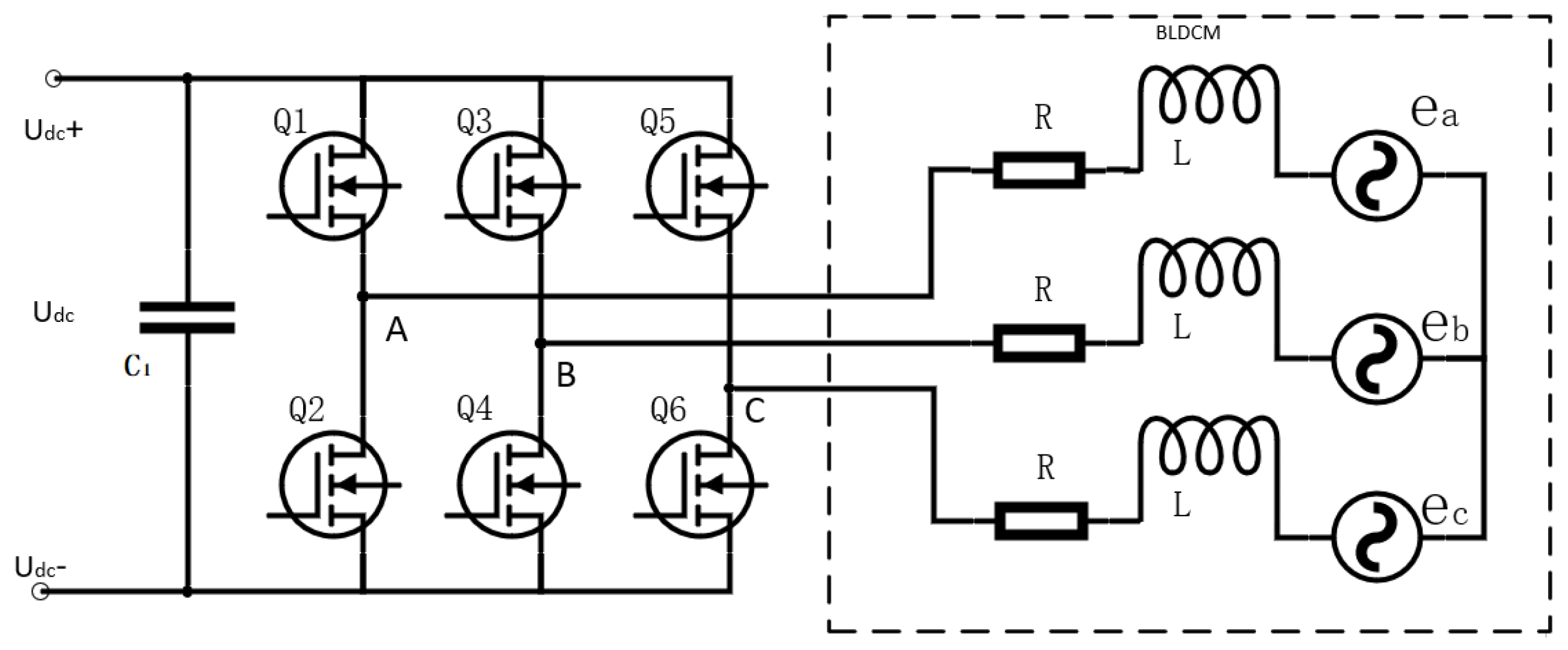
2. Inverter Circulating Current under Field Weakening of Permanent Magnet BLDCM

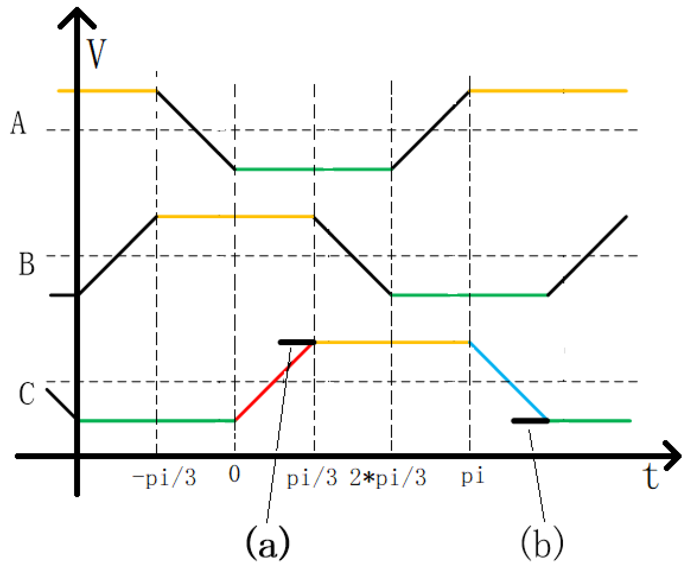
The Generation Mechanism of Field Weakening Inverter Circulation

A dedicated driver is required to operate a BLDCM, and its basic circuit configuration is typically shown in Figure 1. In Figure 1, U d c represents the power supply, which is connected to the U d c + and U d c − terminals of the DC bus. The driving buffer capacitor of the brushless motor is denoted as C 1 . The switch tubes Q1 to Q6, typically IGBT or MOSFET, form a three-phase AC bridge. The upper and lower contacts of the tube pairs are connected to the ABC three-phase terminals of the brushless motor. The internal structure of a three-phase motor includes the stator winding resistance R, stator winding inductance L, and back electromotive forces e a , e b , and e c during operation.
The stator winding of the motor functions as an inductive device, requiring a freewheeling path when it is turned off. As a result, the freewheeling diode becomes a necessary component for driving inductive loads. When weakening the motor’s field, it is important to consider the inverter’s circulating current caused by the freewheeling diode [15,16]. When performing field weakening speed regulation, the conduction angle of the BLDCM is advanced within the range of 0 to pi/3. Figure 2 shows the back EMF and field weakening characteristics of a brushless motor. During normal driving, the output voltage of the driver is in phase with the back EMF. In field weakening control, the non-conducting phase is advanced, and the conducting phase is terminated in advance. On the rising or falling edge of the non-conducting phase, different inverter circulating currents are generated. In Figure 2, these states are represented as state ‘a’ and state ‘b’. State ‘a’ corresponds to the conversion of B+A-CZ to C+A-BZ, where A phase is connected to U d c +, B phase is connected to U d c −, and C phase is not conducting. In the analysis that follows, phase C is considered the non-conducting phase, and the circulating currents resulting from the rising and falling edges of the back electromotive force are examined [17,18].
For star-connected three-phase windings, the BEMFs of the three phases are labeled as e a , e b , and e c , with the neutral point N having a voltage of 0. The direction of the BEMF is positive from the neutral point towards the head end and negative from the head end towards the midpoint. In the selected two phases, | e a | equals | e b |, and e c changes from e a to − e a and from − e a to e a , respectively. In terms of the electrical angle, this change process covers pi/3. Therefore, e c can be expressed using Formulas (1) and (2).
In state a of Figure 2, as the forward conduction angle increases, the back electromotive force decreases from ea along the red diagonal line to e a . The forward conduction angle, denoted as t, ranges from 0 to pi/3.
e c = e a + e a t p i / 6
In state b of Figure 2, as the forward conduction angle increases, the back EMF increases from e a to e a along the blue diagonal line. The forward conduction angle, denoted as t, ranges from 0 to pi/3.
e c = e a e a t p i / 6

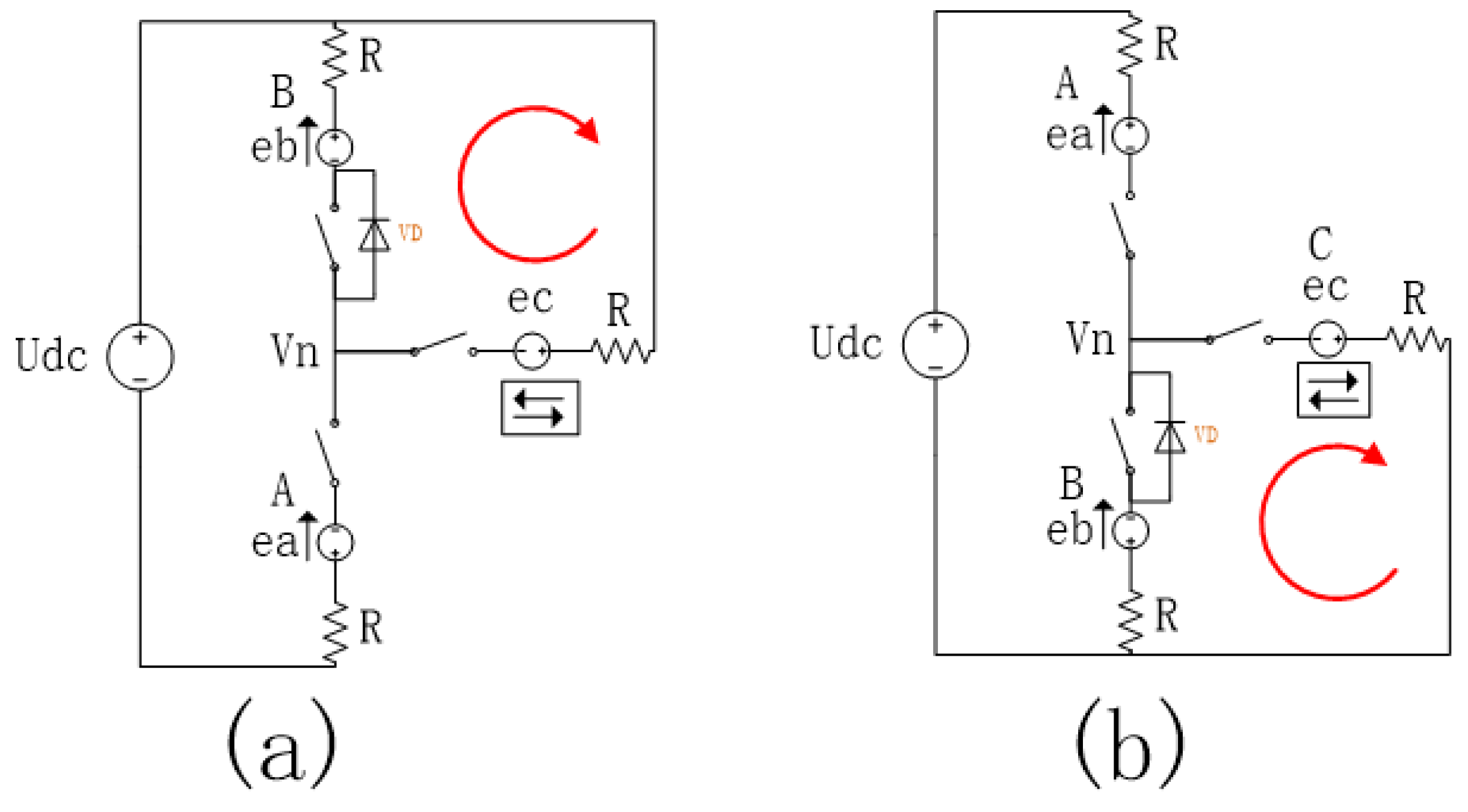
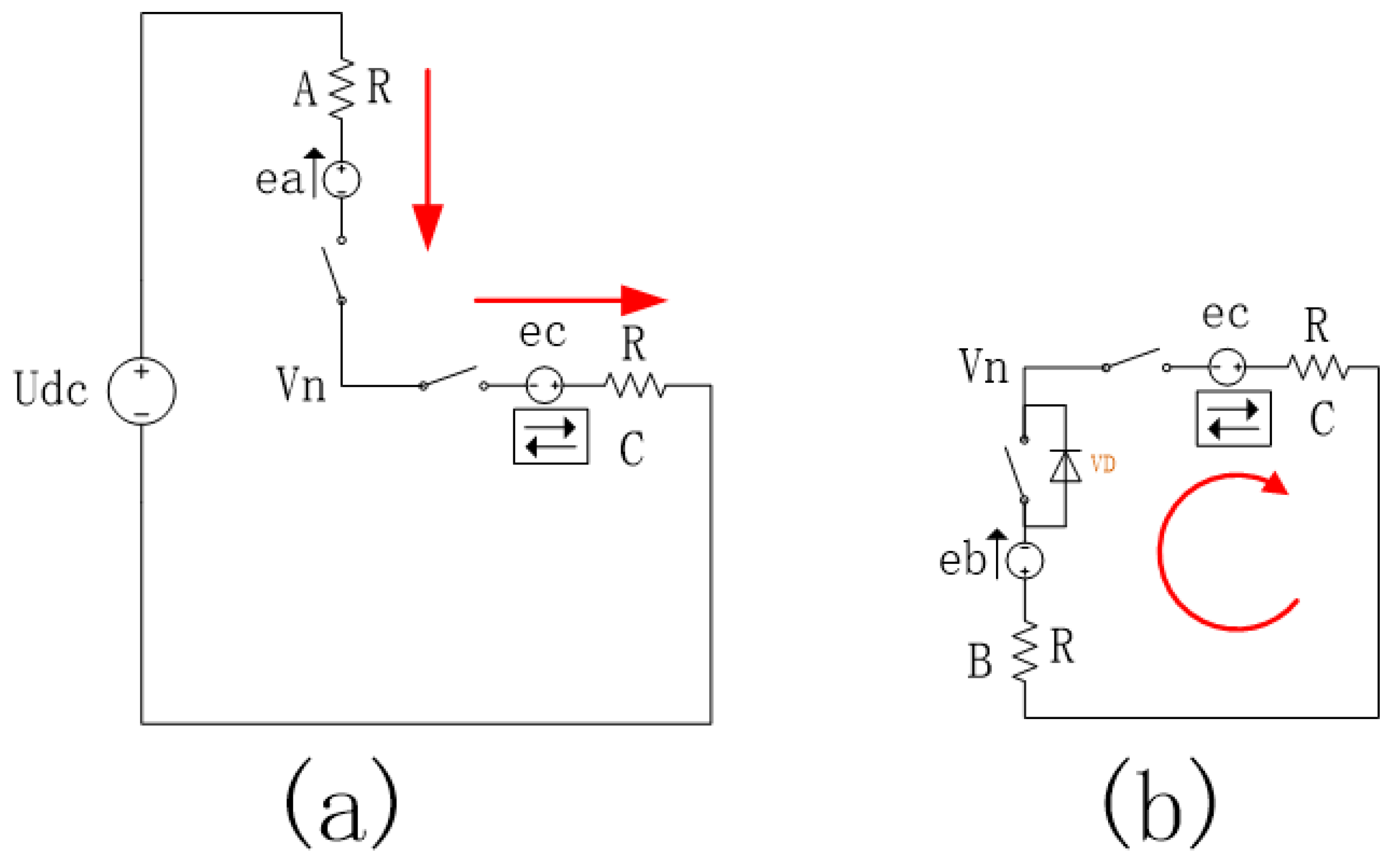
3. Further Analysis of Inverter Circulation

The inverter circuits corresponding to the back electromotive force shown in Figure 2, parts a and b, are illustrated in Figure 3. In Figure 3a, the winding B is connected to the positive pole of the DC power supply U d c , the winding A is connected to the negative pole, and the winding C is turned on in advance and connected to the positive pole. This configuration forms an inverter circulating current in the upper arm winding B, which flows through the winding B, the positive bus, the winding C, and the neutral point. In Figure 3b, the winding A is connected to the positive pole of the power supply U d c , the winding B is connected to the negative pole, and the winding C is turned on in advance and connected to the negative pole. This setup forms an inverter circulating current in the lower bridge arm winding B, which flows through the winding C, the negative bus, the winding B, and the neutral point. Within the range of 0 to pi/6 lead angle, in cases a and b, the upper bridge arm and lower bridge arm, respectively, exhibit circulating currents, and the freewheeling diode allows current to pass in the forward direction [19,20].
Based on Kirchhoff’s current theorem and a further analysis of the inverter circulation in Figure 3b, the circuit can be decomposed as shown in Figure 4.
Formula (3) lists the branch currents.
I a = U d c e a + e c 2 R I b = e c e b V d 2 R I c = ( I a + I b ) e b = e a e c = e a + e a t p i / 6
Formula (3) defines the used variables, where I a , I b , and I c represent the currents in the three-phase winding; V d represents the voltage drop across the freewheeling diode conduction tube; V n represents the neutral point voltage; R represents the equal three-phase winding resistance; e a and e b represent the back electromotive force of the three-phase winding, with | e a |=| e b |; and t represents the leading conduction angle, ranging from 0 to pi/3. By eliminating the neutral point voltage Vn from Formulas (1)–(3), Formula (4) for the three-phase currents I a , I b , and I c is derived.
I a = ( U d c 2 e a ) + e a t p i / 6 2 R I b = e a t p i / 6 V d 2 R I c = ( U d c 2 e a ) + 2 e a t p i / 6 V d 2 R
By examining Formulas (3) and (4), it can be deduced that the condition for generating inverter circulating current is when e c e b > V d . An experimental verification of the inverter circulating current is conducted based on the aforementioned formula. The used motor has four pole pairs, a power supply voltage of 14 V, and is operated under no load conditions. When the field weakening angle is set to pi/6, the average running current is approximately 0.8 A, and the speed reaches around 3950 rpm. The presence of inverter circulation in the motor winding is observed, as depicted in Figure 5. In Figure 5, the yellow line in channel 1 represents the stator current measured by the current probe, while the other three channels display the voltage signals of the three-phase stator: blue indicates the voltage of the current phase, while purple and green represent the phase voltages of the other two phases. The white circle corresponds to the reverse inverter circulating current caused by the positive connection of the green phase in Channel 4 to the busbar in advance, whereas the red circle corresponds to the inverter circulating current resulting from the negative connection of the green phase in Channel 4 to the busbar in advance.

4. The Combined Magnetic Potential Analysis of the Inverted Circulating Current and the Early Conduction

4.1. Derive the Resultant Magnetic Potential Generated by the Current from the Three-Phase Current

In the given formula definition, the angle between the three-phase currents I a , I b , and I c is evenly distributed at 120 degrees. Neglecting the influence of the rotor magnetic potential, the composite magnetic potential F f of the three-phase current can be represented by Formula (5):
F f = 2 I a + I b + I c 2 i + s q r t 3 2 ( I b + I c ) j
By substituting Formula (4) into Formula (5), we obtain Formula (6):
F f = 3 2 ( U d c 2 e a ) + e a t p i / 6 2 R i s q r t 3 2 ( U d c 2 e a ) + 3 e a t p i / 6 2 R j
The angle of F f can be expressed as Formula (7):
θ = a t a n ( F f j F f i ) = a t a n 1 s q r t 3 ( U d c 2 e a ) + e a t p i / 6 ( U d c 2 e a ) + 3 e a t p i / 6
Analyzing Formula (7), the magnitude of the magnetic potential synthesized by the inverter circulating current is related to the back electromotive force ea, the weak magnetic lead angle t, and the diode conduction voltage drop V d . The back EMF has the greatest impact. When the back EMF satisfies U d c = 2 e a , the magnetic force direction θ formed by the circulating current is the most advanced. When the back EMF is 0, the magnetic force angle is close to 0. The weak magnetic lead angle and the voltage drop of the diode pass tube have little effect.

4.2. The Influence of the Circulation on the Resultant Magnetic Potential

Figure 6a illustrates the direction of the magnetic potential during the commutation of a permanent magnet brushless motor, assuming the reverse conversion flow is not considered. In this figure, the magnetic potential of the rotor is represented by Ff, with a direction of pi/2. The conduction state of the MOS tube in the drive bridge transitions from A+B- to A+C-, causing the magnetic potential to switch from the combined magnetic potential of phase A and phase B (Fa+b) to the resultant magnetic potential of phase A and C (Fa+c-). The direction of Fa+b- is 5 pi/6, while the direction of Fa+c- is 7 pi/6, resulting in an angle of pi/3 between the two potentials. During normal commutation, the angle between the stator magnetic potential and the rotor magnetic potential changes from pi/3 to pi*2/3, allowing for the continuous rotation of the rotor. In the current field weakening control algorithm, it is considered that the direction of the composite magnetic potential remains unchanged and is solely dependent on the state of the switch tube, serving as the output angle of the field weakening control [21].
Figure 6b depicts a schematic diagram of the synthetic magnetic potential generated by adding the circulating current. Based on Formulas (8) and (9), it can be deduced that the resulting synthetic magnetic potential closely resembles the magnetic potential generated by the C phase alone, as illustrated by the red vector Fh1 in Figure 6b. The resultant magnetic potential is influenced by the lead angle, with a larger lead angle bringing it closer to the phase C position. As the rotor moves, the inverter’s circulating current gradually diminishes, causing the resultant magnetic potential to rotate counterclockwise towards the direction of the AC phase resultant magnetic potential Fa+c-. Eventually, it settles at the Fa+c- position after the field weakening process, as demonstrated in Figure 6b, represented by the gray dotted line.

4.3. The Field Weakening Effect and Braking Effect of the Inverter Circulation

When considering the absence of circulation, the resulting magnetic potential is a combination of phase A and phase C, with its direction pointing to the 7*pi/6 position. Permanent magnet brushless motors undergo commutation at intervals of pi/3. Hence, if the field weakening angle is less than pi/3, it only amplifies the degree of field weakening without triggering a reverse braking effect. As depicted in Figure 7a, the solid line Ff represents the position of the rotor magnetic potential without field weakening, while the dashed line Ff’ represents the relative backward position of the rotor magnetic potential when the weak magnetic field advances by pi/3. In this scenario, the driving magnetic potential is leading the rotor magnetic potential by pi, resulting in no generation of driving torque or braking torque.
When considering the circulation, the resulting magnetic potential undergoes forward drift and falls between 7 pi/6 and 8 pi/6. Greater circulation brings the magnetic potential closer to the direction of 8*pi/6, as depicted in Figure 7b. In the presence of the composite magnetic potential Fhl, field weakening may exceed pi/6. Once the composite magnetic potential Fhl leads the rotor magnetic potential Ff’ by a pi angle, the motor generates a braking effect, which diminishes after the rotor completes a certain rotation. This braking effect arises from the circulating current, leading to increased power consumption as well as reduced torque and efficiency of the motor [22].
Using Formula (7), the angle between the stator magnetic potential and the phase A magnetic potential can be calculated. In Figure 6, the angle between the phase A magnetic potential and the rotor magnetic potential is pi/2. Hence, the angle between the rotor magnetic potential and the stator magnetic potential can be expressed as Equation (8). However, without the specific content of these formulas, it is difficult to provide further analysis or clarification.
θ 2 = p i / 2 + θ
The angle of θ 2 is related to the magnitude of the back-EMF e a and the forward voltage drop of the freewheeling diode V d . When V d = 0.4 V, the relationship between θ 2 and e a and t can be drawn, and the following Figure 8 can be obtained:
Figure 8 shows that when the field weakening angle exceeds pi/6 (30 degrees), θ 2 will be greater than pi, that is, the stator magnetic potential leads the rotor magnetic potential by 180 degrees, and the braking effect appears; Figure 8 also shows that the magnitude of the back EMF is opposite to that of the variable circulating current has an effect. The closer the back EMF is to 1/2 of the power supply voltage, the earlier the braking effect appears.

5. Matlab Simulation Model and Result Verification

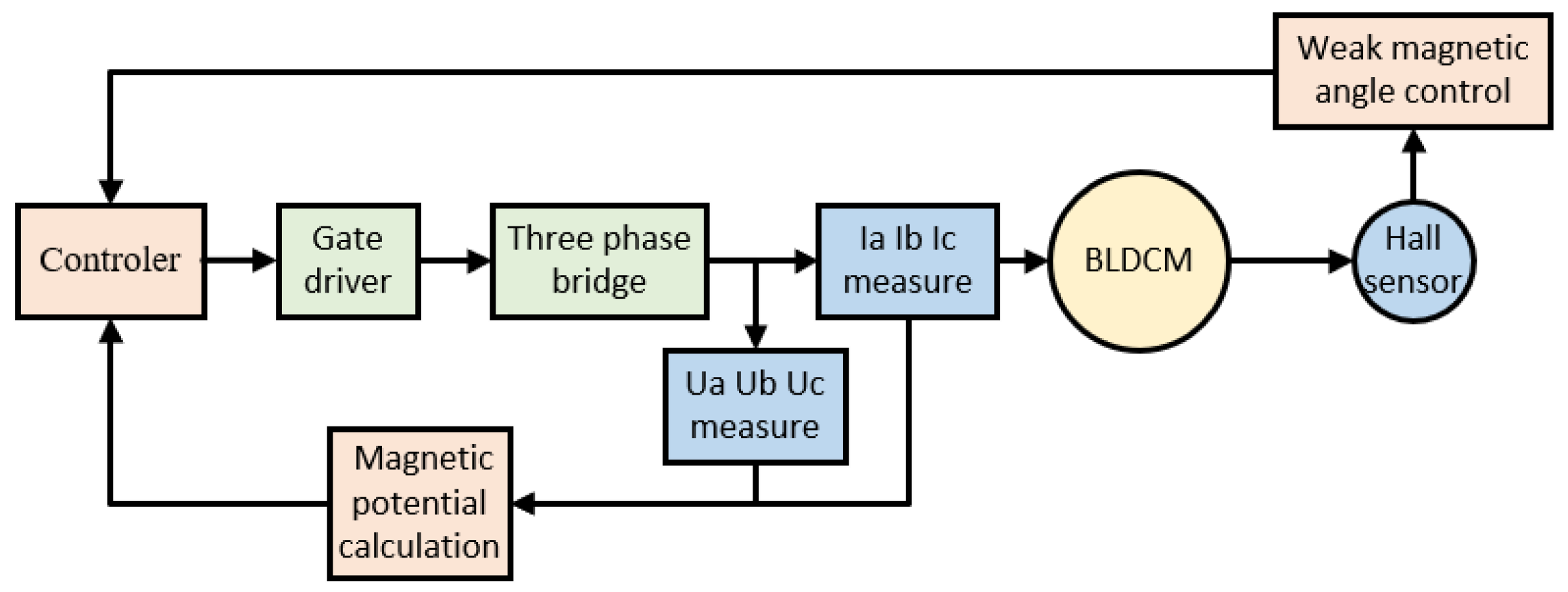
5.1. Simulation Model

We have verified the theoretical derivation presented in the previous section of this article using the software MATLAB R2019a. We utilized the MATLAB sample ‘Brushless DC Motor Fed by Six-Step Inverter’ and made modifications by adding the weak magnetic adjustment module and the synthetic magnetic potential calculation. The model of the module is shown in Figure 9.
The results of the model operation align with the formula derivation in Section 4. When the field weakening angle is within the range of pi/11 to pi/3, an evident reverse circulating current can be observed, and the resultant magnetic potential precedes the weak magnetic potential when no circulating current is present.
The unmodified sample model parameters were set as follows: input speed—4000 (exceeding the motor base speed), voltage source—500 V, and motor torque—T = 5. The motor is driven using a six-step method. Due to the influence of stator inductance, the current exhibits an upward trend after being turned on [23]. Figure 10 displays the current waveforms for two complete cycles.The calculation of the composite magnetic potential follows Formula (5). In Figure 10, the direction of the composite magnetic potential is represented by the angle of the magnetic potential (red line). The angles are respectively pi/6, pi/2, 5 pi/6, 7 pi/6, 3 pi/2, and 11 pi/6. It can be observed that the magnetic potential remains a horizontal straight line during each conduction phase, indicating a constant direction. The phase is commutated at every pi/3 electrical angle, and the magnetic potential advances by pi/3 [24].

5.2. The Sample Model Is Modified to Field Weakening Control and Operating Results

The modification of the sample model is divided into two parts:

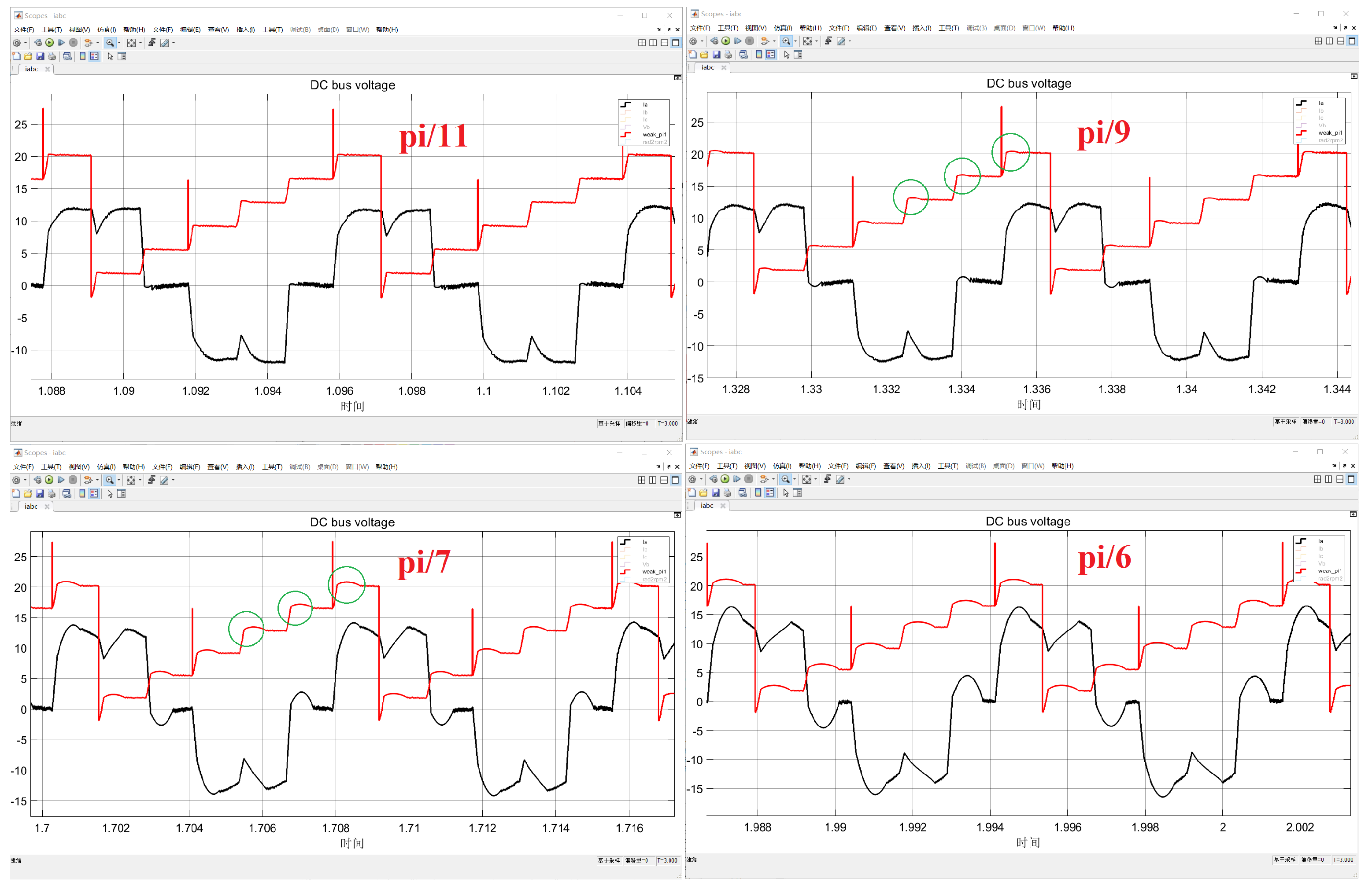
5.2.1. Change of Field Weakening Angle

(1) Lead the rotor angle <Rotor angle thetam> from the motor;
(2) Adjust the number of magnetic pole pairs by setting the gain to 4;
(3) Incorporate the field weakening angle and calculate the sum;
(4) Obtain the current electrical angle by performing the remainder operation of 2*pi;
(5) Calculate the electrical angle within the range of pi/3 to determine the current phase of the 6-step drive.

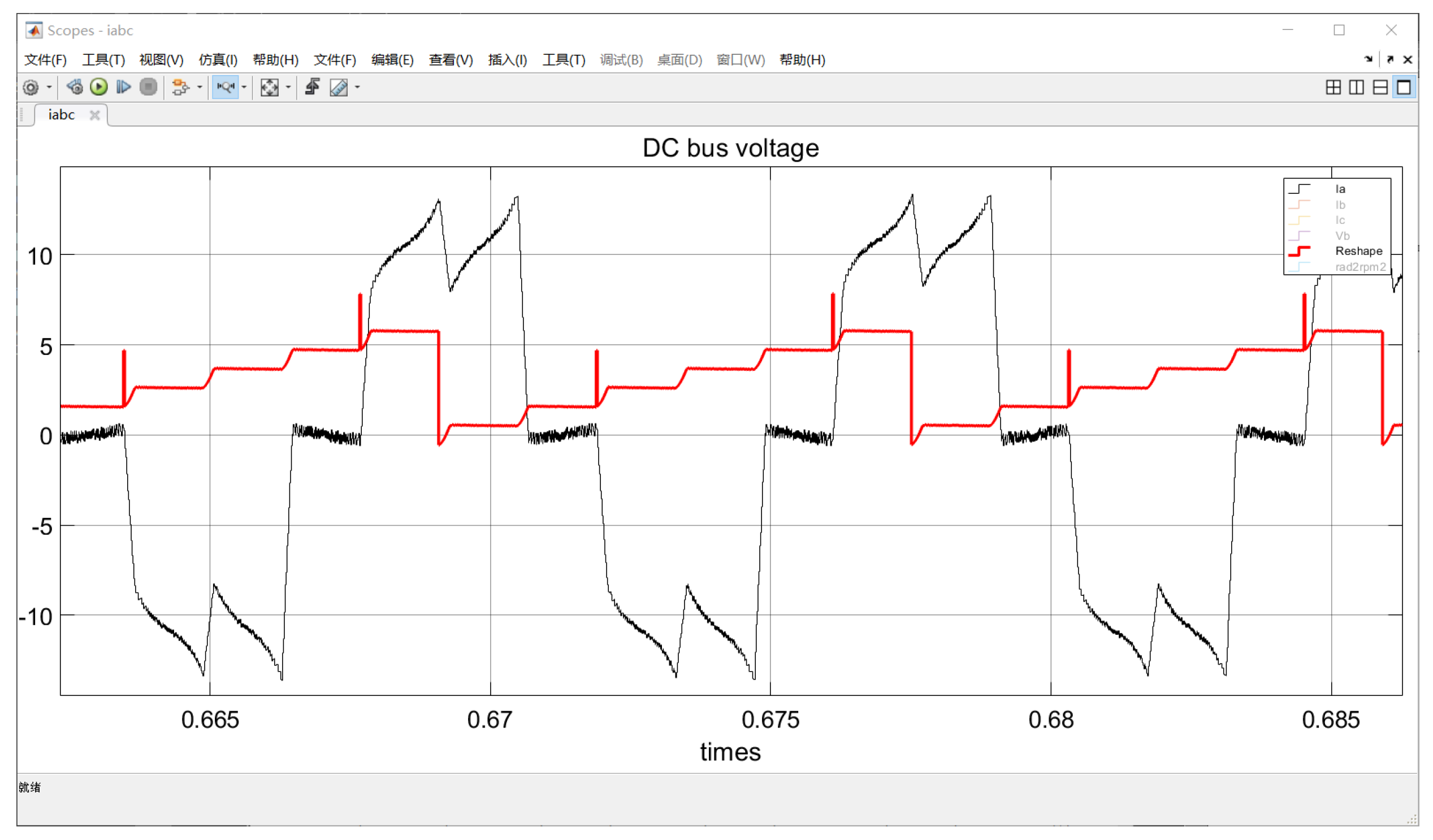
5.2.2. Solving the Magnetic Potential

The direction of the magnetic potential in the driving coil is calculated based on the three-phase current and the current driving angle. This calculation can be divided into two parts:
(1) Collect the three-phase current and perform a Clark transformation to convert it into Fx and Fy components in the static coordinate system.
(2) Convert Fx and Fy into Ff and observe the image using an oscilloscope. Figure 11 shows the single-phase current waveform and the synthesized magnetic potential collected by the oscilloscope module in Simulink under different field weakening angles. As the field weakening angle increases from pi/11 to pi/6, both the amplitude and width of the inverter circulation increase [25,26,27]. Additionally, a noticeable transformation into a composite magnetic potential can be observed.
In Figure 11, the green circle indicates the initiation of each phase as a weak magnetic field. The reverse circulating current generated in this region causes the forward movement of the weak magnetic field. As the field weakening angle increases, the amplitude of the composite magnetic potential moving forward also increases. When the field weakening angle approaches pi/6, the magnetic potential moves forward close to pi/6.

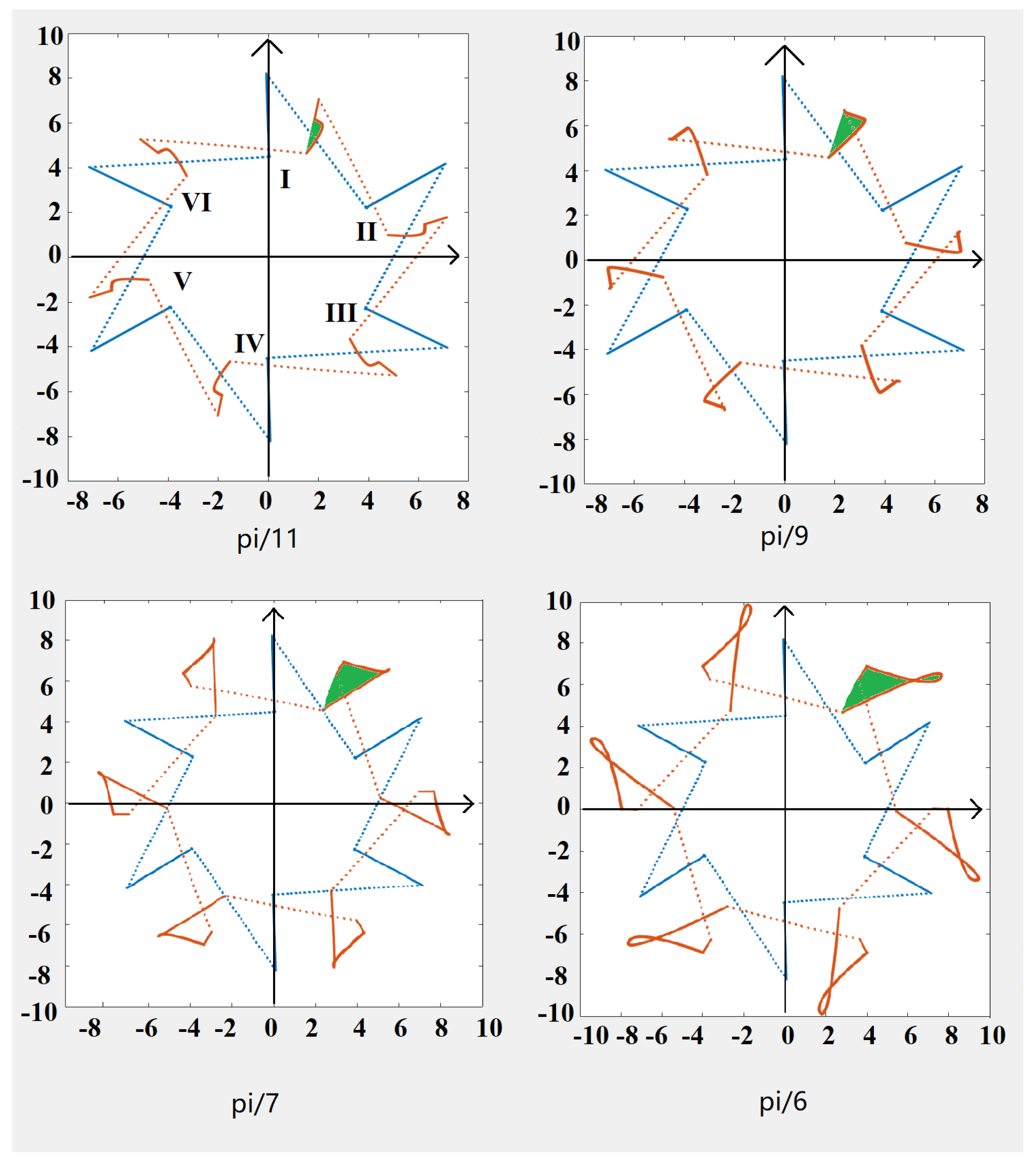
6. Analysis of Magnetic Potential Trajectory

When observing the F x and F y images on the oscilloscope in Simulink, each cycle is independent, making it difficult to make a direct comparison. To visualize the magnetic potential trajectory, the magnetic potential angle is calculated using Formula (5). Furthermore, a MATLAB script is used to rotate and translate the coordinates based on the synchronization parameters of the weak magnetic and electrical angles. The magnetic potential trajectory points are redrawn using the converted coordinates as per Formula (9).
A = c o s ( a ) s i n ( a ) s i n ( a ) c o s ( a ) P = [ F x , F y ] Q = P A
In Figure 12, the dashed line represents the resultant magnetic potential during commutation. Due to the shorter simulation step length compared with the commutation time, the dashed line appears multiple times. The solid line depicts the variation of the magnetic potential within a specific phase. The blue solid line represents the magnetic potential trajectory without field weakening during normal commutation. The brown solid line illustrates the magnetic potential trajectory with field weakening. The green area indicates the influence of the inverter circulation on the combined magnetic potential and the swept region by the magnetic potential.
The six-angle image of the blue line corresponds to the six magnetic potential directions in the 6-step commutation method. The winding inductance causes a gradual increase in current [28,29], and the magnitude of the magnetic potential increases without changing its direction. By analyzing the green area, it can be observed that when the field weakening angle is less than pi/6, the magnetic potential moves forward in the direction of motor rotation. The brown curve demonstrates that as the motor rotor exits the field weakening zone, the inverter circulating current gradually decreases and disappears, and the magnetic potential returns to its position without field weakening. As the field weakening angle increases, the amplitude of the forward movement of the magnetic potential also increases [30,31].
When the field weakening angle is less than pi/6, the generated magnetic potential moves forward without causing the rotor to rotate 180 degrees. This enhancement of the weak magnetic effect does not result in a braking effect. However, when the field weakening angle exceeds pi/6, the amplitude of the composite magnetic potential moving forward continues to increase.
In Figure 13, with a leading excitation angle of pi/5 and the rotor position marked as the black diagonal line ‘fa’, the normal driving phase magnetic potential is indicated by the blue direction within the red circle. As depicted in Figure 13, at pi/5, the trajectory of the synthesized magnetic potential is represented by the brown line, which aligns with the normal driving phase magnetic potential. A small portion of the synthesized magnetic potential (green area) exceeds the rotor’s pi angle, resulting in a braking effect on the motor.

7. Conclusions

In the field weakening control process of a BLDCM, leading conduction results in a voltage higher than the power supply during motor operation. This, in turn, generates inverter circulating current in the freewheeling diode, MOSFET, and stator winding. The circulating current of the inverter influences the direction of the combined magnetic potential, causing it to move forward in the direction of rotor rotation. When the field weakening angle is within the range of 0 to pi/6, the inverter current cycle movement is less than pi/6. This leads to a weak magnetic field and contributes to the driving function. However, when the field weakening angle falls between pi/6 and pi/3, the inverter current circulation range exceeds pi/6. This has the effect of both a weak magnetic field and braking, resulting in a decrease in motor torque and efficiency. Based on previous research and analysis, it is recommended that the field weakening range for BLDCMs be between 0 and pi/6.

Author Contributions

Conceptualization, X.L. and S.W.; methodology, X.L.; writing—original draft preparation, X.L.; writing—review and editing, L.X.; supervision, L.X. All authors have read and agreed to the published version of the manuscript.

Funding

This research was funded by Key research and development Plan of Shandong Province (2022), grant number: 2022CXGC020307.

Data Availability Statement

No new data were created or analyzed in this study. Data sharing is not applicable to this article.

Conflicts of Interest

The authors declare no conflict of interest.

References

  1. Xia, C.; Fang, H. Permanent-Magnet Brushless DC Motor and Its Control. Trans. China Electrotech. Soc. 2012, 27, 25–34. [Google Scholar]
  2. Chu, K.S.K.; Chew, K.W.; Chang, Y.C. Fault-Diagnosis and Fault-Recovery System of Hall Sensors in Brushless DC Motor Based on Neural Networks. Sensors 2023, 23, 4330. [Google Scholar] [CrossRef] [PubMed]
  3. Du, J.; Li, C.; Zhao, J.; Ren, H.; Zhang, K.; Song, X.; Chen, L.; Yu, S.; Mi, Y. Investigation of Eddy Current Loss and Structure Design with Magnetic-Thermal Coupling for Toothless BLDC High-Speed PM Motor. Machines 2022, 10, 118. [Google Scholar] [CrossRef]
  4. Udayakumar, A.K.; Raghavan, R.R.V.; Houran, M.A.; Elavarasan, R.M.; Kalavathy, A.N.; Hossain, E. Three-Port Bi-Directional DC–DC Converter with Solar PV System Fed BLDC Motor Drive Using FPGA. Energies 2023, 16, 624. [Google Scholar] [CrossRef]
  5. Zhang, Z.; Li, Y. An AEFA-Based Optimum Design of Fuzzy PID Controller for Attitude Control Flywheel with BLDC Motor. Aerospace 2022, 9, 789. [Google Scholar] [CrossRef]
  6. Jeon, K.; Yoo, D.; Park, J.; Lee, K.-D.; Lee, J.-J.; Kim, C.-W. Reliability-Based Robust Design Optimization for Maximizing the Output Torque of Brushless Direct Current (BLDC) Motors Considering Manufacturing Uncertainty. Machines 2022, 10, 797. [Google Scholar] [CrossRef]
  7. Ustun, O.; Kivanc, O.C.; Senol, S.; Fincan, B. On Field Weakening Performance of a Brushless Direct Current Motor with Higher Winding Inductance: Why Does Design Matter? Energies 2018, 11, 3119. [Google Scholar] [CrossRef]
  8. Fang, H.; Xia, C.; Fang, Y. Position servo control of brushless DC motor based on the second discrete filter. Proc. CSEE 2009, 29, 65–70. [Google Scholar]
  9. Zhang, F.; Du, G.; Wang, T.; Liu, G. Review on development and design of high speed machine. Trans. China Electrotech. Soc. 2016, 31, 1–18. [Google Scholar]
  10. Lai, Y.-S.; Lin, Y.-K. A Unified Approach to Zero-Crossing Point Detection of Back EMF for Brushless DC Motor Drives without Current and Hall Sensors. IEEE Trans. Power Electron. 2011, 26, 1704–1713. [Google Scholar] [CrossRef]
  11. Liu, W.; Li, R. Research on flux weakening mechanism of rare earth PMBLDCM. J. Northwestern Polytech. Univ. 2007, 25, 662–666. [Google Scholar]
  12. Matsui, N.; Takeshita, T.; Yasuda, K.A. New sensorless drive of brushless DC motor (VIEW record in Inspec). In Proceedings of the 1992 International Conference on Industrial Electronics, Control, Instrumentation, and Automation, San Diego, CA, USA, 9–13 November 1992; Volume 1–3, pp. 430–435. [Google Scholar]
  13. Tan, B.; Liu, W.-G.; Ma, R.-Q.; Zhao, J. Study on speed regulation of BLDCM with weak magnetic field. Small Spec. Electr. Mach. 2009, 12, 15–18. [Google Scholar]
  14. Li, R.; Liu, W.; Liu, X.; Liu, J. Analysis of Flux-Weakening by Eliminating Circulating Current in PM BLDCM. Trans. China Electrotech. Soc. 2007, 22, 62–67. [Google Scholar]
  15. Ha, J.I.; Ide, K.; Sawa, T.; Sul, S.K. Sensorless rotor position estimation of an interior permanent-magnet motor from initial states. IEEE Trans. Ind. Appl. 2003, 39, 761–767. [Google Scholar]
  16. Gałuszkiewicz, P.; Gałuszkiewicz, Z.; Baran, J. Simulation Studies of Energy Recovery in a BLDC Motor-Based Kinetic Energy Storage. Energies 2022, 15, 7494. [Google Scholar] [CrossRef]
  17. Gamazo-Real, J.C.; Vázquez-Sánchez, E.; Gómez-Gil, J. Position and Speed Control of Brushless DC Motors Using Sensorless Techniques and Application Trends. Sensors 2010, 10, 6901–6947. [Google Scholar] [CrossRef]
  18. Lee, K.-W.; Kim, D.-K.; Kim, B.-T.; Kwon, B.I. A novel starting method of the surface permanent-magnet BLDC motors without position sensor for reciprocating compressor. IEEE Trans. Ind. Appl. 2008, 44, 85–92. [Google Scholar] [CrossRef]
  19. Wang, Z.; Lu, K.; Blaabjerg, F. A Simple Startup Strategy Based on Current Regulation for Back-EMF-Based Sensorless Control of PMSM. IEEE Trans. Power Electron. 2012, 27, 3817–3825. [Google Scholar] [CrossRef]
  20. Lai, Y.-S.; Lin, Y.-K.; Chen, C.-W. New Hybrid Pulsewidth Modulation Technique to Reduce Current Distortion and Extend Current Reconstruction Range for a Three-Phase Inverter Using Only DC-link Sensor. IEEE Trans. Power Electron. 2013, 28, 1331–1337. [Google Scholar] [CrossRef]
  21. Chun, T.-W.; Tran, Q.-V.; Lee, H.-H.; Kim, H.G. Sensorless Control of BLDC Motor Drive for an Automotive Fuel Pump Using a Hysteresis Comparator. IEEE Trans. Power Electron. 2014, 29, 1382–1391. [Google Scholar] [CrossRef]
  22. Shao, J.W.; Nolan, D.; Teissier, M.; Swanson, D. A novel microcontroller-based sensorless brushless DC (BLDC) motor drive for automotive fuel pumps. IEEE Trans. Ind. Appl. 2003, 39, 1734–1740. [Google Scholar] [CrossRef]
  23. Kang, Y.; Lee, S.B.; Yoo, J. A microcontroller embedded AD converter based low cost sensorless technique for brushless DC motor drives. In Proceedings of the Conference Record of the 2005 IEEE Industry Applications Conference, Kowloon, Hong Kong, 2–6 October 2005; Volume 1–4, pp. 2176–2181. [Google Scholar]
  24. Lee, K.W.; Hong, J.; Lee, S.B.; Lee, S. Quality Assurance Testing for Magnetization Quality Assessment of BLDC Motors Used in Compressors. IEEE Trans. Ind. Appl. 2010, 46, 2452–2458. [Google Scholar] [CrossRef]
  25. Jahns, T.M. Flux-weakening regime operation of an interior permanent-magnet synchronous motor drive. IEEE Trans. Ind. Appl. 1987, 23, 681–689. [Google Scholar] [CrossRef]
  26. Ionel, D.M.; Balchin, M.J.; Eastham, J.F.; Demeter, E. Finite element analysis of brushless DC motors for flux weakening opreration. IEEE Trans. Magn. 1996, 32, 5040–5042. [Google Scholar] [CrossRef]
  27. Zhu, Z.Q.; Shen, J.X.; Howe, D. Flux-weakening characteristics of trapezoidal back-EMF machines in brushless DC and AC modes. In Proceedings of the CES/IEEE 5th International Power Electronics and Motion Control Conference, Shanghai, China, 14–16 August 2006; p. 908. [Google Scholar]
  28. Krishnan, R. Permanent Magnet Synchronous and Brushless DC Motor Drives; Taylor & Francis Group Thames: London, UK, 2010. [Google Scholar]
  29. Lee, D.-M.; Lee, W.-C. Analysis of Relationship Between Abnormal Current and Position Detection Error in Sensorless Controller for Interior Permanent-Magnet Brushless DC Motors. IEEE Trans. Magn. 2008, 44, 2074–2081. [Google Scholar]
  30. Guglielmi, P.; Pastorelli, M.; Vagati, A. Cross-saturation effects in IPM motors and related impact on sensorless control. IEEE Trans. Ind. Appl. 2006, 42, 1516–1522. [Google Scholar] [CrossRef]
  31. Li, J.; Liu, G.; Jia, H.P. Flux-weakeing control of Permanent Magnet Brushless DC Motor Used in E-bike. J. Nanjing Univ. Sci. Technol. (Nat. Sci.) 2009, 33, 76–80. [Google Scholar]
Figure 1. Schematic diagram of BLDCM and driver.
Electronics 12 02450 g001
Figure 2. BEMF of BLDC, (a) corresponds to the conversion of B+A-CZ to C+A-BZ, (b) corresponds to the conversion of A+B-CZ to A+C-BZ.
Electronics 12 02450 g002
Figure 3. Inverter circulating current of upper and lower arms. (a) represents the winding B is connected to the positive pole of the DC power supply, (b) represents the winding A is connected to the positive pole of the power supply.
Electronics 12 02450 g003
Figure 4. Decomposition of freewheeling circuit. (a) represents the current generated by voltage sources U d c , BEMF e a , and e c in windings A and C, (b) represents the current generated by the B phase freewheeling current, BEMF e b , and e c in the windings B and C.
Electronics 12 02450 g004
Figure 5. The freewheeling current of flux-weakening.
Electronics 12 02450 g005
Figure 6. Analysis of magnetic potential generated by inverter circulating current. (a) illustrates the direction of the magnetic potential during the commutation of a permanent magnet brushless motor, (b) depicts a schematic diagram of the synthetic magnetic potential generated by adding the circulating current.
Electronics 12 02450 g006
Figure 7. Braking effect of inverter circulating current. (a) indicates the position of the rotor magnetic potential without field weakening, (b) indicates the braking effect arises from the circulating current.
Electronics 12 02450 g007
Figure 8. Weak magnetic angle and the Angle between magnetic potential of stator and rotor.
Electronics 12 02450 g008
Figure 9. Matlab simulation model.
Electronics 12 02450 g009
Figure 10. The phase current and magnetic potential of simulation model.
Electronics 12 02450 g010
Figure 11. The phase current distortion and weak magnetic potential.
Electronics 12 02450 g011
Figure 12. Magnetic potential distortion caused by inverter circulating current.
Electronics 12 02450 g012
Figure 13. Braking effect caused by phase current distortion.
Electronics 12 02450 g013
Disclaimer/Publisher’s Note: The statements, opinions and data contained in all publications are solely those of the individual author(s) and contributor(s) and not of MDPI and/or the editor(s). MDPI and/or the editor(s) disclaim responsibility for any injury to people or property resulting from any ideas, methods, instructions or products referred to in the content.

