Abstract
A new concept of global navigation based on Doppler measurements from a large low Earth orbit (LEO) constellation is investigated that has potential to serve as a complement or backup to global navigation satellite systems (GNSSs) to provide navigation and positioning services in GNSS denial environments. In this work, we investigate the potential of LEO communication satellite opportunity signals in dynamic navigation, establish LEO satellite Doppler positioning equations, derive the main error sources affecting the Doppler positioning results of a dynamic target, and analyze the impact of each error source on positioning accuracy through a simulation. The results show that the orbit error and clock drift had a large impact on positioning accuracy. This navigation scheme would be more competitive if it could provide high-precision satellite orbits and accurate Doppler measurements. The obtained results show that the LEO satellite signals used as navigation opportunity signals are an attractive alternative in GNSS rejection environments for high dynamic targets.
1. Introduction
GNSSs have become the most widely used navigational method, providing users with position- and navigation-timing (PNT) services in various application scenarios. However, with the wide application of GNSSs, some of their problems, such as low signal power, poor satellite visibility, and susceptibility to electromagnetic interference, have been exposed. Therefore, an increasing number of experts and scientists are attempting to find new navigation methods to improve or replace GNSSs, and the LEO satellite is one of the most popular topics.
LEO satellites have many advantages over GNSSs. For example, signals from LEO satellites are received with higher power and lower delay compared to GNSSs. In addition, the number of LEO satellites is much higher than that of GNSSs, and their signals are spatially and spectrally diverse. Positioning with LEO satellites concerns navigation using signals of opportunity (SOPs). SOPs are radio frequency signals that are not intended for navigational purposes. The disadvantage of SOPs is that the signals are not optimized for navigational purposes. This means that the signal structure may not be fully known, signals from different transmitters (even from the same system) are not synchronized in time, their clock stability is lower than that of GNSS satellites, and the transmitter positions are unknown [1,2,3].
Research into the use of LEO satellites for positioning began many years ago, but was limited by the technology and the number of LEO satellites. The technology of satellite launching and networking is maturing, with companies such as Amazon, OneWeb, and SpaceX deploying so-called mega-LEO satellites to provide global broadband Internet. In particular, launching thousands of satellites into LEO by SpaceX is a turning point for the future of LEO-based navigation technologies [4,5,6,7].
In this paper, we study the potential of the LEO satellites signals for the navigation of a dynamic target using simulated Starlink satellites as an example. Starlink is a giant constellation of LEO satellites designed and launched by SpaceX to provide satellite Internet services to users around the world. SpaceX has launched thousands of Starlink satellites.
Navigation using LEO satellites signals as SOPs has been the focus of many papers. In 2021, the authors in [8] proposed a blind Doppler tracking and beacon detection algorithm for opportunistic navigation with LEO satellite signals. In [9], the authors proposed an algorithm to track blind doppler OFDM signals transmitted by broadband LEO satellites. The authors in [10] realized localization by using a carrier-phase tracking algorithm based on an adaptive Kalman filter with the 11.325 GHz pilot signal of the Starlink satellite. The experimental results showed that its horizontal positioning error was 25.9 m by using the data of six Starlink satellites with a total duration of 800 s. In [11], the authors proposed a matching subspace detection method to extract frequency information. The authors in [12] used extracted frequency information for Doppler positioning, and the horizontal positioning accuracy reached 10 m.
Most of the studies on LEO satellite navigation and positioning in the above literature have been about geostationary target positioning or a fusion with inertial guidance for motion target navigation. In this paper, we construct Doppler positioning equations for LEO satellite opportunity signals, and propose a method for solving motion target positions using only the Doppler shift of LEO satellite opportunity signals and not relying on other auxiliary means such as inertial guidance.
In this paper, we analyze the potential of LEO satellites for motion target navigation, construct Doppler localization equations, and analyze and verify through simulation the effect of various error sources on localization accuracy during navigation. This paper is organized as follows. Section 2 analyzes the satellite orbit and the Doppler model. Section 3 proposes the methods of Doppler positioning with LEO satellites for dynamic targets based on stationary targets. Section 4 outlines the simulation of the Doppler navigation process of an aircraft using the opportunistic signals of six Starlink satellites, and analyzes the influence of various error sources on the navigation results. Section 5 concludes the paper.
2. Satellite Orbit and Doppler Model
2.1. LEO Satellite Orbit Model
Since the real orbit of an LEO satellite is difficult to be measured and obtained in real time, the predicted orbit, obtained by substituting open two-line orbital element (TLE) data into the SGP4 model, is regarded as the satellite orbit [13].
TLE data are the most commonly used satellite orbit data in the world; they were designed and developed by North American Aerospace Defense Command (NORAD), a joint military organization of the United States and Canada. Once in space, satellites, spacecraft, and aircraft are listed in the NORAD satellite ephemeris catalog. Objects listed in the NORAD ephemeris are tracked for life. NORAD regularly releases the latest TLE data [14].
TLE contains the six orbital parameters of Kepler’s law. It only needs to plug TLE data into the official SGP4 orbital prediction model to calculate past or future satellite positions.
However, the predicted orbits using TLE data and the SGP4 model are not representative of real satellite orbits. There are errors between the predicted and real satellite orbits, and errors increase with time. Until the latest updated TLE data are obtained, errors in the predicted orbits can reach the kilometer level and are mainly concentrated in the tangential direction [15].
The LEO satellite orbit error curve is approximated as a quadratic function [15], and the predicted orbit error model is as follows:
where is the prediction time in seconds, is the standard deviation of the orbit prediction error in meters, and , , and are the constant, linear, and quadratic terms of the quadratic fitting coefficient, respectively.
2.2. Doppler Shift Model
The Doppler frequency is the frequency variation characteristic of any electromagnetic signal with relative motion between objects. The LEO satellite signal receiver mounted onto a highly dynamic vehicle produces Doppler frequency measurements on the available LEO satellite signals [16], which can be modeled as follows:
where is the range rate, is the carrier frequency, and c is the light speed.
Doppler shift measurements are affected by many error sources, including ionospheric and tropospheric delays, transmitter and receiver clock errors, and multipath effects on the signal. For vehicles travelling in the open sky, multipath errors are negligible. Most of the LEO satellites currently in orbit (mainly STARLINK and ONEWEB) have signals in the Ka and Ku bands, where ionospheric errors can be negligible. Tropospheric delays can be accurately compensated using tropospheric delay correction models. Therefore, in this study, the Doppler shift caused by atmospheric and multipath propagation was ignored.
Range rate measurement from the ith LEO satellite can be modeled as follows.
where and V are the 3D velocity matrices of the ith satellite and the target, respectively, and are the 3D positional matrices of the ith satellite and the target, respectively, is the receiver clock drift (converted into m/s), is the satellite clock drift (converted into m/s), and is the measurement noise that is modeled as a white Gaussian random sequence with variance .
In a GNSS, the clock of the satellite transmitter is strictly synchronous, but in the opportunistic signal navigation of an LEO satellite, we know little about the clock of the transmitter, so it is necessary to build a clock difference model to reduce the impact of the clock error on the positioning results.The clock biases of the receiver and transmitter were both assumed to have constant drift [17].
where and represent the rate of change of the shift (in Hz/s) and the frequency shift (in Hz), respectively, is the time of variation and the initial offset of the receiver clock, and and represent the frequency shift and initial offset of the ith satellite transmitter clock, respectively.
By discretizing the continuous equation, the kth sample of the ith satellite signal Doppler can be expressed as follows.
where T is the sample interval, and denotes the Doppler error due to the clock error between the receiver and the ith satellite transmitter.
3. Doppler Positioning of Moving Targets
3.1. Doppler Position of Stationary Targets
When the target is stationary, target localization can be easily achieved by measuring the Doppler shift of multiple satellite signals at multiple moments. Assuming that signals from j satellites can be received, let denote the satellite index, and the Doppler shift of the signal of the ith SV at time-step k. The measured Doppler shift can be modeled as follows:
where and are the 3D positional matrices of the target and the ith satellite, respectively, is the ith SV velocity vector, and are the rate of change of the shift (in Hz/s) and the frequency shift (in Hz), respectively, c is the speed of light, and is the carrier frequency of the signal [17].
A set of equations can be obtained from multiple measurements of satellite signals. Newton’s method can be used to solve the equation, and the iterative calculation formula is
where is the positional result of hth iteration, is the correction of the hth iteration, and
where
where is the position of ith SV, is the velocity of the ith satellite, and is the distance between ith SV and the target. Since the positions between the satellite and the target are constantly changing, changes with time.
The iteration ends when the 2-norm of Y is less than a fixed constant , and the result is the positional estimation; otherwise, the iteration continues.
This method uses the Doppler shift of LEO satellites to locate stationary targets [18,19,20,21]. However, there are still some questions on whether we want to use this method for the navigation of moving targets.
- The velocity of the target is not zero. When (8) is used to solve for the stationary target position, is not the ith satellite velocity vector, it is the relative velocity between the target and the ith satellite. The relative velocity is the difference between the velocity of the satellites and targets for the moving target.
- The real-time performance of the equation is poor. The number of equations listed by Doppler at a single time is not sufficient to solve the target position. At one time, the Doppler frequency of each satellite can correspond to an equation. The unknowns in the equation include and , used in the satellite error modeling, and the position of the target. Assuming that the receiver receives the signals of n satellites at a certain time, n equations can be listed. The corresponding number of unknowns is . Obviously, , and the number of unknowns also increases with the increase in the number of satellites. The number of equations in the system of equations is always smaller than the number of unknowns. The position of a stationary target does not change with time, so we can increase the number of equations by accumulating Doppler shifts from multiple satellites at multiple moments to construct the equations, and as long as we accumulate enough data, we can solve the position of the stationary target. However, the position of a moving target keeps changing with time, and if the number of equations increases by accumulating data at multiple times, as in the case of a stationary target, new unknowns are introduced at the same time, i.e., the position of the moving target at different moments, and the equations are not 100% solvable.
Therefore, the method used in stationary-target localization cannot be directly used to solve the real-time position of the moving target.
3.2. Positioning Method for Dynamic Targets
In the above, problems exist when the stationary-target opportunistic signal Doppler navigation method is applied to the introduced moving target. Specific solutions to these two problems are next discussed in detail.
The first problem is easy to solve. There are many ways to measure the speed of dynamic targets, such as inertial navigation sensors, Doppler radar speed measurements, and aircraft pitot tube speed measurements. It is only necessary to install a velocity measuring device on the dynamic target and substitute the measured velocity of the target into the equation as a known quantity.
For the second problem, to enable the equation to have a solution, two solutions are proposed: (1) reduce the number of unknowns, and (2) increase the number of equations.
3.2.1. Initialization—Reducing the Number of Unknowns
The unknowns in the equations are the 3D position of the target, and error coefficients and . represents the error of each satellite due to the clock difference, signal delay, and other influencing factors in our modeling of satellite signal Doppler shift. Each satellite had different and , and we assumed that they did not change over time.
Then, we could set up an initialization process before the target starts to move, keep it stationary for some time, and use the stationary target algorithm in Section 3 to solve the corresponding and of each satellite. In the subsequent target movement process, the and of each satellite can be regarded as known quantities. Therefore, the subsequent positioning equation is rewritten as follows:
where is the velocity vector of the moving target, and is a given quantity. There are only three unknowns of the target’s position in the equation. The real-time navigation of moving targets can be achieved by using more than three satellites.
3.2.2. Sliding Window—Increasing the Number of Equations
The number of satellites or Doppler data must be increased if we want to increase the number of equations. As mentioned above, increasing the number of satellites cannot solve the equations. So, the solution of the equation is obtained by using multiple-time data.
Let us assume that there are altogether j SVs received at some point, and the corresponding Doppler frequency is extracted from them. The SV’s orbit position is , and velocity is . We put these into the Equation (14).
A system of j equations are listed with the data of one moment. The target location cannot be solved using one-moment data because there are unknowns in the system of equations. Therefore, it is necessary to introduce multiple-moment data. Due to the target moving, its position changes over time, and we should treat the target position at each moment as a different unknown. There are equations listed when we have the data of m moments. Only when , are the equations solvable, and the M group positions can be solved corresponding to M different moments of the target.
The real-time position of the target is solved to realize the positioning and navigation of the moving target by putting the target velocity, satellite orbit, and Doppler frequency data measured at the current time and time before into the formula with a sliding window of length m.
4. Simulated Results
4.1. Scenario Description
The scenario consisted of a simulated highly dynamic aircraft, six simulated Starlink satellites, and Starlink Doppler shift data.
4.1.1. Trajectory and Doppler
The aircraft and satellite trajectories were generated using STK, which is a leading commercial space analysis program developed by Analytical Graphics, Inc. STK supports the entire space mission process, including design, test, and launch operations and mission applications [22].
In this simulation scenario, the aircraft flew at Mach 5 for 394 s. The orbital positions and velocities of the six Starlink satellites were generated using the publicly available Starlink satellite ephemeris TLE file, and the trajectory of the aircraft was simulated using STK software. The carrier frequency of the Starlink signals was set to 11.325 GHz. Figure 1 shows the flight trajectory of the aircraft and the six Starlink satellites connected to the aircraft.
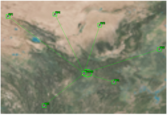
Figure 1.
The simulated aircraft and six LEO satellites for positioning.
In the process of navigation, the flight speed of the aircraft is taken as a known quantity, and the position of the aircraft in the simulation software is taken as the real position for a comparison with the navigation result. All simulated data were output once per second.
Figure 2 shows the change in GDOP values for the six satellites using Doppler positioning throughout the flight of the aircraft. DOPs are usually close to 1, which corresponds to the positioning equation of the pseudorange positioning. However, Doppler positioning was used in this article. The positioning equation of Doppler is different from that of pseudorange positioning, so the solution of the DOP value is also different. Obviously, the DOP value of Doppler positioning is greater than that of pseudorange positioning, but what we use for positioning are unknown LEO signals. For signals that we know little about, it is easier to acquire Doppler than to acquire a pseudorange or carrier phase, so we chose Doppler positioning. In the second half of the simulation, DOP mainly showed a rapid rise because only six LEO satellites were used in the simulation. Due to the highly dynamic characteristics of LEO satellites, the configuration of satellites changed rapidly, worsening DOP. Therefore, to use LEO satellite navigation, we need to frequently replace the used satellites to ensure a better DOP value.
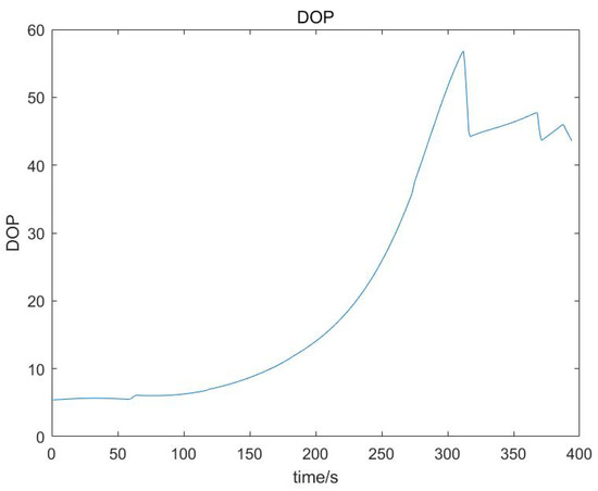
Figure 2.
GDOP for six Starlink satellites.
4.1.2. Initialization
In Section 2.2, two methods were proposed for finding the location of moving targets. To use the initialization method for the location of a moving target, an initialization process for the aircraft must be added. In this simulation, the aircraft was stationary for 60 s for initialization before it started moving, and the satellite orbital position and velocity, and satellite signal Doppler data were simulated for this minute using the software. All simulated data were output once per second.
The initialization process allows for solving the initial position of the aircraft, Doppler frequency drift rate , and frequency bias due to clock errors for each satellite.
4.2. Effect of Error Sources
The main error sources that affect the positioning using LEO SV Doppler shift measurements are the satellite position and velocity errors, and satellite clock drift. In this section, we use the control variable method to study the influence of various errors on positioning accuracy. The initialization time in Method 1 was 60 s, and the window length in Method 2 was N = 10.
4.2.1. Satellite Doppler Shift
The Doppler frequency of the satellite signal received by the receiver has a certain error compared with the theoretical value that is mainly caused by the clock difference. The deviation between the measured and theoretical values is modeled as follows:
Three different sets of Doppler drift and Doppler offset were randomly generated as shown in Table 1 and Table 2. Three different sets of Doppler errors were calculated from the data in the table, and the initial values of the three sets of Doppler errors were around 300, 150, and 20 Hz. The three sets of data were solved using the two positioning methods, and the results are shown in Figure 3. The leftmost circle means that no Doppler shift error had been added, that is, the Doppler shift error was 0.

Table 1.
Several different sets of satellite Doppler drift ()/ Hz/s.

Table 2.
Several different sets of Doppler offset ()/Hz.
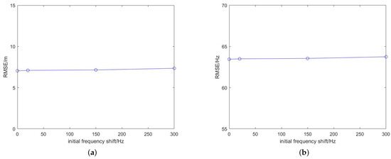
Figure 3.
RMSE of the Doppler positioning results of the two methods with several different sets of initial Doppler shift errors. (a) Initialization; (b) sliding window.
According to the results in Figure 3 and the positioning results under ideal conditions, error term added to the positioning equation modeling had the same form as that of Doppler frequency error , which could effectively eliminate the influence of the Doppler frequency error on the results.
4.2.2. Satellite Position Error
The error of the satellite position, predicted on the basis of TLE data and the SGP4 model, could be as high as 3 km. Most errors are concentrated in the tangential direction. The error model can be approximated as a quadratic model, and the coefficient of the quadratic term is small.
where is the standard deviation of the 3D orbit prediction error in meters, k is the discrete time step, s is the simulation data output time interval. , , and denote the initial position error, the primary term coefficient of error growth, and the quadratic term coefficient, respectively.
In the simulation, the satellite orbit predicted by TLE and SGP was regarded as the real orbit. However, in reality, there are errors in the satellite orbits predicted using TLE. Therefore, we wanted to simulate the effect of realistic positioning using TLE predicted orbits by adding errors to the perceived TLE predicted orbits. The initial errors of TLE orbit prediction could reach the order of hundreds of metres and gradually increase to the order of kilometers over time. We randomly generated three sets of initial position deviations of around 200, 1500, and 3000 m as the optimal, intermediate, and worst estimates of the initial position deviation, respectively, and the values of are shown in Table 3. The values of and were set to 1.16 m/s and 0.01 m/s for all satellites. Due to the short flight time of the simulated aircraft, the effect of on the orbit error was relatively small.

Table 3.
Several different sets of initial satellite orbit errors ()/m.
Three groups of satellite orbit data with different errors were used for target positioning, and the resulting positioning errors are shown in Figure 4. The leftmost circle means that no orbital position error had been added, that is, the orbital error was 0.
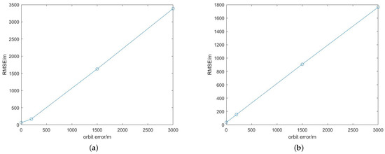
Figure 4.
The RMSE of the Doppler positioning results of the two methods under several different sets of orbital initial errors. (a) Initialization; (b) sliding window.
Figure 4 shows that the localization error of the moving target was approximately linear with the orbit error, and the localization error grew with the the orbit error. Comparing the localization errors of the two localization methods in Figure 4 shows that the sliding-window method could weaken the influence of the orbit error to a certain extent, and had higher localization accuracy than that of the initialization method.
The satellite orbit error greatly impacted the accuracy of the moving target positioning. The current methods of acquiring LEO satellite orbits are mostly TLE files and SGP4 models. If some methods can be found to correct the predicted orbit error or use other methods to obtain highly accurate satellite orbits, the positioning accuracy can be greatly improved.
4.2.3. Satellite Velocity Error
As with the satellite position, satellite velocity was also predicted using the TLE file and the SGP4 model, and had the same error growth trend. Three sets of initial velocity deviations were randomly generated at around 0.2, 1.5, and 3 m/s, as shown in Table 4, and the three sets of satellite orbital velocities with different errors were used to locate the moving target. The obtained positioning errors are shown in Figure 5. The leftmost circle means that no orbital velocity error had been added, that is, the orbital velocity error was 0.

Table 4.
Several different sets of satellite velocity initial errors (m/s).
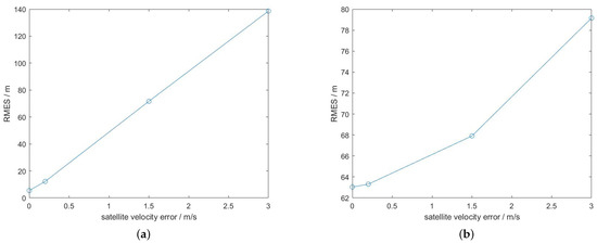
Figure 5.
The RMSE of the Doppler positioning results of the two methods under several different sets of velocity initial errors. (a) Initialization; (b) sliding window.
As shown in Figure 5, the location error of the moving target grew with the growth of the orbital velocity error. Comparing the location errors of the two location methods in Figure 5 shows that the sliding-window method could weaken the effect of the orbital velocity error to a certain extent, and had higher localization accuracy compared with that of the initialization method.
Same as the orbital position error, if some method can be found to achieve a highly accurate satellite orbital velocity level, the positioning accuracy can be improved greatly.
4.3. Total Error Effect
In Section 4.2, the method of the control variables was used to study the influence of different errors on positioning accuracy, but these errors exist simultaneously in the actual navigation process. Still using the simulation scenario in Section 4.1, we added several different sets of errors as shown in Table 5 to the simulation. The results can be seen in Figure 6.

Table 5.
Several different sets of errors.
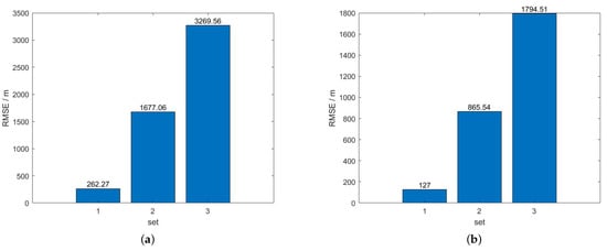
Figure 6.
The RMSE of the navigation results of the two methods under several different sets of errors. (a) Initialization; (b) sliding window.
5. Conclusions
In this paper, we studied the potential of using the Doppler shift of LEO satellite opportunity signals for dynamic target navigation, established the Doppler positioning equations for LEO satellite opportunity signals, and proposed two solution methods. We modeled the influence factors of the Doppler frequency shift of the LEO satellite opportunity signals, the errors of the satellite’s orbital position and velocity, and the Doppler shift due to satellite clock error, and evaluated the influence of the errors on the positioning accuracy by using a simulation. Simulation results show that the greatest factor affecting the positioning accuracy was the satellite orbit error, which was mainly due to the large error of the used predicted orbit itself. If a method can be found to reduce the orbit error, the positioning accuracy can be significantly improved.
Recently, many countries or companies around the world have been launching their own constellations of LEO satellites. The number of LEO satellites is foreseen to grow rapidly in the coming years. In the future, we hope to conduct motion target navigation experiments on the basis of the Doppler of LEO satellite opportunity signals, and further investigate the possibility of using the carrier-phase information of LEO satellite opportunity signals for dynamic target navigation.
Author Contributions
Conceptualization, C.Y., B.Z. and C.D.; methodology, C.Y., B.G. and L.Z.; validation, L.L. and H.J.; writing—original draft, C.Y.; writing—review and editing, Z.Z. and L.D. All authors have read and agreed to the published version of the manuscript.
Funding
This research was funded by the National Natural Science Foundation of China, grant numbers 61973314 and 41904014, and the Key Research and Development Program of Shaanxi, program number 2023-YBGY-223.
Data Availability Statement
Not applicable.
Conflicts of Interest
The authors declare no conflict of interest.
References
- Racelis, D.; Pervan, B.; Joerger, M. Fault-Free Integrity Analysis of Mega-Constellation-Augmented GNSS. 2019, pp. 465–485. Available online: https://www.aoe.vt.edu/content/dam/aoe_vt_edu/people/faculty/joerger/publications/ION%20GNSS+%202019%20paper%20Final.pdf (accessed on 15 January 2023).
- Reid, T.; Walter, T.; Enge, P.; Lawrence, D.; Cobb, H.; Gutt, G.; O’Conner, M.; Whelan, D. Navigation from low earth orbit—Part 1: Concept, current capability, and future promise In Position, Navigation, and Timing Technologies in the 21st Century; Morton, J., van Diggelen, F., Spilker, J., Jr., Parkinson, B., Eds.; Wiley: Hoboken, NJ, USA, 2021; Volume 2, pp. 1360–1380. [Google Scholar]
- Lawrence, D.; Cobb, H.S.; Gutt, G.; O’Connor, M.; Reid, G.R.; Walter, T.; Whelan, D. Innovation: Navigation from LEO; GPS World: Cleveland, OH, USA, 2017. [Google Scholar]
- Benzerrouk, H. Iridium Next LEO Satellites as an Alternative PNT in GNSS Denied Environments. Inside GNSS, 17 June 2019. [Google Scholar]
- Langley, R.B. Navigation from LEO: Current Capability and Future Promise; GPS World: Cleveland, OH, USA, 2017. [Google Scholar]
- Tan, Z.; Qin, H.; Cong, L.; Zhao, C. New Method for Positioning Using IRIDIUM Satellite Signals of Opportunity. IEEE Access 2019, 7, 83412–83423. [Google Scholar] [CrossRef]
- Tan, Z.; Qin, H.; Cong, L.; Zhao, C. Positioning Using IRIDIUM Satellite Signals of Opportunity in Weak Signal Environment. Electronics 2020, 9, 37. [Google Scholar] [CrossRef]
- Neinavaie, M.; Khalife, J.; Kassas, Z.M. Blind Doppler Tracking and Beacon Detection for Opportunistic Navigation with LEO Satellite Signals. In Proceedings of the 2021 IEEE Aerospace Conference (50100), Big Sky, MT, USA, 6–13 March 2021; pp. 1–8. [Google Scholar]
- Khalife, J.; Neinavaie, M.; Kassas, Z.M. Blind Doppler Tracking from OFDM Signals Transmitted by Broadband LEO Satellites. In Proceedings of the 2021 IEEE 93rd Vehicular Technology Conference (VTC2021-Spring), Helsinki, Finland, 25–28 April 2021; pp. 1–5. [Google Scholar]
- Khalife, J.; Neinavaie, M.; Kassas, Z.M. The First Carrier Phase Tracking and Positioning Results With Starlink LEO Satellite Signals. IEEE Trans. Aerosp. Electron. Syst. 2022, 58, 1487–1491. [Google Scholar] [CrossRef]
- Neinavaie, M.; Khalife, J.; Kassas, Z.M. Exploiting Starlink signals for navigation: First results. The Institute of Navigation. In Proceedings of the 34th International Technical Meeting of the Satellite Division of the Institute of Navigation, St. Louis, MO, USA, 20–24 September 2021. [Google Scholar]
- Neinavaie, M.; Khalife, J.; Kassas, Z.M. Acquisition, Doppler Tracking, and Positioning With Starlink LEO Satellites: First Results. IEEE Trans. Aerosp. Electron. Syst. 2022, 58, 2606–2610. [Google Scholar] [CrossRef]
- Xie, X.; Geng, T.; Zhao, Q.; Liu, X.; Zhang, Q.; Liu, J. Design and validation of broadcast ephemeris for low earth satelites. GPS Solut. 2018, 22, 54. [Google Scholar] [CrossRef]
- Shmaliy, Y.S. Linear unbiased prediction of clock errors. IEEE Trans. Ultrason. Ferroelectr. Freq. Control. 2009, 56, 2027–2029. [Google Scholar] [CrossRef] [PubMed]
- Jing, S.; Hu, S.; Ping, J. Accuracy Analysis of TLE and SGP4 Orbit Calculation for Low Orbit Space Targets. In Proceedings of the Forum on Frontier Technologies in Surveying and Mapping Science Bulletin of Surveying and Mapping, Nanjing, China, 18–19 October 2008. (In Chinese). [Google Scholar]
- Morales, J.J.; Khalife, J.; Cruz, U.S.; Kassas, Z.M. Orbit Modeling for Simultaneous Tracking and Navigation using LEO Satellite Signals. In Proceedings of the 32nd International Technical Meeting of the Satellite Division of the Institute of Navigation, Miami, FL, USA, 16–20 September 2019. [Google Scholar]
- Jardak, N.; Jault, Q. The Potential of LEO Satellite-Based Opportunistic Navigation for High Dynamic Applications. Sensors 2022, 22, 2541. [Google Scholar] [CrossRef] [PubMed]
- Aksnes, K.; Andersen, P.H.; Haugen, E. A precise multipass method for sattlite doppler positioning. Celest. Mech. 1988, 44, 317–338. [Google Scholar] [CrossRef]
- Chan, Y.T.; Towers, J.J. Passive localization from Doppler shifted frequency measurements. In Proceedings of the ICASSP 91: 1991 International Conference on Acoustics, Speech, and Signal Processing, Toronto, ON, Canada, 14–17 April 1991; Volume 40, pp. 1465–1468. [Google Scholar]
- Hsu, W.-H.; Jan, S.-S. Assessment of using Doppler shift of LEO satellites to aid GPS positioning. In Proceedings of the 2014 IEEE/ION Position, Location and Navigation Symposium—PLANS 2014, Monterey, CA, USA, 5–8 May 2014; pp. 1155–1161. [Google Scholar] [CrossRef]
- Othieno, N.; Gleason, S. Combined Doppler and time free positioning technique for low dynamics receivers. In Proceedings of the 2012 IEEE/ION Position, Location and Navigation Symposium, Myrtle Beach, SC, USA, 23–26 April 2012; pp. 60–65. [Google Scholar] [CrossRef]
- Analytical Graphics, Inc. Satellite Tool Kit Uesr’s Manual; Analytical Graphics, Inc.: Exton, PA, USA, 2002. [Google Scholar]
Disclaimer/Publisher’s Note: The statements, opinions and data contained in all publications are solely those of the individual author(s) and contributor(s) and not of MDPI and/or the editor(s). MDPI and/or the editor(s) disclaim responsibility for any injury to people or property resulting from any ideas, methods, instructions or products referred to in the content. |
© 2023 by the authors. Licensee MDPI, Basel, Switzerland. This article is an open access article distributed under the terms and conditions of the Creative Commons Attribution (CC BY) license (https://creativecommons.org/licenses/by/4.0/).