Abstract
To enable mobile robots to effectively deal with the emergency of visual contamination, contingency planning based on case-based reasoning (CBR) was performed in this paper. First, for a wheeled mobile robot (WMR) equipped with a chameleon-inspired visual system, a target search model in chameleon-inspired binocular negative correlation movement (CIBNCM) mode was established. Second, a CBR-based contingency planning model of visual contamination for WMRs was established, where the reasoning process using CBR for visual contamination was analyzed in detail. Third, through the analysis of environment perception when visual contamination occurs, a perception model in chameleon-inspired visual contamination for WMRs was built. Finally, to validate the proposed approach, a contingency planning experiment scheme for visual contamination was designed based on the robot’s general planning of target tracking, and the experimental result is discussed. The proposed CBR-based contingency planning approach for visual contamination can reason out effective solutions corresponding to the contamination situations. The rationality of the approach was verified by experiments with satisfactory results. Moreover, compared with the contingency planning method based on rule-based reasoning, the accuracy of target retracking after the robot visual system is contaminated is significantly higher for the CBR-based contingent planning method used in this paper.
1. Introduction
Visual sensors are an extremely important tool for robot environmental perception, with the characteristics of rich sensory information, etc. It is an essential requirement of mobile robots equipped with visual systems for many practical application fields, ranging from space exploration to engineering rescue [1]. Figure 1a shows the “X-RHex” six-legged robot [2] working in a muddy environment, Figure 1b shows the “Red Snake” [3,4] snake-like robot climbing in the pipeline, and the Hull BUG wheeled robot shown in Figure 1c was developed by the U.S. navy, which is mainly used for Hull cleaning [5]. Due to the complex and unknown working environments of these mobile robots, their visual systems are vulnerable to contamination, lowering the quality of images and affecting regular work. Once this emergency occurs, it is difficult for humans to clean it, and the general way is to terminate the task and command the robot to return. Moreover, the return task is also difficult to complete due to the contaminated visual system. Consequently, it is important to address unexpected events through contingency planning for the robot’s visual contamination.
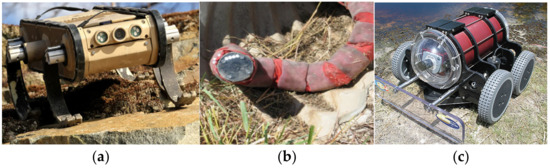
Figure 1.
Visual contamination of mobile robots: (a) X-RHex [2]; (b) Red Snake [3,4]; (c) Hull BUG [5].
Currently, the measures for visual contamination mainly depend on manual cleaning, automated cleaning systems, and contaminated image processing algorithms. The manual cleaning approach requires the robot to return to the workstation or stop and wait. This can result in wasted energy, and cleaning itself will interfere with the normal use of the equipment. It is not suitable for mobile robots. Automatic cleaning systems are often used in smart cars. An automatic cleaning mechanism is designed on the outside of the camera to restore the normal function of the sensor system. Most studies use supervised sensors to collect data to determine whether the camera has been contaminated [6]. Once the sensor is found to be contaminated, a cleaning mechanism such as a water spray pipe or blower is immediately used to clean the camera [7,8] and a heater is used to dry the remaining water droplets on the camera [9]. In addition, there is visual contamination caused by blood, debris, and other factors in medical testing. Automatic cleaning systems are common in the field of medical robots such as laparoscopic photography [10,11,12]. There are currently many cleaning methods that use the principle of ultrasound [13]. By developing specialized chips and glass [14,15], microvibration is used to quickly detect and remove dirt, ice, and water. The main focus of contaminated image processing algorithms is in the areas of image fog removal and image rain removal. In 2010, He [16] proposed a dark channel prior method for image defogging, which can effectively remove fog from images. In 2012, L.W. Kang [17] first proposed the issue of image rain removal at the IEEE conference, which led to the development of these two image processing algorithms. With the continuous development of deep learning [18,19], it has become increasingly widely used in the field of automation [20,21], and image processing-related tasks have also begun to apply deep learning technology. By utilizing machine learning [22,23] and generative adversarial networks [24,25], traditional dark channel prior methods have been improved to achieve end-to-end image defogging. The research on rain removal algorithms focuses more on improving various neural networks [26,27,28,29], ultimately achieving effective end-to-end image rain removal. In summary, the automatic cleaning system can quickly clean the camera after detecting pollution but requires a real-time control system and precise mechanical structure design. Similarly, current pollution image processing algorithms mainly focus on fog and rain, while robots face complex pollutants when working outdoors, and rely solely on image restoration cannot solve the pollution problem. The application of these two methods in the field of outdoor mobile robots with complex environments still needs improvement.
Intelligent decision control is the development trend of automation systems [30,31,32] and solving visual contamination can be transformed into decision-planning problems. Continuity planning refers to monitoring the status of autonomous robots during operation. When an unexpected event is detected, the robot autonomously generates a set of targeted response strategies based on the current emergency, maintaining the ability to continuously move with degraded functionality. NASA has conducted extensive research on emergency planning for Mars rovers. Dearden [33] proposed an incremental emergency planning method to address the needs of Mars rovers for time and resource continuity. A seed plan was constructed and emergency branches were gradually added. NASA has also conducted research on personnel decision-making and scheduling issues after emergencies and unexpected events such as suborbital re-entry of Mars probes [34,35]. In the field of intelligent vehicles, Salvado [36] proposed an emergency maneuver planner for the failure of other decision processes. This planner can use heuristic best-first search algorithms to reorganize discrete motion primitives for different scenarios, resulting in vehicle behavior that is suitable for the current situation. In robotics, Shah [37] proposed a lattice-based 5D trajectory planner. This planner can estimate collision risk and infer emergency maneuvering behavior and can integrate the collision prevention behavior of unmanned boats into the search for dynamic feasible paths. The emergency path planner proposed by Hardy [38] can generate multiple paths simultaneously to cope with dynamic obstacles. Underwater robots have high costs and a high risk of loss. Currently, they only perform conservative and simple operations and cannot fully realize their potential. Harris [39] suggested that robot uncertainty could be modeled to observe the progress of their work and the surrounding environment. If a low battery level is observed, another data collection task is scheduled, and if the battery level is sufficient, the primary task is performed.
Visual contamination occurs with the characteristics of dynamics, uncertainty, etc. In the process of robot environmental perception, conventional planning cannot properly address these problems [40,41]. In terms of contingency planning for visual contamination, robots need to automatically determine whether contamination occurs and self-learn to deduce coping strategies that are highly adaptive to the current situation [42]. Case-based reasoning (CBR) can meet the above requirements well.
CBR is used to solve new problems by searching for similar historical cases and using the existing experience or results [43,44]. It is a knowledge-based problem-solving method in the field of artificial intelligence (AI) that originated in Roger Schank’s description in Dynamic Memory. This method derives from humans’ cognitive mental activities, alleviating the bottleneck of knowledge acquisition in conventional knowledge systems. It combines quantitative analysis with qualitative analysis and has the characteristics of a dynamic knowledge base and incremental learning [45]. In this way, not only can it liberate human thought from conventional thinking, but it can also generate relatively thorough strategies by considering varieties of similar cases, making up for limited human thought. The basic steps of CBR can be summarized as case representation, case retrieval, case reuse, case revision, and case retention, known as 5R [46].
Consequently, CBR-based contingency planning was employed for the visual contamination of mobile robots in this paper to enable the robot to cope with this emergency. First, for a WMR equipped with the chameleon-inspired visual system, a target search model in CIBNCM mode was established. Second, a CBR-based contingency planning model for the visual contamination of mobile robots was established, and the process of using CBR theory for the contingency planning of visual contamination was analyzed in detail. Third, an environmental perception model with visual contamination for mobile robots was built to analyze how the robot perceives the environment with visual contamination, including the visual contamination state space and the corresponding action space. Finally, experiments were implemented to verify the effectiveness of the proposed CBR-based contingency planning strategy for visual contamination of WMRs.
2. Description of the Chameleon-Inspired Visual System for WMRs
The chameleon is called “the lion crawling on the ground” because its visual system plays an important role in defense and hunting. Its two eyes can achieve independent movement, and they are not coordinated. This kind of phenomenon is very rare in animals, as shown in Figure 2. Ott, Avni, et al. named the global scanning strategy of chameleons searching for prey in environments “negative correlation” scanning rules [47,48,49,50].
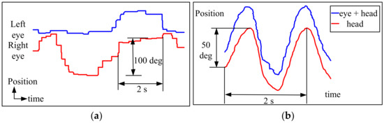
Figure 2.
Movement mechanism of the chameleon visual system [47]: (a) Horizontal components of binocular eye position during eye search movements in a chameleon; (b) Horizontal components of the position of one eye and head during the pursuit of sinusoidal prey movements.
In this paper, based on the analysis of the movement mechanism of chameleon visual systems, as well as the similarity between the visual systems of WMRs and chameleons, a chameleon-inspired visual system equipped on a wheeled mobile robot was established, as shown in Figure 3a. The visual system consisted of two cameras (avenir-SSL06036M made by Seiko Japan) and two CMOS image sensors (Suntime-200 made by Sun Time Taiwan), as well as five servos to control the PTZ rotation in 5DOFs, including the horizontal rotation of the neck, the horizontal rotation, and the pitch of two cameras.
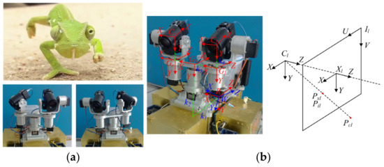
Figure 3.
The chameleon-inspired visual system of mobile robots: (a) chameleon-inspired rotation of eyes in negative correlation + neck; (b) coordinate system of the visual system.
Based on the built visual system, the coordinate systems were established as shown in Figure 3b. All the coordinate systems accorded with the right-hand rule, and the corresponding parameters are shown in Table 1.

Table 1.
Parameters of the coordinate systems.
According to the imaging coordinate system, assuming that the cameras are distortion-free, the intrinsic parameter model of the camera is as follows:
where is the target coordinate in the image coordinate system; is the coordinate in the image coordinate system where the optical axis passes through the imaging plane; is the target coordinate in the camera coordinate system; and are the amplification coefficients in the directions.
The external parameter model can be described as follows:
where is the coordinate of the object in the world coordinate system; is the rigid body transformation from the robot-body coordinate system to the world coordinate system; and is the rigid body transformation from the camera coordinate system to the robot-body coordinate system.
3. Target Search Model in CIBNCM Mode for WMRs
Based on the movement mechanism of the chameleon visual system, a target search model in chameleon-inspired binocular negative correlation movement (CIBNCM) mode for WMRs was established, as shown in Equation (5). With this model, the negative correlation movement behavior of two cameras in the process of target search was analyzed, and the coordinated behavior of the eyes and neck was discussed. The relationship between the rotation angles of the cameras and neck and the camera’s field of view (FOV), the robot’s region of interest (ROI), and the overlap angle is quantitatively described. To deploy the contrastive analysis, a target search model in binocular coordinated movement (BCM) mode was also built, as shown in Equation (6).
where
- —describes the target search model in CIBNCM and BCM mode for WMRs and is represented by , respectively;
- —expresses the focal length of cameras;
- —is the obtained FOV in CIBNCM and BCM mode;
- —denotes the detected target characteristic using the selective attention algorithm.
The relationship between the rotation angles of the two cameras and neck and the camera’s FOV, the robot’s ROI, and the overlap angle is shown in Equation (7):
where
- —represents the robot’s ROI;
- —is the horizontal and vertical FOV of each camera, ;
- —denotes the overlap angle, ;
- —is the rotation time of cameras in the horizontal and vertical direction in CIBNCM and BCM mode, .
According to the FOV of each camera, the robot’s ROI, and the overlap angle, the rotation times of cameras in the horizontal and vertical directions can be deduced, as follows:
Subsequently, to scan the horizontal ROI, the two cameras and neck need to rotate by the following angles.
where is the label of cameras, corresponding to .
Similarly, the rotation angles of cameras in the vertical direction are obtained as follows:
Through the above modeling analysis of the two search modes, a few points can be found under the condition of the same size of ROI. For the horizontal rotation angles of cameras, first, the rotation times in CIBNCM mode are reduced by half compared to those in BCM mode, which not only indicates that the power consumption of camera servos can be reduced by half, but also that the search efficiency can be doubled. Second, the processing image number of the CIBNCM mode is half that of the BCM mode, which can significantly reduce the burden of image processing and improve the processing efficiency. Finally, the introduction of the neck increases the freedom of the visual system and creates the same search area through three axis rotation, improving the search efficiency. Briefly, the combination of the neck and cameras makes the search more flexible, and the rotation angles of the cameras smaller. For the vertical rotation angles of cameras, under normal working conditions of the cameras, there is no difference between the two models; if visual contamination occurs, the CIBNCM mode can give full play to the advantage of its negative correlation movement, achieving complementary visual perception.
4. CBR-Based Contingency Planning of Chameleon-Inspired Visual Contamination for WMRs
A basic assumption of traditional robot artificial intelligence planning is that there is no uncertainty in the external environment in which the robot is located, i.e., the robot has all the a priori knowledge of the external environment and all the action outputs of the robot are predictable. Therefore, traditional robot planning is based on deterministic planning, which has disadvantages such as poor fault tolerance and the need for human monitoring at all times. Contingency planning in this paper was perception-based behavior planning for mobile robots in response to unexpected events. Given the randomness and diversity of contingencies, no deterministic prediction can be made, so a CBR-based state-behavior planning model was adopted, i.e., a responsive dynamic planning method that uses CBR to reason about the corresponding behavior strategy based on the current state of the robot. CBR is an incremental learning method that continuously updates and improves the case base to make the reasoning results more accurate to better adapt to the specific situation [51,52,53]. It is noted that the contingency planning of visual contamination for mobile robots is responsive planning, which is a planning method that generates action plans directly based on observations of the state of the world. Contingency planning is based on the general planning of robots and is triggered only when unexpected events occur. The CBR-based contingency planning model of chameleon-inspired visual contamination for WMRs was established, as shown in Equation (11):
where
- is the CBR-based contingency planning space of chameleon-inspired visual contamination for WMRs;
- represents the state space and corresponding action space of visual contamination for WMRs, respectively;
- denotes the CBR-based reasoning space, and expresses every step of the CBR-based reasoning process, respectively.
As shown in Figure 4, the visual system was monitored in the process of robots perceiving the environment. Once the contaminant was detected, the contamination detection algorithm was used to extract the required parameters of visual contamination cases. Then, the characteristic parameters were input into the CBR reasoning cycle to retrieve similar cases in the case base. Subsequently, the solutions of the retrieved base cases were reused to obtain a plan corresponding to the current contamination condition, and it was output to the robot control system, generating a series of actions. Finally, the visual contamination plan was evaluated, cases were stored selectively, and the case base was maintained to guarantee real-time.
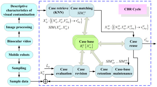
Figure 4.
CBR-based contingency planning of chameleon-inspired visual contamination for WMRs.
4.1. Case Representation of Visual Contamination
Case representation is composed of case description characteristics and solution characteristics. The binocular visual contamination of WMRs is characterized by the transparency of the FOV, the centroid position of contamination, and the camera contamination topology, expressed as . The solution characteristic is the coping strategy of visual contamination, expressed as . Therefore, the case representation of visual contamination for WMRs can be described as Equation (12).
where is the case, is the number of cases in the case base, are the name and time of the case, is the value of the description characteristics of the case, and is the value of the solution characteristic of the case.
Then, based on the case representation, the case base of the visual contamination for WMRs is established, as shown in Equation (13),
The key to case retrieval is to objectively define and quantify the similarity between cases. K-Nearest Neighbors (KNN) is the most widely used case similarity calculation method, which is easy to understand and realize. It is known as weight retrieval because the case similarity is determined by the weighted summation of every characteristic.
It is known that the base case is expressed as and the target case is described as , where . Therefore, the characteristic similarity and case similarity can be calculated by Equations (14) and (15), respectively.
where is the weight of every characteristic. and meets the symmetry and reflexivity. The higher is, the higher the similarity between the target case and the base case. Finally, all the matching base cases can be retrieved and ranked in descending order of similarity and time .
4.2. Case Reuse of Visual Contamination
In general, the retrieved base cases are not perfectly matched with the target case. Therefore, the solution of the retrieved base cases cannot be directly used for the target case, and it needs to be modified and reused. It is assumed that the matching base cases are described as , where is the number of matching base cases. The solution of the target case can be obtained by Equation (16) and it can be found that the solution weight of the matching cases in the target case is proportional to the similarity between the matching cases and the target case.
4.3. Case Evaluation and Revision of Visual Contamination
Through the above case retrieval and reuse, we can obtain the solution to the target case. However, what is the accuracy of the solution? We need to evaluate the implementation of the solution. If successful, this new case will be selectively saved in the case base according to the following rules; otherwise, the solution needs to be revised. The pseudo-code for case evaluation and revision is shown in Figure 5.
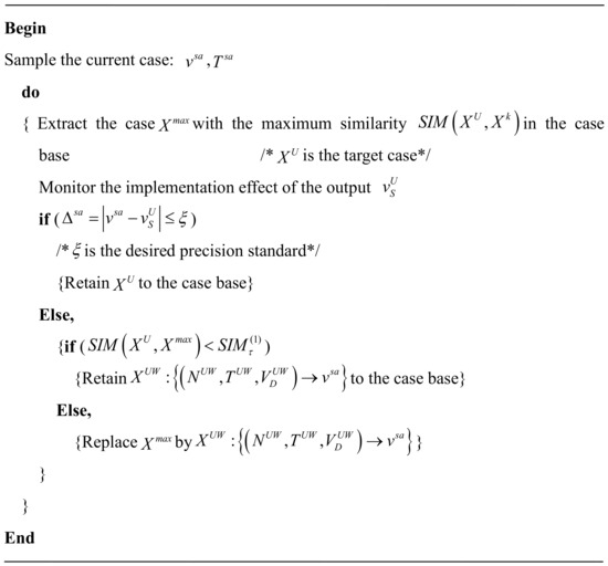
Figure 5.
Pseudo-code for case evaluation and revision.
4.4. Case Retention and Case-Base Maintenance of Visual Contamination
CBR is a kind of experience-based reasoning method, and the diversity and advancement of experience play an important role in the accuracy of reasoning results. As time goes on, the number of cases is increasing; however, the continuous increase will not only lead to the overlap of cases and loss of representation but will also affect the efficiency and accuracy of case reasoning. In addition, with the development of social sciences, cases that are too old may no longer adapt to the current situation. Therefore, to increase the diversity of the case base and maintain the real-time of cases, we need to properly handle the retention and maintenance of cases. In this paper, the human supervision-based method was used to achieve the retention and maintenance of cases. The pseudo-code for case retention and case base maintenance based on human supervision is shown in Figure 6.
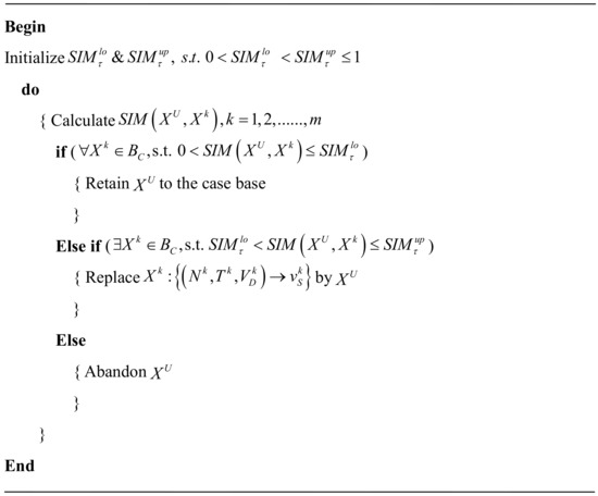
Figure 6.
Pseudo-code for case retention and case base maintenance based on human supervision.
5. Perception Model in Chameleon-Inspired Visual Contamination of WMRs
In terms of the contamination of the chameleon-inspired visual system, an environmental perception model was established, as shown in Figure 7. First, through the analysis of the contamination condition of the binocular visual system, the state space was established based on the characteristics of visual contamination. Second, coping strategies were designed according to the contamination condition of the binocular visual system and, further, the action space of visual contamination was established corresponding to the state space.
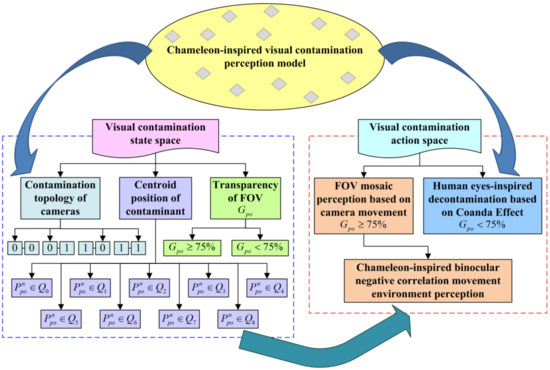
Figure 7.
Perception model in chameleon-inspired visual contamination for WMRs.
According to different visual contamination situations described by the description characteristics, the coping scheme of visual contamination was designed. First, when the transparency of the FOV was greater than or equal to 75%, FOV mosaic perception based on camera movement was used to perceive the ROI. It can preserve the degraded visual perception and avoid stopping normal work to clean the contamination. In contrast, when the transparency of the FOV was less than 75%, the robot was seriously contaminated and had to be cleaned immediately. Human eye-inspired decontamination based on the Coanda effect was adopted, which is not described in this paper. Second, the location of the visual contamination was divided into nine typical positions based on the coordinate quadrant. Finally, the camera contamination topology of the binocular visual system was divided into four kinds of arrangements (00, 01, 10, 11).
In this paper, camera transparency was defined as the ratio of the camera non-contamination area to the entire camera area, so the equations for calculating the transparency of a single camera and the binocular visual system were obtained as follows:
where denotes the contamination area of the monocular camera, is the area of the entire camera, and represents the contamination area of the left and right cameras, respectively.
To determine the centroid position of the contamination, define the distance similarity as . That is, the similarity is expressed by the distance between the centroid of contamination and the nine reference points. The smaller the distance is, the higher the similarity between the two points.
where denotes the coordinates of the contamination centroid, are the coordinates of the reference points, and .
Therefore, the perception model in chameleon-inspired visual contamination for WMRs can be established as follows:
where
- is the perception space in chameleon-inspired visual contamination for WMRs, consisting of the state space and action space of visual contamination;
- is the state space of chameleon-inspired visual contamination, where represents the transparency of the FOV, the centroid position of contamination, and the camera contamination topology, respectively,—is the action space of chameleon-inspired visual contamination, where describes the robot’s coping strategies when the transparency of the FOV satisfies , and is the robot’s coping strategies when the transparency of the FOV satisfies .
When , the robot’s coping strategy is FOV mosaic perception based on camera movement. The effective horizontal and vertical FOV of each camera after contamination is defined as , so the effective FOV of the binocular visual system can be determined by Equation (20),
The search model in CIBNCM mode was used to perceive the environment after contamination in this paper. According to the effective FOV of each camera after contamination, the robot’s ROI, the overlap angle, and the rotation times of cameras in the horizontal and vertical directions can be deduced as follows:
Subsequently, to scan the horizontal ROI, the two cameras and neck need to rotate by the following angles.
Similarly, the rotation angles of cameras in the vertical direction are
Finally, in terms of the different contamination situations described by the transparency of the FOV, the centroid position of contamination, and the camera contamination topology, the corresponding coping strategies of WMRs can be obtained as follows:
6. Experiments and Comparison
To validate the proposed CBR-contingency planning method for visual contamination, an environment perception experiment in chameleon-inspired visual contamination was designed for WMRs, as shown in Figure 8. It is noted that the contingency planning of visual contamination was based on the general planning of robot target tracking. Target tracking is the basic task of the robot, and contingency planning is triggered only when visual contamination is detected.
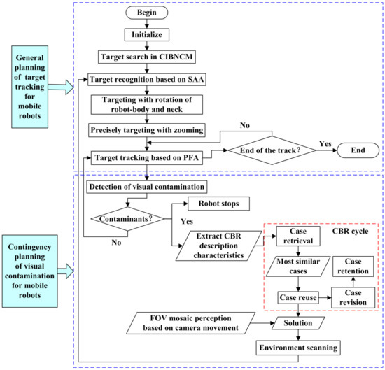
Figure 8.
CBR-based process of environment perception in chameleon-inspired visual contamination for WMRs.
First, the target search model in CIBNCM mode was adopted for mobile robots to scan the environment and the target was extracted using the selective attention algorithm (SAA). Second, to achieve high accuracy, rotation of the robot body and neck and a zooming model were used to realize targets. Finally, real-time target tracking was achieved using a particle filter algorithm (PFA). In the process of target tracking, real-time detection of visual contamination was carried out. Once contaminants were found, the robot was commanded to stop. Meanwhile, the description characteristics of visual contamination were extracted and input to the CBR cycle to reason out solutions using the FOV mosaic perception based on camera movement. Then, the obtained solution was output to the robot control system to track the target again.
In this experiment, the robot was located on flat ground to search and track the red object in front, as shown in Figure 9. Contaminants were monitored in the process of target tracking. At the 44th second, contaminants were detected and the robot stops. The corresponding description characteristics were . Inputting them into the CBR cycle, the reasoned-out coping strategy based on FOV mosaic perception is as follows:
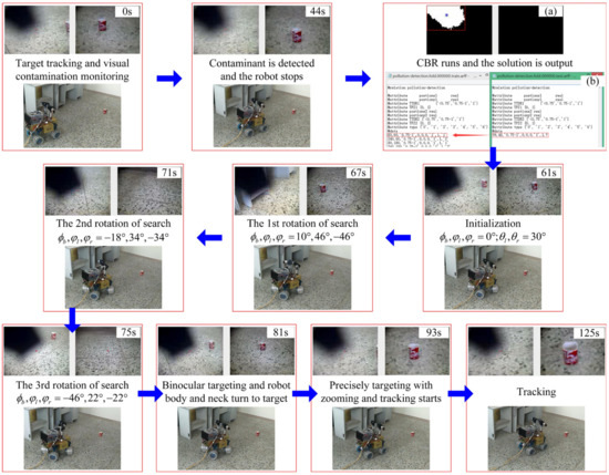
Figure 9.
Target tracking process of WMRs with visual contamination using CBR for contingency planning.
Subsequently, the robot visual system performed the above CBR reasoning solution and took pictures once when each rotation stops. Through the analysis of the obtained six images, it was determined that, when the neck and right camera rotate by , the area at has the highest saliency. Then, the orientation of the object was calculated with . Through the rotation and zooming model, the robot can aim at the target precisely.
Finally, the target was tracked again and the tracking error curve is shown in Figure 10. The tracking error was between plus or minus 15 pixels, which shows that the tracking effect is satisfactory.
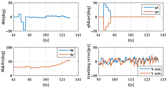
Figure 10.
Tracking data curve of WMRs with visual contamination using CBR for contingency planning.
The experimental results show the following: on the one hand, the contingency planning experiment scheme for visual contamination based on the robot’s general planning of target tracking is reasonable; on the other hand, the proposed CBR-based contingency planning method for visual contamination is validated, which can reason out proper solutions for the current contamination situation.
In addition, to further verify the effectiveness of the method, a comparison experiment of the RBR-based contingency planning method was designed. By comparing and analyzing the accuracy of robot target retracking after contingency planning of visual contamination based on the two reasoning methods, the coping ability of the contingency planning methods based on two reasoning methods for the visual contamination problem was compared and analyzed.
Knowledge reasoning is the thinking process of reasoning new knowledge from existing knowledge according to a certain strategy through a computer system [54,55]. That is, after inputting the problem to be solved, the existing design cases, expert experience, computational formulas, design specifications, and other knowledge in the knowledge base are called to simulate human thinking to solve the problem. Common knowledge reasoning methods are case-based reasoning (CBR) and rule-based reasoning (RBR). RBR uses a rule base and inference engine for reasoning, which relies more on the organization and form of rules and requires higher abstraction and induction ability for problem solution [56,57]. Based on rule-based reasoning, rule-based knowledge, such as expert experience, computational formulas, and design specifications, is abstracted into symbolic and normative concrete generative rules, and the rules are matched with facts to obtain conclusions through rule-based reasoning. The process of RBR-based contingency planning for robot vision contamination in this paper is shown in Figure 11.
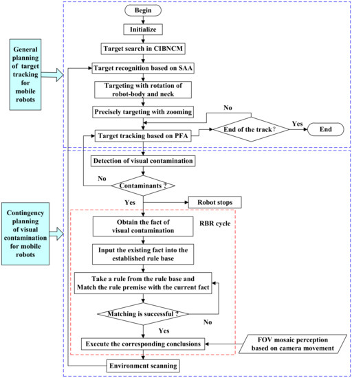
Figure 11.
RBR-based contingency planning process of visual contamination for WMRs.
In the process of target tracking, the robot performs image processing on the image information obtained from binocular vision, thus realizing real-time detection of visual contamination. Once the contaminant is found, the robot is ordered to stop moving and the fact of the visual contamination is extracted and input into the rule base. The rule premise is matched with the current fact until the matching is successful, and the rule conclusion, i.e., the solution, is obtained and output to the robot control system to execute it for target retargeting and tracking. For the same contamination case as the CBR-based contingency planning experiment, the fact of its visual contamination is described as and the solution inferred by RBR is
The results of the RBR-based contingency planning experiment are shown in Figure 12, from which we can see that, for the same contamination situation as the CBR-based contingency planning experiment, the robot vision system cannot lock the target well due to the low accuracy of the RBR solution. The two cameras and the neck produce significant shaking during the target tracking process and the accuracy of the robot target tracking is reduced. The tracking error is basically between plus and minus 25 pixels and the tracking curve oscillates seriously. In comparison, in the CBR-based contingency planning experiment, the two cameras and the neck basically remain motionless during the target tracking process, the tracking error is basically between plus and minus 15 pixels, and the tracking accuracy is higher. Therefore, for the contingency planning of visual contamination in this paper, the CBR-based planning method has better adaptability and higher planning accuracy.
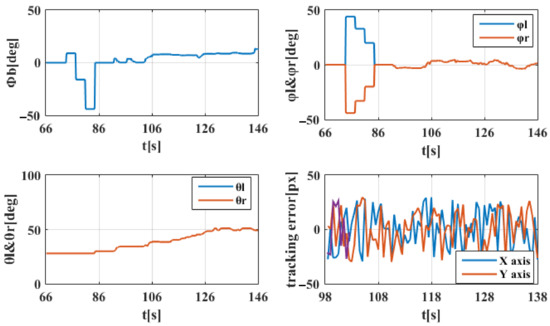
Figure 12.
Tracking data curve of WMRs with visual contamination using RBR for contingency planning.
7. Conclusions
In this paper, to improve the adaptability of autonomous mobile robots to unstructured environments, a CBR-based contingency planning method for robot visual contamination was proposed to address the problem that the visual system of a robot is highly susceptible to contamination during field operations, so that it has the ability to autonomously handle the contingency of visual contamination. First, the negative-correlation movement mechanism of the chameleon visual system was introduced to the visual system of mobile robots to improve the search efficiency of targets. Second, through the analysis of visual contamination in the process of robot environment perception, a CBR-based contingency planning model was proposed, where the CBR reasoning process was described in detail. Third, a perception model in chameleon-inspired visual contamination for WMRs was established, where the action space of environment perception was analyzed corresponding to different state spaces of visual contamination. Finally, a contingency planning experiment scheme for visual contamination was designed based on the robot’s general planning of target tracking, and the proposed approach was validated by the experimental results. The tracking error was between plus or minus 15 pixels, indicating a good tracking effect. This shows that the CBR-based contingency planning method of visual contamination proposed in this paper can reason out an effective solution based on the current contamination situation, which can enable the robot to effectively cope with the problem of visual contamination in the working process and ensure the continuous perception ability of the mobile robot to continue the general planning of target tracking. Moreover, by comparing with the RBR-based contingent planning method, it was found that the accuracy of target retracking after the robot visual system is contaminated is significantly higher for the CBR-based contingent planning method used in this paper.
In view of the complexity and dynamics of the environment in which the robot is located, the visual contamination of the robot also varies. Therefore, future research will focus on analyzing and detecting different visual contamination situations of the robot in complex environments and the corresponding CBR reasoning process. Through contingency planning for the emergency of a robot’s visual contamination, the robot is equipped with autonomous problem-solving abilities to achieve maximum adaptation to the working environment.
Author Contributions
Conceptualization, Y.X. and H.Y.; methodology, Y.X. and C.L.; software, H.Y. and Y.S.; validation, Y.X., H.Y. and C.L.; formal analysis, L.W and Y.S.; investigation, Y.S.; resources, Y.X. and C.L.; data curation, Y.X. and H.Y.; writing—original draft preparation, Y.X.; writing—review and editing, C.L., Y.S. and L.W.; visualization, H.Y.; supervision, C.L.; project administration, Y.X.; funding acquisition, Y.X and L.W. All authors have read and agreed to the published version of the manuscript.
Funding
This research was funded by the National Natural Science Foundation of China (52275264), the Scientific Research Foundation of Education Department of Liaoning Province (LJKQZ20222446), and the Doctoral Research Initiation Foundation of Shenyang Agricultural University (2017500065).
Institutional Review Board Statement
Not applicable.
Informed Consent Statement
Not applicable.
Data Availability Statement
Data sharing is not applicable to this article. No new data were created or analyzed in this study.
Acknowledgments
The authors would like to thank Xu He for his helpful comments and suggestions.
Conflicts of Interest
The authors declare no conflict of interest.
References
- Corke, P. Robotics, Vision and Control; Springer Tracts in Advanced Robotics; Springer International Publishing: Cham, Switzerland, 2017; Volume 118, ISBN 978-3-319-54412-0. [Google Scholar]
- Saranli, U.; Buehler, M.; Koditschek, D.E. RHex: A Simple and Highly Mobile Hexapod Robot. Int. J. Robot. Res. 2001, 20, 616–631. [Google Scholar] [CrossRef]
- Wright, C.; Johnson, A.; Peck, A.; McCord, Z.; Naaktgeboren, A.; Gianfortoni, P.; Gonzalez-Rivero, M.; Hatton, R.; Choset, H. Design of a Modular Snake Robot. In Proceedings of the 2007 IEEE/RSJ International Conference on Intelligent Robots and Systems, San Diego, CA, USA, 29 October 2007–2 November 2007; IEEE: Piscataway, NJ, USA, 2007; pp. 2609–2614. [Google Scholar]
- Wright, C.; Buchan, A.; Brown, B.; Geist, J.; Schwerin, M.; Rollinson, D.; Tesch, M.; Choset, H. Design and Architecture of the Unified Modular Snake Robot. In Proceedings of the 2012 IEEE International Conference on Robotics and Automation, Saint Paul, MN, USA, 14–18 May 2012; IEEE: Piscataway, NJ, USA, 2012; pp. 4347–4354. [Google Scholar]
- Souto, D.; Faina, A.; Lopez-Pena, F.; Duro, R.J. Lappa: A New Type of Robot for Underwater Non-Magnetic and Complex Hull Cleaning. In Proceedings of the 2013 IEEE International Conference on Robotics and Automation, Karlsruhe, Germany, 6–10 May 2013; IEEE: Piscataway, NJ, USA, 2013; pp. 3409–3414. [Google Scholar]
- Rice, W.M.; Wittenstein, N. Sequential Sensor Cleaning System for Autonomous Vehicle. U.S. Patent 10173646, 8 January 2019. [Google Scholar]
- Uricar, M.; Krizek, P.; Sistu, G.; Yogamani, S. SoilingNet: Soiling Detection on Automotive Surround-View Cameras. In Proceedings of the 2019 IEEE Intelligent Transportation Systems Conference (ITSC), Auckland, New Zealand, 27–30 October 2019; IEEE: Piscataway, NJ, USA, 2019; pp. 67–72. [Google Scholar]
- Bell, R.; Bell, R. Automatic Camera Lens Cleaning System. U.S. Patent 9217864, 22 December 2015. [Google Scholar]
- Hsiao, J.-C.; Wu, T.-T.; Chen, Y.-A. Vehicle Camera Cleaning System. U.S. Patent 9539988, 10 January 2017. [Google Scholar]
- Tran, T.; Kim, T.G.; Fuegner, K.; Aritharan, P.; Dovgan, M. Self-Cleaning Trocars/Laparoscopic Port Add-on for Surgical Camera Lens. J. Minim. Invasive Gynecol. 2022, 29, S15. [Google Scholar] [CrossRef]
- Theeuwes, H.; Zengerink, H.; Mannaerts, G. Easy Cleaning of the Camera Port During Laparoscopic Surgery: Three Practical Techniques. J. Laparoendosc. Adv. Surg. Tech. 2011, 21, 821–822. [Google Scholar] [CrossRef] [PubMed]
- Yazdanpanah, A.R.; Liu, X.; Li, N.; Tan, J. A Novel Laparoscopic Camera Robot with In-Vivo Lens Cleaning and Debris Prevention Modules. In Proceedings of the 2017 IEEE/RSJ International Conference on Intelligent Robots and Systems (IROS), Vancouver, BC, Canada, 24–28 September 2017; IEEE: Piscataway, NJ, USA, 2017; pp. 3669–3674. [Google Scholar]
- Jin, B.; Vai, M.I. An Adaptive Ultrasonic Backscattered Signal Processing Technique for Instantaneous Characteristic Frequency Detection. Bio-Med. Mater. Eng. 2014, 24, 2761–2770. [Google Scholar] [CrossRef] [PubMed]
- Industry’s First Ultrasonic Lens Cleaning Chipset Enables Self-Cleaning Cameras and Sensors. Available online: https://finance.yahoo.com/news/industrys-first-ultrasonic-lens-cleaning-145600962.html (accessed on 10 May 2023).
- Song, H.; Jang, D.; Lee, J.; Lee, K.Y.; Chung, S.K. SAW-Driven Self-Cleaning Drop Free Glass for Automotive Sensors. J. Micromech. Microeng. 2021, 31, 125007. [Google Scholar] [CrossRef]
- He, K.; Sun, J.; Tang, X. Single Image Haze Removal Using Dark Channel Prior. IEEE Trans. Pattern Anal. Mach. Intell. 2011, 33, 2341–2353. [Google Scholar] [CrossRef]
- Kang, L.-W.; Lin, C.-W.; Fu, Y.-H. Automatic Single-Image-Based Rain Streaks Removal via Image Decomposition. IEEE Trans. Image Process. 2012, 21, 1742–1755. [Google Scholar] [CrossRef]
- Fang, Z.; Roy, K.; Chen, B.; Sham, C.-W.; Hajirasouliha, I.; Lim, J.B.P. Deep Learning-Based Procedure for Structural Design of Cold-Formed Steel Channel Sections with Edge-Stiffened and Un-Stiffened Holes under Axial Compression. Thin-Walled Struct. 2021, 166, 108076. [Google Scholar] [CrossRef]
- Philip, R.E.; Andrushia, A.D.; Nammalvar, A.; Gurupatham, B.G.A.; Roy, K. A Comparative Study on Crack Detection in Concrete Walls Using Transfer Learning Techniques. J. Compos. Sci. 2023, 7, 169. [Google Scholar] [CrossRef]
- Zhao, K.; Hu, J.; Shao, H.; Hu, J. Federated Multi-Source Domain Adversarial Adaptation Framework for Machinery Fault Diagnosis with Data Privacy. Reliab. Eng. Syst. Saf. 2023, 236, 109246. [Google Scholar] [CrossRef]
- Zhao, K.; Jia, F.; Shao, H. A Novel Conditional Weighting Transfer Wasserstein Auto-Encoder for Rolling Bearing Fault Diagnosis with Multi-Source Domains. Knowl. Based Syst. 2023, 262, 110203. [Google Scholar] [CrossRef]
- Das, B.; Ebenezer, J.P.; Mukhopadhyay, S. A Comparative Study of Single Image Fog Removal Methods. Vis. Comput. 2022, 38, 179–195. [Google Scholar] [CrossRef]
- Zhu, Q.; Mai, J.; Shao, L. A Fast Single Image Haze Removal Algorithm Using Color Attenuation Prior. IEEE Trans. Image Process. 2015, 24, 3522–3533. [Google Scholar] [CrossRef]
- Wu, F.; Li, Y.; Han, J.; Dong, W.; Shi, G. Perceptual Image Dehazing Based on Generative Adversarial Learning. In Advances in Multimedia Information Processing—PCM 2018; Hong, R., Cheng, W.-H., Yamasaki, T., Wang, M., Ngo, C.-W., Eds.; Springer International Publishing: Cham, Switzerland, 2018; Volume 11164, pp. 877–887. ISBN 978-3-030-00775-1. [Google Scholar]
- Liu, W.; Hou, X.; Duan, J.; Qiu, G. End-to-End Single Image Fog Removal Using Enhanced Cycle Consistent Adversarial Networks. IEEE Trans. Image Process. 2020, 29, 7819–7833. [Google Scholar] [CrossRef]
- Wang, C.; Xing, X.; Wu, Y.; Su, Z.; Chen, J. DCSFN: Deep Cross-Scale Fusion Network for Single Image Rain Removal. In Proceedings of the 28th ACM International Conference on Multimedia, Seattle, WA, USA, 12–16 October 2020; ACM: New York, NY, USA, 2020; pp. 1643–1651. [Google Scholar]
- Zhu, H.; Peng, X.; Zhou, J.T.; Yang, S.; Chanderasekh, V.; Li, L.; Lim, J.-H. Singe Image Rain Removal with Unpaired Information: A Differentiable Programming Perspective. AAAI 2019, 33, 9332–9339. [Google Scholar] [CrossRef]
- Hu, X.; Fu, C.-W.; Zhu, L.; Heng, P.-A. Depth-Attentional Features for Single-Image Rain Removal. In Proceedings of the 2019 IEEE/CVF Conference on Computer Vision and Pattern Recognition (CVPR), Long Beach, CA, USA, 15–20 June 2019. [Google Scholar] [CrossRef]
- Wang, H.; Xie, Q.; Zhao, Q.; Meng, D. A Model-Driven Deep Neural Network for Single Image Rain Removal. In Proceedings of the 2020 IEEE/CVF Conference on Computer Vision and Pattern Recognition (CVPR), Seattle, WA, USA, 13–19 June 2020; IEEE: Piscataway, NJ, USA, 2020; pp. 3100–3109. [Google Scholar]
- Dong, Y.; Guo, W.; Zha, F.; Liu, Y.; Chen, C.; Sun, L. A Vision-Based Two-Stage Framework for Inferring Physical Properties of the Terrain. Appl. Sci. 2020, 10, 6473. [Google Scholar] [CrossRef]
- Li, Z.-Z.; Zhu, T.; Xiao, S.-N.; Zhang, J.-K.; Wang, X.-R.; Ding, H.-X. Simulation Method for Train Curve Derailment Collision and the Effect of Curve Radius on Collision Response. Proc. Inst. Mech. Eng. Part F J. Rail Rapid Transit 2023, 095440972311543. [Google Scholar] [CrossRef]
- Duan, J.; Duan, G.; Cheng, S.; Cao, S.; Wang, G. Fixed-Time Time-Varying Output Formation–Containment Control of Heterogeneous General Multi-Agent Systems. ISA Trans. 2023, S0019057823000083. [Google Scholar] [CrossRef]
- Dearden, R.; Meuleau, N.; Ramakrishnan, S.; Smith, D.; Washington, R.; Clancy, D. Contingency Planning for Planetary Rovers. In Proceedings of the 3rd International NASA Workshop on Planning and Scheduling for Space, Houston, TX, USA, 27–29 October 2002. [Google Scholar]
- McGrath, B.E. Mars Exploration Rovers Launch Contingency Efforts. In AIP Conference Proceedings; AIP: Albuquerque, NM, USA, 2004; Volume 699, pp. 300–307. [Google Scholar]
- Chang, Y.; Lear, M.H.; McGrath, B.E.; Heyler, G.A.; Takashima, N.; Owings, W.D. New Horizons Launch Contingency Effort. In AIP Conference Proceedings; AIP: Albuquerque, NM, USA, 2007; Volume 880, pp. 590–596. [Google Scholar]
- Yoo, C.; Fitch, R.; Sukkarieh, S. Online task planning and control for fuel-constrained aerial robots in wind fields. Int. J. Robot. Res. 2016, 35, 438–453. [Google Scholar] [CrossRef]
- Shah, B.C.; Švec, P.; Bertaska, I.R.; Sinisterra, A.J.; Klinger, W.; von Ellenrieder, K.; Dhanak, M.; Gupta, S.K. Resolution-Adaptive Risk-Aware Trajectory Planning for Surface Vehicles Operating in Congested Civilian Traffic. Auton. Robot. 2016, 40, 1139–1163. [Google Scholar] [CrossRef]
- Hardy, J.; Campbell, M. Contingency Planning Over Probabilistic Obstacle Predictions for Autonomous Road Vehicles. IEEE Trans. Robot. 2013, 29, 913–929. [Google Scholar] [CrossRef]
- Harris, C.; Dearden, R. Contingency Planning for Long-Duration AUV Missions. In Proceedings of the 2012 IEEE/OES Autonomous Underwater Vehicles (AUV), Southampton, UK, 24–27 September 2012; IEEE: Piscataway, NJ, USA, 2012; pp. 1–6. [Google Scholar]
- Khalastchi, E.; Kalech, M.; Rokach, L. A Hybrid Approach for Improving Unsupervised Fault Detection for Robotic Systems. Expert Syst. Appl. 2017, 81, 372–383. [Google Scholar] [CrossRef]
- Zhong, M.; Zhang, L.; Ding, S.X.; Zhou, D. A Probabilistic Approach to Robust Fault Detection for a Class of Nonlinear Systems. IEEE Trans. Ind. Electron. 2016, 64, 3930–3939. [Google Scholar] [CrossRef]
- Pryor, L.; Collins, G. Planning for Contingencies: A Decision-Based Approach. J. Artif. Intell. Res. 1996, 4, 287–339. [Google Scholar] [CrossRef]
- Tianyou, C. Modeling of the Laminar Cooling Process with Case-Based Reasoning. Control Theory Appl. 2005, 22, 248–253. [Google Scholar]
- Khosravani, M.R.; Nasiri, S. Injection Molding Manufacturing Process: Review of Case-Based Reasoning Applications. J. Intell. Manuf. 2020, 31, 847–864. [Google Scholar] [CrossRef]
- Zhou, P.; Chai, T.; Wang, H. Intelligent Optimal-Setting Control for Grinding Circuits of Mineral Processing Process. IEEE Trans. Automat. Sci. Eng. 2009, 6, 730–743. [Google Scholar] [CrossRef]
- Zhou, P.; Lu, S.-W.; Chai, T. Data-Driven Soft-Sensor Modeling for Product Quality Estimation Using Case-Based Reasoning and Fuzzy-Similarity Rough Sets. IEEE Trans. Automat. Sci. Eng. 2014, 11, 992–1003. [Google Scholar] [CrossRef]
- Ott, M. Chameleons Have Independent Eye Movements but Synchronise Both Eyes during Saccadic Prey Tracking. Exp. Brain Res. 2001, 139, 173–179. [Google Scholar] [CrossRef]
- Avni, O.; Borrelli, F.; Katzir, G.; Rivlin, E.; Rotstein, H. Scanning and Tracking with Independent Cameras—A Biologically Motivated Approach Based on Model Predictive Control. Auton. Robot. 2008, 24, 285–302. [Google Scholar] [CrossRef]
- Xu, H.; Xu, Y.; Fu, H.; Xu, Y.; Gao, X.Z.; Alipour, K. Coordinated Movement of Biomimetic Dual PTZ Visual System and Wheeled Mobile Robot. Ind. Robot Int. J. 2014, 41, 557–566. [Google Scholar] [CrossRef]
- Tsai, J.; Wang, C.-W.; Chang, C.-C.; Hu, K.-C.; Wei, T.-H. A Chameleon-like Two-Eyed Visual Surveillance System. In Proceedings of the 2014 International Conference on Machine Learning and Cybernetics, Lanzhou, China, 13–16 July 2014; IEEE: Piscataway, NJ, USA, 2014; pp. 734–740. [Google Scholar]
- Joyeux, S.; Kirchner, F.; Lacroix, S. Managing Plans: Integrating Deliberation and Reactive Execution Schemes. Robot. Auton. Syst. 2010, 58, 1057–1066. [Google Scholar] [CrossRef]
- Hardy, J.; Campbell, M. Contingency Planning over Probabilistic Hybrid Obstacle Predictions for Autonomous Road Vehicles. In Proceedings of the 2010 IEEE/RSJ International Conference on Intelligent Robots and Systems, Taipei, Taiwan, 18–22 October 2010; IEEE: Piscataway, NJ, USA, 2010; pp. 2237–2242. [Google Scholar]
- Maye, A.; Engel, A.K. Extending Sensorimotor Contingency Theory: Prediction, Planning, and Action Generation. Adapt. Behav. 2013, 21, 423–436. [Google Scholar] [CrossRef]
- Chen, X.; Jia, S.; Xiang, Y. A Review: Knowledge Reasoning over Knowledge Graph. Expert Syst. Appl. 2020, 141, 112948. [Google Scholar] [CrossRef]
- Chen, Y.; Li, H.; Li, H.; Liu, W.; Wu, Y.; Huang, Q.; Wan, S. An Overview of Knowledge Graph Reasoning: Key Technologies and Applications. J. Sens. Actuator Netw. 2022, 11, 78. [Google Scholar] [CrossRef]
- Lipovanu, I.; Pascal, C. A Rule-Based Enhancement of a Vision Guided, Collision-Free Robotic Application. In Proceedings of the 2021 25th International Conference on System Theory, Control and Computing (ICSTCC), Iasi, Romania, 20 October 2021; IEEE: Piscataway, NJ, USA, 2021; pp. 559–563. [Google Scholar]
- Zhu, Y.; Wang, Z.; Chen, C.; Dong, D. Rule-Based Reinforcement Learning for Efficient Robot Navigation with Space Reduction. IEEE/ASME Trans. Mechatron. 2022, 27, 846–857. [Google Scholar] [CrossRef]
Disclaimer/Publisher’s Note: The statements, opinions and data contained in all publications are solely those of the individual author(s) and contributor(s) and not of MDPI and/or the editor(s). MDPI and/or the editor(s) disclaim responsibility for any injury to people or property resulting from any ideas, methods, instructions or products referred to in the content. |
© 2023 by the authors. Licensee MDPI, Basel, Switzerland. This article is an open access article distributed under the terms and conditions of the Creative Commons Attribution (CC BY) license (https://creativecommons.org/licenses/by/4.0/).