Abstract
Passive wireless sensor network (PWSN) requires high positioning for network management. The harvested energy of the passive sensor is modulated as the ranging data and the position is derived accordingly. Thus, the wireless power transfer (WPT) is a dominant factor for such localization. With the help of intelligent reconfigurable surface (IRS), the WPT efficiency can be significantly improved. In this paper, we propose the Fisher information matrix (FIM) and the Cramér–Rao lower bound (CRLB) analyzing model of the PWSN localization. We prove the impacts of phase modulation of IRS on the localization performance. Based on our analysis, we develop an approximation algorithm and a genetic algorithm to control the IRS phases. Then, the localization accuracy of PWSN can be further improved. The simulation results demonstrate that the phase modulation based on GA can achieve high accurate localization for PWSN using IRS.
1. Introduction
In passive wireless sensor network (PWSN), the sensor nodes are equipped with no batteries and just harvest energy from the environment, e.g., radio-frequency energy harvesting. Thus, the lifetime of the PSN is quite long and it is also energy efficient [1]. In recent years, PWSN has gained great attention in both academic and industry fields. Meanwhile, PWSN is also known as one of the directions of IoT development and its sensor distribution; beamforming and network optimization have been extensively researched.
Meanwhile, location information is an important aspect for IoT system management [2]. As a typical form of IoT system, PWSN also require high accurate positioning for all the passive sensor nodes. If these nodes are randomly deployed in the places where the GPS signals are seriously blocked, they will be lost. To improve the localization performance, ranging information (which is low cost) can be used for distance measures among nodes [3,4]. Such measurements apply the wireless signals as the key information to exchange between two different nodes in order to measure the distance. The main ranging measurements with wireless technology are received signal strength (RSS), time-of-arrival (TOA) and time-of-flight (TOF) [4].
Since the PWSN employs harvested energy to generate the ranging signal, researchers mainly focus on how to use wireless energy transfer (WET) to determine the location of each network node [5]. Chen Guihai et al. proposed a region division method to localize each target node for PWSN [6]. Such method is to localize according to the response feedback of each sensor node by adjusting the field angle. Rushi Vyas et al. [7] designed a hybrid circuit based on ambient solar energy and radio frequency power, proposed the corresponding communication method and localization mechanism, and applied it to long-distance localization in PWSN. Ahmad El Assaf et al. [8] proposed a non-ranging localization algorithm for PWSN with energy harvesting. In this method, other nodes in the network derive the expected hop progress from the received signal to accurately localize the target node. In our previous work, we focused on the beamforming strategies for localization performance [9].
Recently, the development of intelligent reflected surface (IRS) and related applications is the key to future 6G technology breakthroughs [10]. IRS can improve the energy efficiency of wireless communication systems while reducing hardware costs [11]. The real-time changes in each passive reflective unit lead to changes in the amplitude and phase of the spatial channel. Then, IRS can dynamically adjust the reflectivity based on phase modulation using an intelligent controller, which further improves channel quality of signal and energy transmission [12]. Therefore, IRS is promising for WET optimization. In this case, with the help of IRS and WET, the nodes in PWSN can receive continuous and high efficiency power supply. In [13], Mohjazi et al. provides the WPT battery charging time model with the help of IRS. Tran et al. propose a two-phase beam scanning optimal WPT strategy to control a multiple antenna transmitter and IRS [14]. Li et al. considered using the WPT to active IRS and develop a typical architecture [15]. Tran et al. calculate the received power levels of the nodes and proposed a weighted phase pattern of the IRS element array method [16]. Yang et al. study the IRS aided multi-input-multi-output (MIMO) WPT system model, and proposed the semi-definite relaxation (SDR) and the successive convex approximation (SCA) methods for analog hybrid beamforming [17].
In this paper, we investigate the impact of IRS phase modulation for PWSN localization. We employ the Fisher information matrix (FIM) as the analyzing tool and the related squared position error bound (SPEB) as the localization performance metric [18,19]. To our best knowledge, this work is the first theoretical analysis to employ the IRS for localization improvement of PWSN compared with other works. The major contributions are summarized as follows: First, we derive the FIM of PWSN with IRS for single target localization. The extended versions of FIM for multiple localization and cooperative localization are attained based on the FIM for single target localization. According to the FIM analysis, the IRS phase modulation clearly presents that the phase modulation effectively improved the WET efficiency and further improved the localization accuracy. Second, in order to control the phase of IRS and achieve the optimal localization accuracy, we propose an approximation algorithm (AP) and a genetic algorithm (GA) for phase modulation. The AP algorithm employs the continuous convex optimization solution as the basic solution, and apply the approximated discrete phase value to approach such continuous solutions. Since the phase modulation for localization optimization is an integer programming problem, which is non-convex and complicated to solve, the GA is an efficient solution. Third, the proposed algorithms are evaluated via extensive simulations. The results demonstrate that the phase modulation based on GA and AP can improve the localization accuracy in both the line-of-sight (LoS) case, and the non-line-of-sight (NLoS) environment effectively. In addition, GA outperforms AP in phase control and localization accuracy and energy efficiency performance.
2. System Model
2.1. Passive Sensor Network with IRS
The PWSN contains several parts, which are an energy-access point (E-AP), IRS and several passive battery-less sensor nodes, as illustrated in Figure 1. The E-AP is an energy transmitter with single antenna, which broadcasts wireless power to all nodes. The nodes harvest such energy to power themselves up, then they start to transmit data using such energy. An IRS is deployed to reflect the wireless energy waves. The reflective coefficient and direction are controlled by units of the IRS, which are called phase modulation. Then, the IRS generates a wireless energy beam to the dedicated sensor nodes.
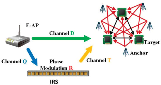
Figure 1.
PWSN with IRS.
Here, we define as the set of IRS reflective units. Then, the number of IRS units is . We employ the diagonal matrix to indicate the reflection parameter, which is for convenient calculation. Each element represents the reflection parameter of the rth unit, where is the reflectivity coefficient and is the phase shift. Consider a perfection reflection, in which ; thus, we can only control for phase modulation. However, such control is not continuous but discrete instead due to cost and hardware constraints. In this case, we can only select finite discrete phase values, defined as . Here, we employ as the phase shift interval and B is the number of bits of IRS. Then, all the phase shifts comes from .
For localization purpose, PWSN contains two kinds of nodes, which are anchors and targets. Nodes with known position information are called anchors. The nodes without position information are the targets. The set of anchors is , while the set of targets is . Here, we define that the position of the ith target point is , and the position of the pth anchor is . The distance between target i and target w is , where . Similarly, the distance between target i and anchor p is . The IRS uses phase modulation to control the energy wave from the E-AP to active the targets and anchors. The anchor broadcasts a signal to the target when it is powered up. Then, the targets locate themselves based on the wireless information.
Note that the nodes of PWSN are equipped with small chips and the processing capacities are quite low. In this case, such nodes can only process simple tasks, e.g., short modulation, communication and localization algorithm. The processing capacity of E-AP is much larger than the nodes. Thus, it can gather and maintain the location information of the nodes, and also controls the Tx power and sends the control information for IRS. For IRS, the processing resource is limited. According to the relationship among E-AP and the nodes, IRS can received the command of E-AP and execute such a command for phase modulation.
2.2. Wireless Propagation Model
The wireless propagation model contains two parts. The first one is the wireless power transfer from the E-AP to the passive sensor nodes. Part of the wireless waves are reflected by the IRS. On the node side, the nodes harvest energy from the wireless waves, including the reflected waves and directly transmitted waves. Here, the E-AP transmit a single-antenna signal x to the nodes, and the signal propagation is formulated as:
where is the received signal of the nth node from the E-AP; is the channel information of the downlink signal from the E-AP to the nth node; and is the noise, which is a zero mean normal distribution with variance . As presented in Figure 1, is the directed channel from the E-AP directly to the nth node and is the indirected channel from E-AP to the nodes, where is the channel matrix from the E-AP to the IRS; is the phase modulation control matrix of the IRS; and is the channel matrix from the IRS to the nth node. The overall channel matrix from E-AP to node n containing IRS is formulated as .
The second part is the propagation for localization. During this part, anchors start to transmit signals to the target nodes after harvesting sufficient energy from E-AP. When the nth anchor transmits signal to the ith target, the received signal of the ith target is
where indicates the channel from the nth anchor to the ith target, is the actual distance from the nth anchor to the ith target, and is the noise, which follows a normal distribution with zero mean and variance of . Considering a float fading propagation channel, the channel function is written as:
where is the carrying frequency, is the flat fading factor, indicates the channel gain, and c is the light speed.
3. Localization Performance Analysis
The Cramér–Rao lower bound (CRLB), which is called the optimal estimation indicator for any unbiased estimator, is widely used for the localization performance analysis. It is the inverse form of the Fisher information matrix (FIM), and the covariance of the unbiased estimator error should not be lower than the CRLB. For CRLB analysis, we first define the estimated vector, which is the target location vector , and define the observations, which are the wireless signals. Then, the likelihood function based on and observations are constructed. The FIM is the partial derivative of the likelihood functions, and the form is attained according to the chain rule:
where is the observation matrix, which is the partial derivative of the observation functions, is a diagonal matrix in which each element is , and is the range intensity, which indicates the signal-to-noise ratio (SNR) on the receiver end. In addition, can be also indicated as the sum of the geometric relationship between the target and anchors, which is called anchor–target geometry. Thus, we employ to represent the arrival angle from the anchor to target. Thus, we use FIM to analyze the localization performance for the PWSN using IRS.
3.1. FIM for Single Target
According to the above definition of FIM, we first derive the FIM form of the PWSN for a single target. Then, we extend the formulation to multiple targets and further to the cooperative localization. For a single target scenario, there is only one target node with unknown position and all the other passive nodes have known positions. Here, we define this target vector . Then, we set the observation vector , which are the received signal vector from all anchors:
where , and is the target received signal from the ith anchor.
The likelihood function of the observation vector conditioned on is expressed as:
where is the probability function for the observation noise. Thus, the covariance of should satisfy the following inequality:
where is the Fisher information matrix (FIM) of , and is defined as the CLRB. The FIM is expressed as
where is the partial derivative of , and is the score function. We set the partial derivative of the score function with respect to the position as :
According to the chain rule, for each , , we have:
where is the direction vector and is the receiving angle of the pth anchor connected to the target. Then, we have:
where , and indicates the power level of noise . For a single target scenario, the FIM consists of the SNR and the anchor–target geometry is indicated in (27). Note that represents the signal propagation from the anchor to the target and the harvest power attained from E-AP via the combined channel of free space and the modulated reflected channel by IRS. Note that the FIM indicates the impacts of power level of the signal noise on the node sides, which results from the variance of the noise. Such formulation is also applicable for other noise distributions due to the variance calculation nature of FIM.
3.2. Multiple Target
The multi-target localization is the extension of the single target scenario. Thus, we employ the form of to attain the FIM of the multi-target. Considering the multiple targets, we have targets and anchors. Then, we define:
where indicates the ith target. Then, we set the observation vector to indicate the received signals of the targets. Accordingly, the FIM is extended from the single target scenario, which is:
where we set to be the ith row and kth column submatrix in . The matrix is denoted as:
Note that when , is independent of the kth node position. Therefore, , . When , is formulated as:
Then, the FIM is simplified as:
Thus, of the multi-target localization is a diagonal matrix, in which each element is the FIM for single target localization.
3.3. Cooperative Localization
When the number of anchors are not enough for high-precision multiple target localization, the targets may transmit the wireless signals to each other. Then, they locate themselves based on the ranging information from other targets and anchors, which is called cooperative localization. In this case, the overall FIM should contain the form between the targets. First, we re-construct the observation vector, which includes the observations of the anchors and also the observations among the targets:
where is the received signal vector of all targets from the anchors, is the vector of signals received by all targets from other targets. The vectors and are expressed as
where , , and . Signal is the ith target received signal from the pth anchor. Signal is the wth target received signal from the ith target. Since the ith target does not propagate signals to itself, we define .
The likelihood function of the observation vector conditioned on is expressed as:
where we define .
The FIM is expressed as
where is the partial derivative of and is the score function. According to Equation (19), the score function can be expressed as
where is the score function of the received signals from anchors and is the score function of the received signals from targets. We set the partial derivative of the score function with respect to the position as , where . We have
According to the chain rule, for each , , we have:
where is the direction vector and is the receiving angle of the pth anchor connected to the ith target. According to Equation (20), we can obtain the target node that receives the FIM from the anchor.
where we set to be the ith row and kth column submatrix in . The matrix is denoted as:
Note that when , is independent of the position of the kth node. Therefore, . When , received by the ith target from the anchors is related to the ith target position, and is formulated as:
Since the received signals are independent of each other and , Equation (26) is expressed as:
where and indicates the power level of noise . Therefore, FIM is shown as:
Similarly, we assume that the partial derivative of the score function with respect to position is , where . Then, we have:
where for any and , we obtain it using the chain rule:
where is the direction vector and is the receiving angle of the qth target connected to the ith target. According to the spatial geometric relationship of the reception angle between nodes, . Thus, the relationship between the direction vector and is expressed as
According to Equation (20), we attain the FIM of the mutual transmission signals among the targets:
where is a block matrix in . In addition, is formulated as:
When , the received signals are independent of each other and , is expressed as:
Since the Tx power of the target nodes are different, . Meanwhile, when , the received signal of the ith target is correlated with the position of both ith targets. Therefore, is formulated:
Thus, the FIM of the cooperative localization contains the FIM for multi-target localization and the FIM among target cooperative localization. As observed above, the cooperative localization among targets may not always benefit the the localization performance since the localization error may propagate throughout the whole network. However, on the other hand, more targets contribute more observations for localization. Then, the overall performance is improved in general.
Note that although CLRB is used for denoting the estimation limits of the localization, CRLB is still a matrix instead of a quantified metric such as mean squared error (MSE) or root mean squared error (RMSE). Then, we employ the trace of CLRB , which is also called spatial position error bound (SPEB) as the quantification metric of positioning accuracy. Then, SPEB is expressed as:
where is the SPEB. Then, the localization optimization problem, which is the phase modulation problem in this paper, is to achieve the minimum .
4. Phase Modulation
As observed from , the localization accuracy of the PWSN highly relies on the received power of the nodes, and the received power depends on the wireless signal beam from the E-AP. The only parameter that can be adapted in the PWSN is the phase shifts in IRS. Thus, the phase modulation, which controls the phase shifts, is the key strategy to achieve the optimal localization performance. We can adapt the phase shift vector of the RIS reflective unit , where is an rth reflective unit phase shift. However, phase modulation is an integer programming problem, which is hard to solve. Here, we employ two common effective solutions for integer programming as the phase modulation strategies, which includes the approximation (AP) method and genetic algorithm (GA). Note that due to the constrained processing capacity of IRS, the proposed phase modulation strategies are implemented in the E-AP for iterative calculation. Then, the E-AP sends the final solutions to the IRS as commands, and the IRS executes solutions to achieve the optimal phase modulation.
4.1. Approximation
The approximation method first derives the optimal solution considering the parameters are continuous, and then discrete, to attain the final solution. Since the localization accuracy highly relies on the received power of the PWSN nodes, AP approaches the maximum received power and then the optimal localization is attained. Considering that the Tx power of E-AP is constant , the received power of each node is simplified as the channel gain:
In this case, the phase modulation matrix of IRS is the only variable that affects the node’s received power. Here, the amplitude of the channel is negatively correlated with the distance. Then, . Neglecting the with minimum amplitude and , which is independent of , Equation (37) can be expressed as:
When the adapted signals match the channel, in which in Equation (38), the node received power attains the maximum level, where indicates the imaginary part of a complex value. Such a continuous solution is converted into the nearest discrete approximation as:
where . Then, the final solution is attained.
4.2. Genetic Algorithm
Note that AP may not achieve the actual optimal solution since several relaxations are involved. Genetic algorithm (GA) is an efficient tool for integer programming and it can achieve optimal results with sufficient searching space and iterations. In addition, the formulation of the minimum is too complicated, while GA is good at solving such complicated problems.
Here, we employ as the fitness function and generate initial chromosomes for the first generation. Each chromosome is one of the phase shift combinations of the IRS. Then, we put these chromosomes into to evaluate the fitness and choose the best suits. For the real implementations, we choose 20% of the best suit chromosomes for further reproduction, crossover, and mutation processes. Then, we use the 20% of chromosomes to reproduce the children. During the reproduction, 60% of phase shifts are exchanged between chromosomes. Then, we randomly choose 10% of the phase shifts for mutation, in which the phase shifts are randomly changed to other values. In this case, we generate the other 80% of new chromosomes for the next iterations. Then, the GA is executed iteratively, while evaluating the fitness of the new chromosome set. After fixed iterations, we choose the best fit chromosome as the optimal solution.
5. Simulation
In this section, we set up several simulations to evaluate the performance of cooperative localization performance for PWSN with IRS. The playing area is a square region of . The E-AP, anchors, targets and IRS are deployed. The E-AP is located at the origin, and the center coordinates of the two IRSs are set to (50, 0) and (50,50). Here, all nodes are randomly deployed. The background noise is -150 dBm. The single antenna of E-AP emits 2.4 GHz electromagnetic waves with a Tx power of 30 dBm. The reflectivity coefficient of IRS is 1 and each unit has uniformly distributed phase shift . Then, each phase modulation unit has different phase modulations . The element spacing of IRS is . Considering all the channel information is known, and we implement the AP and GA to control the IRS, the simulation uses 400 Monte-Carlo runs in each simulation and averages the SPEB results for comparison. Note that since the single target and multiple target localization performances are quite similar to the cooperative localization mode, and the FIM of cooperative localization contains the forms of single and multiple target localizations, we evaluate the cooperative localization performance.
5.1. IRS Element Evaluation
Firstly, we evaluate the impacts of the IRS units for localization accuracy. The IRS units determine the harvested energy from E-AP and further influence the localization accuracy. Since the number of IRS units is adaptable, we evaluate the impacts on the localization accuracy. The IRS unit number is set from 100 to 1000. First, we formulate the SPEB optimized by phase modulation and SPEB without IRS in Figure 2. There are 5 anchors and 15 targets. We set a sample size of each algorithm and the number of iterations for GA.
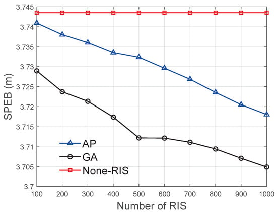
Figure 2.
SPEB with different numbers of RIS.
We observe that the SPEBs in Figure 2 decrease as the number of IRS units grows. On one hand, a large number of IRS units mean that more wireless energy waves can be reflected. With more attained power for each node, the SPEBs are increased accordingly. In addition, the channel adaptation capability is increased accordingly with more IRS units. Then, the proposed phase modulation strategies are applied. The SPEB of applying the AP algorithm is higher than GA but smaller than PWSN without RIS. The GA attains the smallest SPEB.
5.2. IRS Phase Value Evaluation
The phase modulation performance also depends on the number of phase shift values for each unit. If the number of phase shifts are sufficiently large, it is quite possible to achieve continuous optimal performance. Here, we apply the bit value to indicate the number of phase shifts, e.g., controlling for phase shifts is 2 bit. Then, we evaluate the bit impact for localization performance. We adapt the bit value from 1 to 4. The results are presented in Figure 3. The SPEB of GA is much smaller than AP and the PWSN without IRS. Meanwhile, when the bit number exceeded 3, the positioning accuracy was almost stable, which indicates that it is not necessary to control more bits of IRS, since the SPEBs remain the same and the complexities are increased dramatically. The main reason is that controlling 2 bits can approaching the optimal value. Controlling more bits may only lead to fine adaptation of the channel, which is not significant for localization performance improvement.
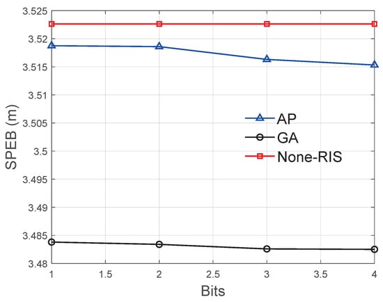
Figure 3.
SPEB with different bit numbers of IRS.
5.3. Node Number Evaluation
Then, the number of target nodes are also evaluated. We set the number of IRS units and the number of chromosomes for each algorithm to . Then, we set the number of iterations for GA as . The results are depicted in Figure 4.
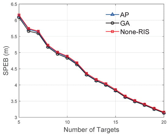
Figure 4.
SPEB with different number of nodes.
As shown in Figure 4, we observe that the SPEB of PWSN decreases when the number of targets is increased from 5 to 20. The SPEB of applying GA is much smaller than AP and the SPEB without IRS. This indicates that the SPEB decreases as the number of target increase, which means that the number of targets plays a dominant role in cooperative localization. This is because more targets contribute more observations. Then, the FIM attains more sub-matrixes for each target, and the SPEB is improved significantly. Note that such results are similar to the non-cooperative multiple target localizations, in which more anchors provide more observations to improve the SPEBs. In addition, compared with Figure 2 and Figure 3, the improvement of Figure 4 is more significant, which indicates that the localization performance highly relies on the number of observations instead of the signal power of the nodes.
5.4. NLoS Evaluation
IRS can improve the channel and avoid the NLoS propagation. Here, we compare the SPEB improvement rate using IRS for PWSN. The SPEB improvement rate is the ratio of the SPEB using IRS and without IRS. We also compare AP and GA. This simulation contains 5 anchors and 15 targets, and the number of iterations is . During the simulation, there is an obstacle between E-AP and the nodes, but there is no obstacle between E-AP and IRS, or between IRS and the nodes. Therefore, channel is NLoS with fading coefficient , while is LOS with fading coefficient .
The SPEB improvement rates are illustrated in Figure 5. With the same number of IRS, the SPEB improvement rate is larger in the NLoS case than in the LOS case. Note that these results do not indicate that more power is obtained in the NLoS case than in the LoS case, but rather indicates a significant improvement in the NLoS case. The SPEB improvement rate of the GA algorithm is much larger than AP. In addition, as presented in Figure 2 and Figure 3, the SPEB absolute improvements are not significant in the LoS case. However, the results in Figure 5 demonstrate that the phase shifts mainly improve the NLoS localization performance, which is the main difficult problem for wireless localization systems.
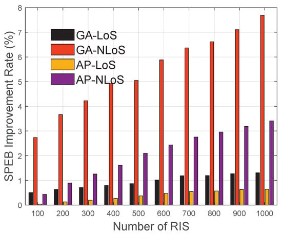
Figure 5.
SPEB with different numbers of RIS in NLOS.
5.5. Energy Efficiency Evaluation
Here, we also adapt the Tx power of E-AP and evaluate the impacts on SPEBs. Since the Tx power determines the harvest energy of each node in PWSN, the localization accuracy highly relies on such harvested energy. We adapt the power level from 0.8 W to 1.5 W, and the SPEB changes are depicted in Figure 6. We compare the performance of AP and GA. The results indicate that with the same Tx power level, GA attains a lower SPEB. On the other hand, GA is more energy efficiency than AP if the system attempts to achieve a certain localization accuracy.
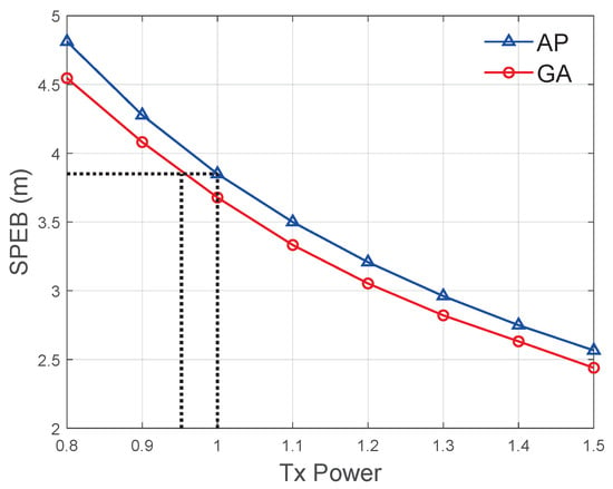
Figure 6.
SPEB with different Tx power level of E-AP.
6. Conclusions
In this paper, we provides the FIM formulation for PWSN with IRS. To attain the cooperative localization analyzing model, we firstly attain the single target and multiple target localization models. The FIM clearly indicates the relationship between the phase modulation and localization accuracy. Thus, we propose AP and GA solutions for optimal phase modulation. The proposed algorithms are evaluated via extensive simulations. The results indicate that with IRS, the localization accuracy can be significantly improved, especially in the NLoS propagations. In addition, the localization performance using GA is much better than AP. In this state, our work mainly focus on the theoretical analysis and simulations. In future work, we will implement our proposed strategies on the real IRS-based PWSN system to evaluate the localization performance.
Author Contributions
Conceptualization of PWSN using RIS, D.L. and S.C.; CRLB analysis and methodology, Z.L.; algorithm design, D.L. and Y.Z.; simulations, D.L. and S.C.; paper modifications, S.J. All authors have read and agreed to the published version of the manuscript.
Funding
This work was partially supported by the National Nature Science Foundation of China (No. 62171484), Zhuhai Fundamental and Application Research (No. ZH22017003210006PWC), the Open Research Fund of State Key Laboratory of Space-Ground Integrated Information Technology under grant NO. 2018_SGIIT_KFJJ_ST_01.
Data Availability Statement
Not applicable.
Conflicts of Interest
The authors declare no conflict of interest.
References
- Huang, J.; Zhou, Y.; Ning, Z.; Gharavi, H. Wireless Power Transfer and Energy Harvesting: Current Status and Future Prospects. IEEE Wirel. Commun. 2019, 26, 163–169. [Google Scholar] [CrossRef] [PubMed]
- Zafari, F.; Gkelias, A.; Leung, K.K. A Survey of Indoor Localization Systems and Technologies. IEEE Commun. Surv. Tutor. 2019, 21, 2568–2599. [Google Scholar] [CrossRef]
- Alrajeh, N.A.; Bashir, M.; Shams, B. Localization Techniques in Wireless Sensor Networks. Int. J. Distrib. Sens. Netw. 2013, 9, 304628. [Google Scholar] [CrossRef]
- Patwari, N.; Ash, J.; Kyperountas, S.; Hero, A.; Moses, R.; Correal, N. Locating the nodes: Cooperative localization in wireless sensor networks. IEEE Signal Process. Mag. 2005, 22, 54–69. [Google Scholar] [CrossRef]
- Bansal, R. The Future of Wireless Charging [AP-S Turnstile]. IEEE Antennas Propag. Mag. 2009, 51, 153. [Google Scholar] [CrossRef]
- Chang, Z.; Wu, X.; Wang, W.; Chen, G. Localization in Wireless Rechargeable Sensor Networks Using Mobile Directional Charger. In Proceedings of the 2015 IEEE Global Communications Conference (GLOBECOM), San Diego, CA, USA, 6–10 December 2015; pp. 1–6. [Google Scholar] [CrossRef]
- Vyas, R.; Lakafosis, V.; Tentzeris, M. Wireless remote localization system utilizing ambient RF/solar power scavenging RFID tags. In Proceedings of the 2010 IEEE MTT-S International Microwave Symposium, Anaheim, CA, USA, 23–28 May 2010; pp. 1764–1767. [Google Scholar] [CrossRef]
- El Assaf, A.; Zaidi, S.; Affes, S.; Kandil, N. Efficient Node Localization in Energy-Harvesting Wireless Sensor Networks. In Proceedings of the 2015 IEEE International Conference on Ubiquitous Wireless Broadband (ICUWB), Montreal, QC, Canada, 4–7 October 2015; pp. 1–7. [Google Scholar] [CrossRef]
- Zhao, Y.; Li, X.; Xia, M. Cooperative Localization in Wireless Powered Communication Network. In Proceedings of the ICC 2021-IEEE International Conference on Communications, Montreal, QC, Canada, 14–23 June 2021; pp. 1–6. [Google Scholar] [CrossRef]
- Huang, C.; Zappone, A.; Alexandropoulos, G.C.; Debbah, M.; Yuen, C. Reconfigurable Intelligent Surfaces for Energy Efficiency in Wireless Communication. IEEE Trans. Wirel. Commun. 2019, 18, 4157–4170. [Google Scholar] [CrossRef]
- Strinati, E.C.; Alexandropoulos, G.C.; Sciancalepore, V.; Di Renzo, M.; Wymeersch, H.; Phan-Huy, D.T.; Crozzoli, M.; D’Errico, R.; De Carvalho, E.; Popovski, P.; et al. Wireless Environment as a Service Enabled by Reconfigurable Intelligent Surfaces: The RISE-6G Perspective. In Proceedings of the 2021 Joint European Conference on Networks and Communications & 6G Summit (EuCNC/6G Summit), Porto, Portugal, 8–11 June 2021; pp. 562–567. [Google Scholar] [CrossRef]
- Zhang, H.; Di, B.; Song, L.; Han, Z. Reconfigurable Intelligent Surfaces Assisted Communications With Limited Phase Shifts: How Many Phase Shifts Are Enough? IEEE Trans. Veh. Technol. 2020, 69, 4498–4502. [Google Scholar] [CrossRef]
- Mohjazi, L.; Muhaidat, S.; Abbasi, Q.H.; Imran, M.A.; Dobre, O.A.; Di Renzo, M. Battery Recharging Time Models for Reconfigurable Intelligent Surfaces-Assisted Wireless Power Transfer Systems. IEEE Trans. Green Commun. Netw. 2021, 6, 1173–1185. [Google Scholar] [CrossRef]
- Tran, N.M.; Miftahul Amri, M.; Park, J.H.; In Kim, D.; Choi, K.W. Beam Scanning Methods for Multi-Antenna Wireless Power Transfer with Reconfigurable Intelligent Surface. In Proceedings of the 2021 IEEE 22nd International Workshop on Signal Processing Advances in Wireless Communications (SPAWC), Lucca, Italy, 27–30 September 2021; pp. 626–630. [Google Scholar] [CrossRef]
- Li, K.; Naderi, Y.; Muncuk, U.; Chowdhury, K.R. iSurface: Self-Powered Reconfigurable Intelligent Surfaces with Wireless Power Transfer. IEEE Commun. Mag. 2021, 59, 109–115. [Google Scholar] [CrossRef]
- Tran, N.M.; Amri, M.M.; Park, J.H.; Kim, D.I.; Choi, K.W. Multi-Device Charging RIS-Aided Wireless Power Transfer Systems. In Proceedings of the 2021 International Conference on Information and Communication Technology Convergence (ICTC), Jeju Island, Republic of Korea, 20–22 October 2021; pp. 839–844. [Google Scholar] [CrossRef]
- Yang, H.; Yuan, X.; Fang, J.; Liang, Y.C. Reconfigurable Intelligent Surface Aided Constant-Envelope Wireless Power Transfer. IEEE Trans. Signal Process. 2021, 69, 1347–1361. [Google Scholar] [CrossRef]
- Dai, W.; Shen, Y.; Win, M.Z. Distributed Power Allocation for Cooperative Wireless Network Localization. IEEE J. Sel. Areas Commun. 2015, 33, 28–40. [Google Scholar] [CrossRef]
- Shen, Y.; Dai, W.; Win, M.Z. Power Optimization for Network Localization. IEEE/ACM Trans. Netw. 2014, 22, 1337–1350. [Google Scholar] [CrossRef]
Disclaimer/Publisher’s Note: The statements, opinions and data contained in all publications are solely those of the individual author(s) and contributor(s) and not of MDPI and/or the editor(s). MDPI and/or the editor(s) disclaim responsibility for any injury to people or property resulting from any ideas, methods, instructions or products referred to in the content. |
© 2022 by the authors. Licensee MDPI, Basel, Switzerland. This article is an open access article distributed under the terms and conditions of the Creative Commons Attribution (CC BY) license (https://creativecommons.org/licenses/by/4.0/).