
Artificial Neural Network-Based Parameter Identification Method for Wireless Power Transfer Systems

Abstract
:1. Introduction
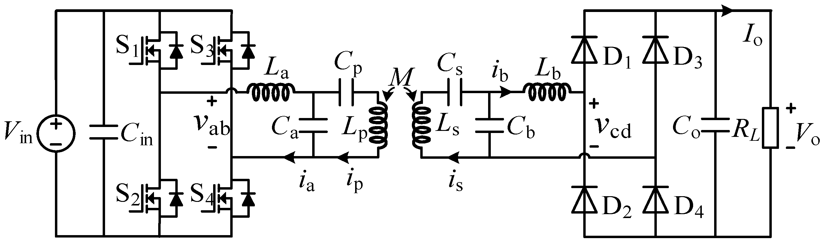
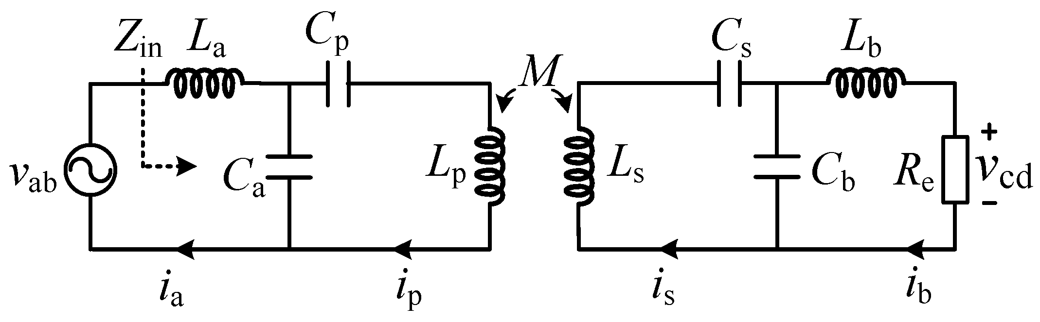
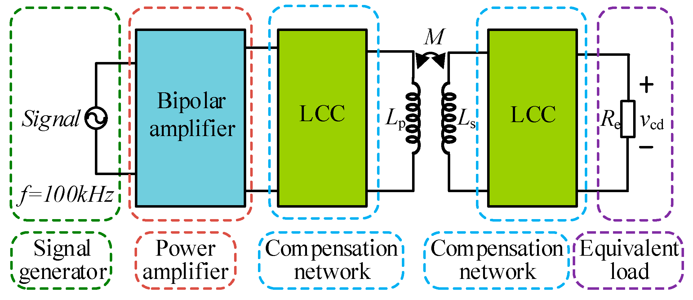
2. System Modelling
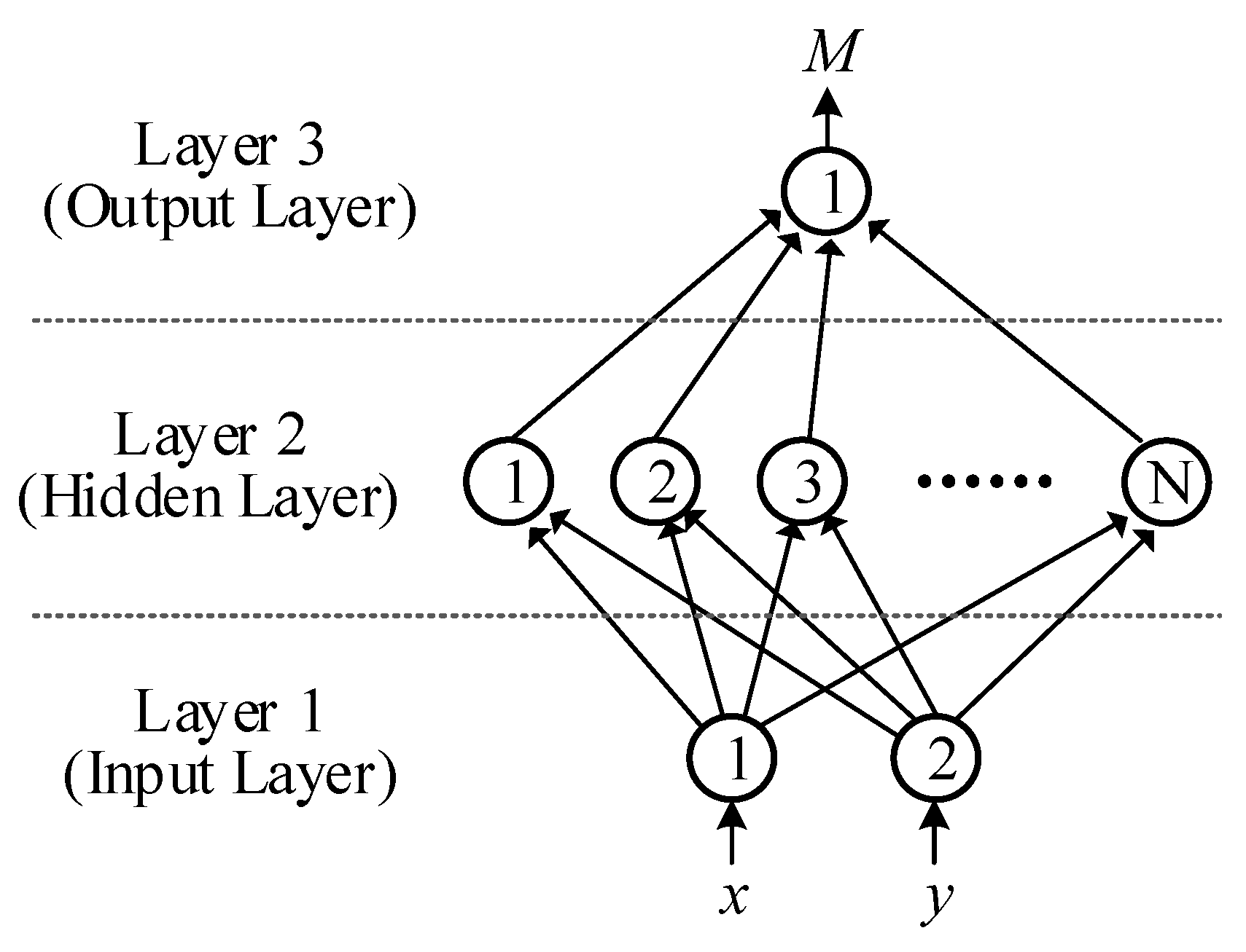
3. Artificial Neural Network
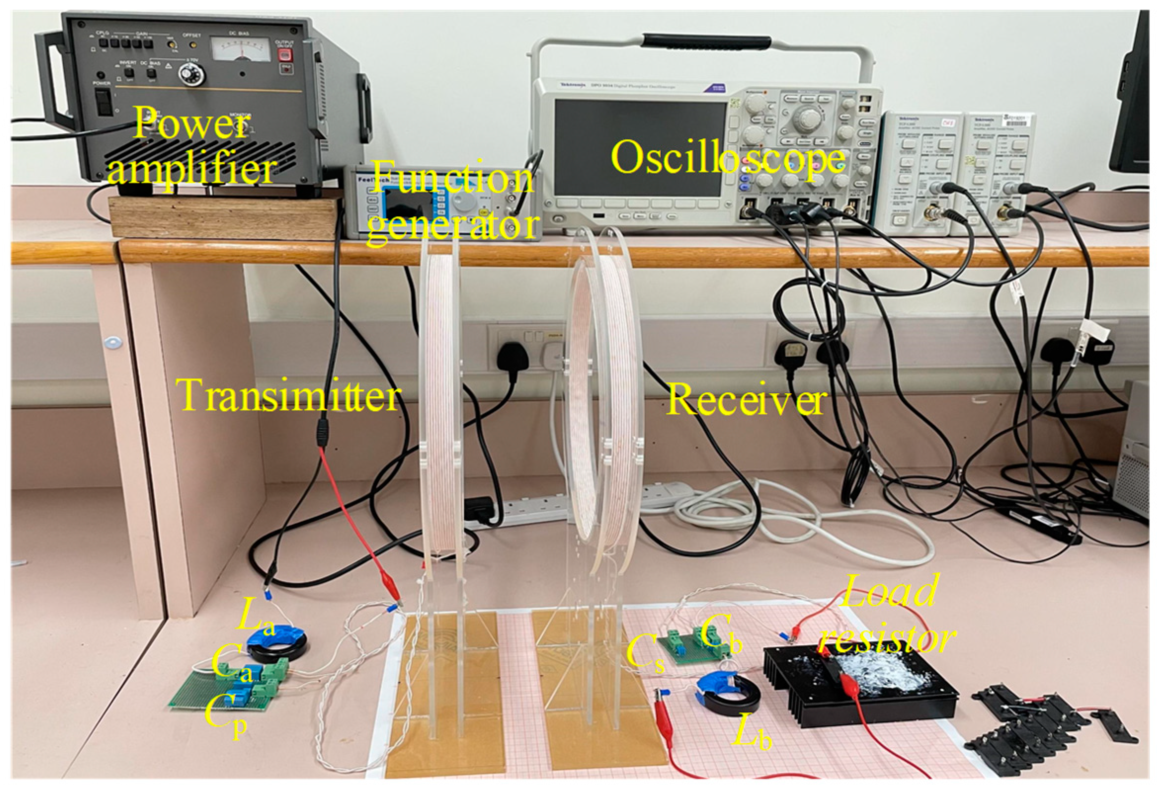
4. Experimental Validation
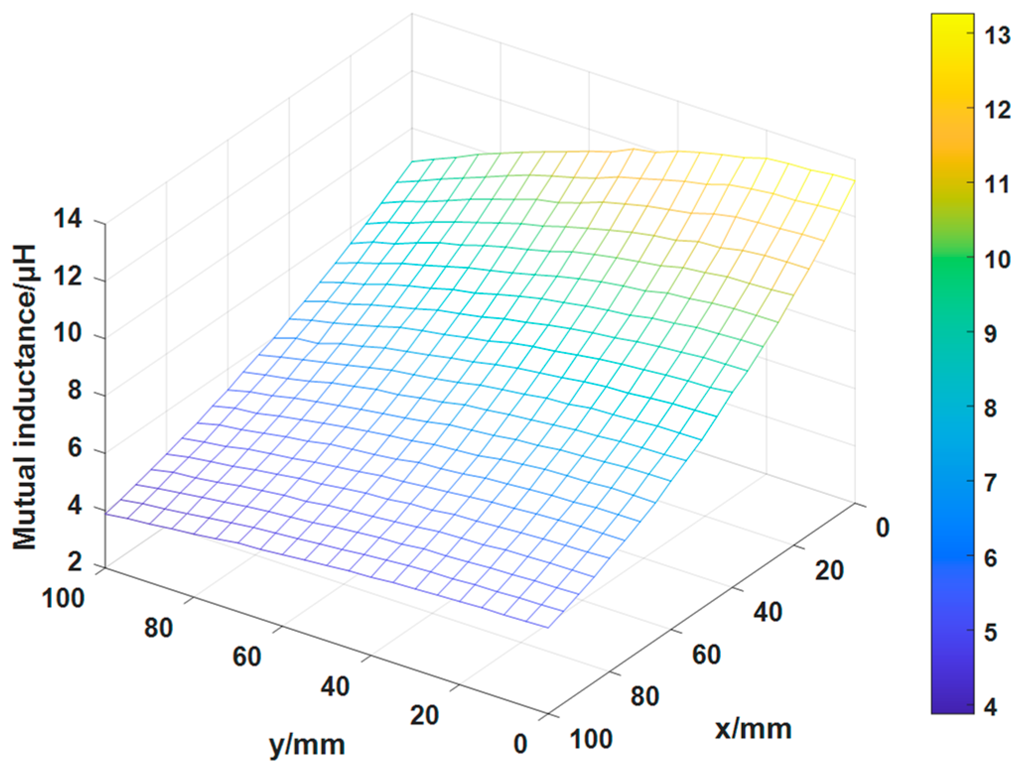
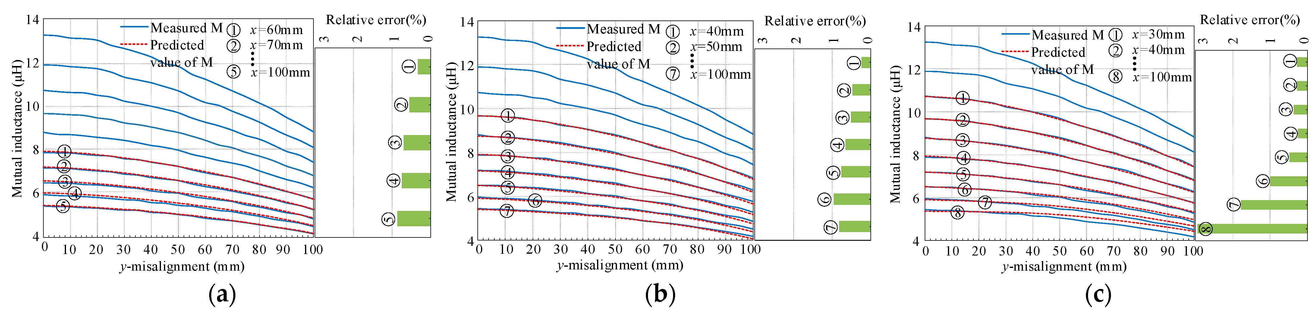
4.1. Mutual Inductance
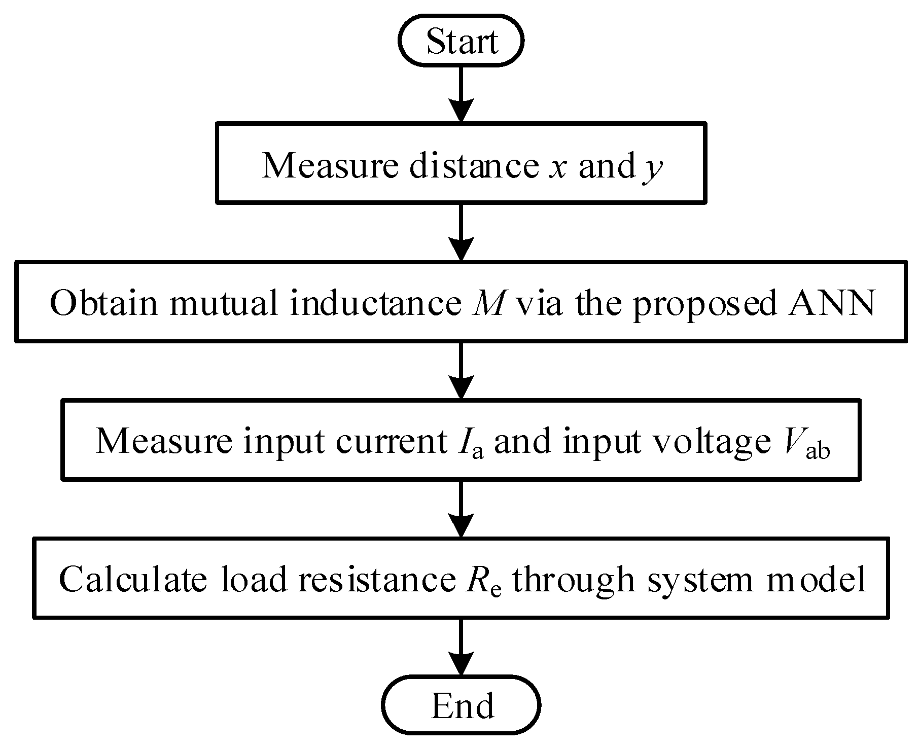
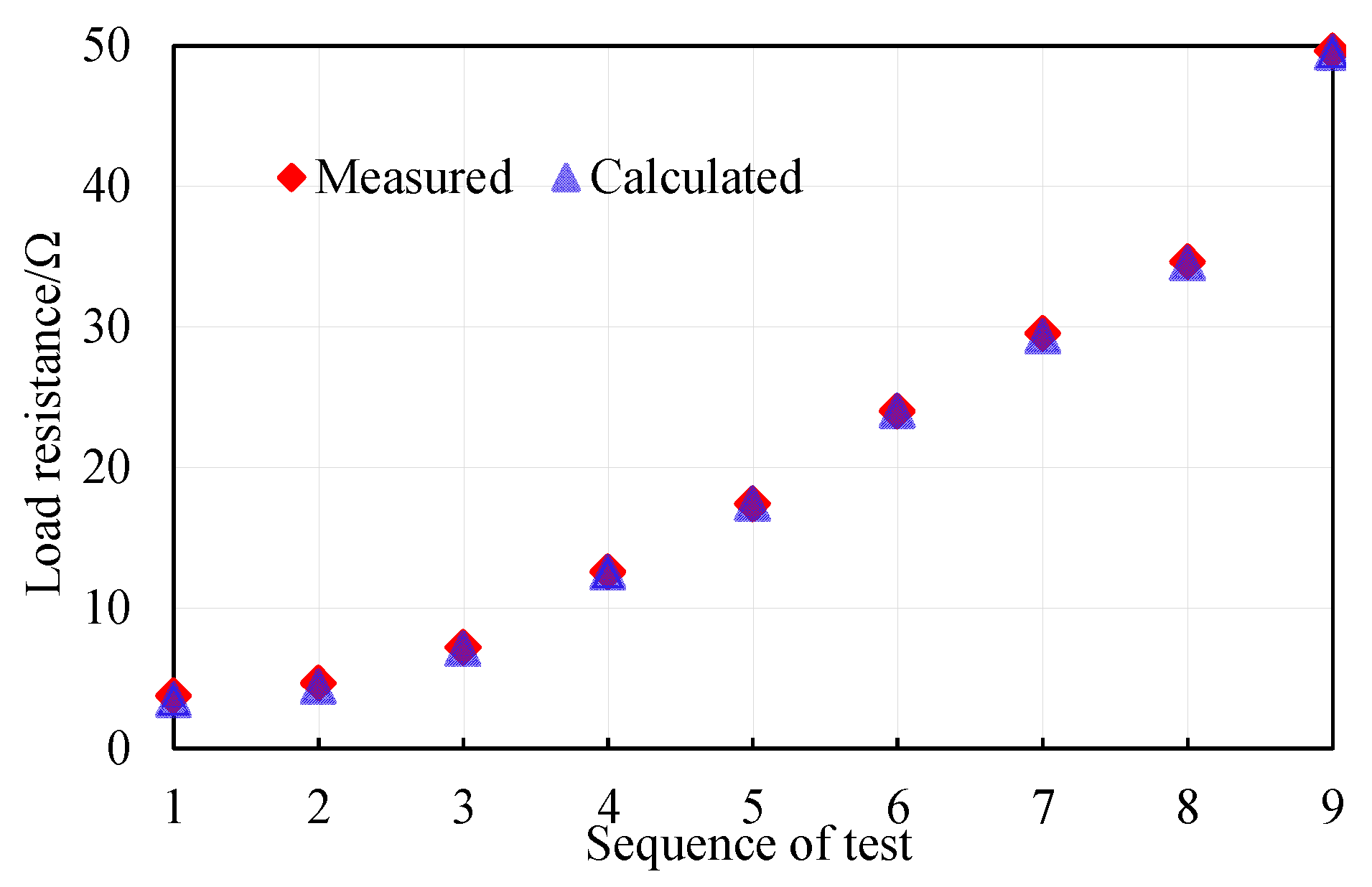
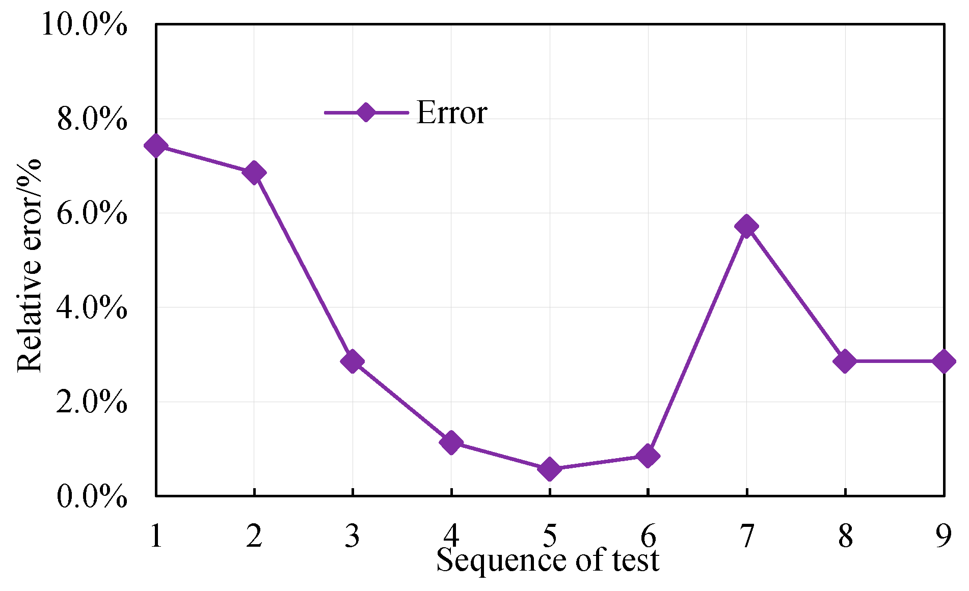
4.2. Load Calculation of WPT System
5. Discussion
6. Conclusions
Author Contributions
Funding
Institutional Review Board Statement
Informed Consent Statement
Data Availability Statement
Conflicts of Interest
Nomenclature
| Vin | DC input voltage |
| v1 | Equivalent voltage source on the secondary side |
| Cin | Input capacitor |
| Si | ith MOSFET in the inverter |
| Di | ith diode in the rectifier |
| Lp | Transmitter coil |
| La | Primary additional inductor |
| Ca | Primary parallel capacitor |
| Cp | Primary series capacitor |
| Ls | Receiver coil |
| Lb | Secondary additional inductor |
| Cs | Secondary series capacitor |
| Cb | Secondary parallel capacitor |
| Co | Output filter capacitor |
| RL | Load resistance |
| vab | AC voltage at the output of inverter |
| ia | Current through the primary additional inductor |
| ip | Current through the transmitter coil |
| M | Mutual inductance between transmitter coil and receiver coil |
| is | Current through the receiver coil |
| ib | Current through the secondary additional inductor |
| vcd | AC voltage at the input of rectifier |
| Io | Current through the load |
| Zin | Input impedance at the inverter output |
| Zref | Reflected impedance |
| ω | Resonant angular frequency |
| Re | Equivalent load resistance |
References
- Zhang, Z.; Pang, H.; Georgiadis, A.; Cecati, C. Wireless Power Transfer—An Overview. IEEE Trans. Ind. Electron. 2019, 66, 1044–1058. [Google Scholar] [CrossRef]
- Ahmad, A.; Alam, M.S.; Chabaan, R. A Comprehensive Review of Wireless Charging Technologies for Electric Vehicles. IEEE Trans. Transp. Electrif. 2018, 4, 38–63. [Google Scholar] [CrossRef]
- Beh, H.Z.; Neath, M.; Boys, J.T.; Covic, G.A. An Alternative IPT Pickup Controller for Material Handling Using a Current Doubler. IEEE Trans. Power Electron. 2018, 33, 10135–10147. [Google Scholar] [CrossRef]
- Vu, V.; Tran, D.; Choi, W. Implementation of the Constant Current and Constant Voltage Charge of Inductive Power Transfer Systems with the Double-Sided LCC Compensation Topology for Electric Vehicle Battery Charge Applications. IEEE Trans. Power Electron. 2018, 33, 7398–7410. [Google Scholar] [CrossRef] [Green Version]
- Zhang, W.; White, J.C.; Abraham, A.M.; Mi, C.C. Loosely Coupled Transformer Structure and Interoperability Study for EV Wireless Charging Systems. IEEE Trans. Power Electron. 2015, 30, 6356–6367. [Google Scholar] [CrossRef]
- Hou, J.; Chen, Q.; Zhang, Z.; Wong, S.-C.; Tse, C.K. Analysis of Output Current Characteristics for Higher Order Primary Compensation in Inductive Power Transfer Systems. IEEE Trans. Power Electron. 2018, 33, 6807–6821. [Google Scholar] [CrossRef]
- Huang, Z.; Wong, S.; Tse, C.K. Design of a Single-Stage Inductive-Power-Transfer Converter for Efficient EV Battery Charging. IEEE Trans. Veh. 2017, 66, 5808–5821. [Google Scholar] [CrossRef]
- Wang, X.; Xu, J.; Leng, M.; Ma, H.; He, S. A Hybrid Control Strategy of LCC-S Compensated WPT System for Wide Output Voltage and ZVS Range with Minimized Reactive Current. IEEE Trans. Ind. Electron. 2021, 68, 7908–7920. [Google Scholar] [CrossRef]
- Chow, J.P.; Chung, H.S.; Cheng, C. Use of Transmitter-Side Electrical Information to Estimate Mutual Inductance and Regulate Receiver-Side Power in Wireless Inductive Link. IEEE Trans. Power Electron. 2016, 31, 6079–6091. [Google Scholar] [CrossRef]
- Zhong, W.; Hui, S.Y. Reconfigurable Wireless Power Transfer Systems with High Energy Efficiency over Wide Load Range. IEEE Trans. Power Electron. 2018, 33, 6379–6390. [Google Scholar] [CrossRef]
- Wang, Y.; Shi, G.; Yao, Y.; Alonso, J.M.; Weifeng, G.; Liu, X.; Xu, D. A Double-T-Type Compensation Network and Its Tuning Method for IPT System. IEEE Trans. Ind. Electron. 2017, 53, 4757–4767. [Google Scholar] [CrossRef]
- Liu, F.; Chen, K.; Zhao, Z.; Li, K.; Yuan, L. Transmitter-Side Control of Both the CC and CV Modes for the Wireless EV Charging System with the Weak Communication. IEEE Trans. Emerg. Sel. 2018, 6, 955–965. [Google Scholar] [CrossRef]
- Darvish, P.; Mekhilef, S.; Illias, H.A.B. A Novel S–S–LCLCC Compensation for Three-Coil WPT to Improve Misalignment and Energy Efficiency Stiffness of Wireless Charging System. IEEE Trans. Power Electron. 2021, 36, 1341–1355. [Google Scholar] [CrossRef]
- Yue, R.; Wang, C.; Li, H.; Liu, Y. Constant-Voltage and Constant-Current Output Using P-CLCL Compensation Circuit for Single-Switch Inductive Power Transfer. IEEE Trans. Power Electron. 2021, 36, 5181–5190. [Google Scholar] [CrossRef]
- Song, K.; Li, Z.; Jiang, J.; Zhu, C. Constant Current/Voltage Charging Operation for Series–Series and Series–Parallel Compensated Wireless Power Transfer Systems Employing Primary-Side Controller. IEEE Trans. Power Electron. 2018, 33, 8065–8080. [Google Scholar] [CrossRef]
- Li, Z.; Liu, H.; Tian, Y.; Liu, Y. Constant Current/Voltage Charging for Primary-Side Controlled Wireless Charging System Without Using Dual-Side Communication. IEEE Trans. Power Electron. 2021, 36, 13562–13577. [Google Scholar] [CrossRef]
- Li, Y.; Hu, J.; Li, X.; Chen, F.; Xu, Q.; Mai, R.; He, Z. Analysis, Design, and Experimental Verification of a Mixed High-Order Compensations-Based WPT System with Constant Current Outputs for Driving Multistring LEDs. IEEE Trans. Ind. Electron. 2020, 67, 203–213. [Google Scholar] [CrossRef]
- Kavimandan, U.D.; Mahajan, S.M.; van Neste, C.W. Analysis and Demonstration of a Dynamic ZVS Angle Control Using a Tuning Capacitor in a Wireless Power Transfer System. IEEE Trans. Emerg. Sel. 2021, 9, 1876–1890. [Google Scholar] [CrossRef]
- Huang, Z.; Wong, S.; Tse, C.K. An Inductive-Power-Transfer Converter with High Efficiency Throughout Battery-Charging Process. IEEE Trans. Power Electron. 2019, 34, 10245–10255. [Google Scholar] [CrossRef]
- Guo, Y.; Zhang, Y.; Zhang, W.; Wang, L. Battery Parameter Identification Based on Wireless Power Transfer System with Rectifier Load. IEEE Trans. Ind. Electron. 2021, 68, 6893–6904. [Google Scholar] [CrossRef]
- Hui, S.Y.R.; Zhong, W.; Lee, C.K. A Critical Review of Recent Progress in Mid-Range Wireless Power Transfer. IEEE Trans. Power Electron. 2014, 29, 4500–4511. [Google Scholar] [CrossRef] [Green Version]
- Zhong, W.X.; Hui, S.Y.R. Maximum Energy Efficiency Tracking for Wireless Power Transfer Systems. IEEE Trans. Power Electron. 2015, 30, 4025–4034. [Google Scholar] [CrossRef] [Green Version]
- Tang, X.; Zeng, J.; Pun, K.P.; Mai, S.; Zhang, C.; Wang, Z. Low-Cost Maximum Efficiency Tracking Method for Wireless Power Transfer Systems. IEEE Trans. Power Electron. 2018, 33, 5317–5329. [Google Scholar] [CrossRef]
- Wang, X.; Xu, J.; Ma, H.; He, S. Inductive Power Transfer Systems with Digital Switch-Controlled Capacitor for Maximum Efficiency Point Tracking. IEEE Trans. Ind. Electron. 2021, 68, 9467–9480. [Google Scholar] [CrossRef]
- Wang, Z.; Li, Y.; Sun, Y.; Tang, C.; Lv, X. Load Detection Model of Voltage-Fed Inductive Power Transfer System. IEEE Trans. Power Electron. 2013, 28, 5233–5243. [Google Scholar] [CrossRef]
- Jiwariyavej, V.; Imura, T.; Hori, Y. Coupling Coefficients Estimation of Wireless Power Transfer System via Magnetic Resonance Coupling Using Information from Either Side of the System. IEEE Trans. Emerg. Sel. 2015, 3, 191–200. [Google Scholar] [CrossRef]
- Hu, J.; Zhao, J.; Cui, C. A Wide Charging Range Wireless Power Transfer Control System with Harmonic Current to Estimate the Coupling Coefficient. IEEE Trans. Power Electron. 2021, 36, 5082–5094. [Google Scholar] [CrossRef]
- Yin, J.; Lin, D.; Parisini, T.; Hui, S.Y. Front-End Monitoring of the Mutual Inductance and Load Resistance in a Series–Series Compensated Wireless Power Transfer System. IEEE Trans. Power Electron. 2016, 31, 7339–7352. [Google Scholar] [CrossRef]
- Yin, J.; Lin, D.; Lee, C.; Hui, S.Y.R. A Systematic Approach for Load Monitoring and Power Control in Wireless Power Transfer Systems without Any Direct Output Measurement. IEEE Trans. Power Electron. 2015, 30, 1657–1667. [Google Scholar] [CrossRef]
- Guo, Y.; Zhang, Y. Secondary Side Voltage and Current Estimation of Wireless Power Transfer Systems. IEEE Trans. Ind. Appl. 2022, 58, 1222–1230. [Google Scholar] [CrossRef]
- Roshani, S.; Jamshidi, M.B.; Mohebi, F.; Roshani, S. Design and Modeling of a Compact Power Divider with Squared Resonators Using Artificial Intelligence. Wireless Pers Commun. 2021, 117, 2085–2096. [Google Scholar] [CrossRef]
- Li, Y.; Dong, W.; Yang, Q.; Zhao, J.; Liu, L.; Feng, S. An Automatic Impedance Matching Method Based on the Feedforward-Backpropagation Neural Network for a WPT System. IEEE Trans. Ind. Electron. 2019, 66, 3963–3972. [Google Scholar] [CrossRef]
- Fu, N.; Deng, J.; Wang, Z.; Wang, W.; Wang, S. A Hybrid Mode Control Strategy for LCC–LCC- Compensated WPT System with Wide ZVS Operation. IEEE Trans. Power Electron. 2022, 37, 2449–2460. [Google Scholar] [CrossRef]
- Villegas-Mier, C.; Rodriguez-Resendiz, J.; Álvarez-Alvarado, J.M.; Rodriguez-Resendiz, H.; Herrera-Navarro, A.; Rodríguez-Abreo, O. Artificial neural networks in MPPT algorithms for optimization of photovoltaic power systems: A review. Micromachines 2021, 12, 1260. [Google Scholar] [CrossRef]
- Rodríguez-Abreo, O.; Rodríguez-Reséndiz, J.; Fuentes-Silva, C.; Hernández-Alvarado, R.; Falcón, M.D.C.P.T. Self-Tuning Neural Network PID with Dynamic Response Control. IEEE Access 2021, 9, 65206–65215. [Google Scholar] [CrossRef]
- Zhao, S.; Fu, H. An artificial neural network-based approach for the impedance modeling of piezoelectric energy harvesting devices. Int. J. Numer. Model. Electron. Netw. Devices Fields 2018, 31, 2333. [Google Scholar] [CrossRef]


| Error | Experiment 1 | Experiment 2 | Experiment 3 |
|---|---|---|---|
| Maximum error | 0.87% | 0.96% | 2.93% |
| Average error | 0.64% | 0.63% | 0.91% |
| Symbol | Parameter | Value |
|---|---|---|
| Vab | Input AC voltage | 10 V |
| f | Frequency | 100 kHz |
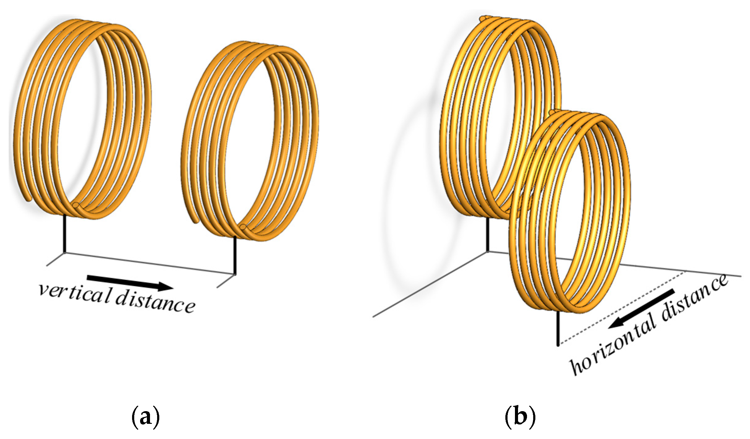
| x | Vertical distance | 0–100 mm |
| y | Horizontal distance | 0–100 mm |
| La | Primary additional inductor | 21.2 μH |
| Ca | Primary parallel capacitor | 119.4 nF |
| Cp | Primary series capacitor | 55.26 nF |
| Lp | Transmitter coil inductor | 67.2 μH |
| Ls | Receiver coil inductor | 67.2 μH |
| Cs | Secondary series capacitor | 55.2 nF |
| Cb | Secondary parallel capacitor | 120 nF |
| Lb | Secondary additional inductor | 21.2 μH |
Publisher’s Note: MDPI stays neutral with regard to jurisdictional claims in published maps and institutional affiliations. |
© 2022 by the authors. Licensee MDPI, Basel, Switzerland. This article is an open access article distributed under the terms and conditions of the Creative Commons Attribution (CC BY) license (https://creativecommons.org/licenses/by/4.0/).
Share and Cite
He, L.; Zhao, S.; Wang, X.; Lee, C.-K. Artificial Neural Network-Based Parameter Identification Method for Wireless Power Transfer Systems. Electronics 2022, 11, 1415. https://doi.org/10.3390/electronics11091415
He L, Zhao S, Wang X, Lee C-K. Artificial Neural Network-Based Parameter Identification Method for Wireless Power Transfer Systems. Electronics. 2022; 11(9):1415. https://doi.org/10.3390/electronics11091415
Chicago/Turabian StyleHe, Liangxi, Sheng Zhao, Xiaoqiang Wang, and Chi-Kwan Lee. 2022. "Artificial Neural Network-Based Parameter Identification Method for Wireless Power Transfer Systems" Electronics 11, no. 9: 1415. https://doi.org/10.3390/electronics11091415
APA StyleHe, L., Zhao, S., Wang, X., & Lee, C.-K. (2022). Artificial Neural Network-Based Parameter Identification Method for Wireless Power Transfer Systems. Electronics, 11(9), 1415. https://doi.org/10.3390/electronics11091415