Article

Low-Dimensional-Approximate Model Based Improved Fuzzy Non-Singular Terminal Sliding Mode Control for Rigid-Flexible Manipulators

1
School of Mechanical and Electrical Engineering, Central South University, Changsha 410083, China
2
The State Key Laboratory of High Performance and Complex Manufacturing, Changsha 410083, China
3
Physical Science and Technology College, Yichun University, Yichun 336000, China
*
Authors to whom correspondence should be addressed.
Electronics 2022, 11(8), 1263; https://doi.org/10.3390/electronics11081263
Submission received: 29 March 2022 / Revised: 14 April 2022 / Accepted: 14 April 2022 / Published: 16 April 2022
(This article belongs to the Special Issue Advanced Research in Electromagnetic Devices for Electric Vehicles)

Abstract

:
The dynamic characteristics of rigid-flexible manipulators involve complex rigid-flexible coupling phenomena, which essentially comprise a nonlinear distributed parameter system with infinite degrees of freedom. Consequently, it results in challenges to the manipulator’s precise positioning. This study combined a state feedback module and a fuzzy non-singular terminal sliding mode to suppress vibration and deformation. Using the improved fuzzy strategy and non-singular terminal sliding mode control, an adaptive dynamic supplementary control law is proposed. The results based on MATLAB simulation and a built hardware experiment show that this method is effective and superior. While realizing the accurate positioning of the end of the manipulator, the vibration of the end of the flexible arm is significantly suppressed. This method has a high tracking performance, which enables accurate positioning of the manipulator terminal and provides strong robustness under the action of bounded external interference.

1. Introduction

A rigid-flexible manipulator has safe operation characteristics, such as a high weight ratio, high efficiency, an energy-saving operation model, and low inertia. At present, most researchers are focusing on flexible manipulators. However, because rigid-flexible manipulators [1,2,3,4] have stronger operability and versatility, higher payload, and lower total cost than traditional flexible manipulators [5,6], a number of studies have examined them. They have been widely used in several application domains such as medicine and space, for example [7,8,9,10,11,12,13,14,15]. However, due to the rigid-flexible coupling of the structure and the inherent nonlinear dynamics, rigid-flexible manipulators are a type of highly coupled nonlinear time-varying system with distributed parameters [16]. Due to the relatively poor structural damping and pole position of the flexible manipulator, it is easily deflected and vibrated in the process of motion, which results in great challenges to the perfect tracking control of the rigid-flexible manipulators under a bounded input. Therefore, studies on the control of the rigid-flexible manipulators have important theoretical and practical significance.
In order to achieve accurate positioning and end vibration suppression control of rigid and flexible manipulators, several control methods have been proposed, such as linear control [17,18,19], general nonlinear control [20,21], adaptive control [22,23], fuzzy control [17,18,19,20,21,22,23,24,25], and sliding mode control methods [26,27,28,29,30].
The sliding mode control (SMC) is considered to be an efficient control method, and has the advantages of simple structure, strong robustness, and easy implementation [24,25,26]. The chattering problem has always been the bottleneck that restricts the application of the sliding mode control in practical systems. The boundary layer method [31,32,33] can efficiently reduce and suppress chattering. This method continuously performs discontinuous control at the expense of some control performance [34,35,36]. Gao Weibing [37] proposed the concept of the reaching law, which reduces chattering by adjusting the reaching law’s parameters. However, its convergence time is too long. As a novel continuous sliding mode control method—high-order sliding mode—its control concept consists of indirectly adding high-frequency switching control to the high-order derivatives of sliding mode variables, which greatly reduces the chattering of control variables without affecting the characteristics of sliding mode control [38,39,40]. For instance, Levant et al. [41] designed an arbitrary high-order sliding mode controller using the spiral switching algorithm and differential estimation technology. Fermm et al. [42] proposed a second-order sliding mode control law using the time-optimal approach. Chiacchiarini et al. [43] proposed a high-order sliding mode control method based on the stability theory. However, the high-order sliding mode control has the problem of complex parameter adjustment and difficulty in precision. Therefore, a hybrid controller composed of intelligent system theory, adaptive control theory, and synovial control was proposed. In [44], the fuzzy control was combined with the approach rate. This method suppresses the vibration by adjusting the approach rate coefficient according to the current state of the system. The authors in [45] introduced the interferometer into the sliding mode control algorithm and achieved satisfactory results. In [46], the switching function is differentiated. The advantage of this treatment is that the control item has a higher-order derivative and the vibration suppression effect is improved. Due to a large number of coefficients in the sliding mode surface, the approaching law and switching function were proposed in [47,48,49,50]. However, this method is time-consuming and complex because it adjusts parameters one at a time. In addition, it is sometimes difficult to adjust the optimal parameters. Therefore, the particle swarm optimization differential evolution algorithm was proposed for real-time dynamic optimization of these parameters. In [51,52,53,54], the high-order SMC (HOSMC) was proposed to eliminate or reduce chattering. In order to improve HOSMC, several time-convergence and chattering reduction algorithms have been proposed, such as the suboptimal algorithm, twisting algorithm, and STA [55,56].
The non-singular terminal sliding mode control [57] (NTSMC) has been recently studied. It solves the singularity problem of the existing terminal sliding mode control directly via the sliding mode design, by purposefully changing the switching function [58], and performing the global non-singular control of the system. In addition to being able to get rid of singular problems, it also inherits finite time convergence characteristics. Compared with the traditional linear sliding mode control, it can make the control system converge to the desired trajectory in a limited time, and it has high steady-state accuracy. It is especially suitable for high-speed and high-precision control. Although the long convergence time and insufficient stability problems exist in non-singular terminal sliding mode control, the method can still efficiently suppress chattering.
This paper further improves its merits by introducing a fuzzy strategy [59]. At present, two approaches exist for combining the fuzzy algorithm and non-singular terminal sliding mode control (FNTSMC) in order to alleviate chattering: (1) the switching function and its derivative are the inputs of the fuzzy controller, and the sliding mode control quantity is obtained by fuzzy reasoning [24,25,28]; (2) the sliding mode variable is the input of the fuzzy controller, and the output is the approximation of the switching function coefficient K. The fuzzy reasoning rules are summarized as follows [44,59]. If the motion state of the system is far from the switching plane, the control gain is selected to be larger in order to accelerate the approaching speed of the system. Otherwise, the control gain is reduced in order to reduce the input torque chattering. In addition to the equivalent control component, the nonlinear switching term also includes switching gain and a residual term. Although these two fuzzy methods have high robustness, their control effect is easily limited by the number of designed fuzzy control rules, and cannot simultaneously meet the requirements of response speed and control accuracy.
Based on these considerations, this study examined the control problem of rigid-flexible manipulators based on the low-dimensional approximate model [60]. For the non-minimum phase system, the output redefinition [61] is used to redefine the output observer. From the perspective of the compensation control law, the improved fuzzy non-singular terminal sliding mode control (IFNTSMC) method is used, and the idea of the variable universe is introduced to adaptively adjust the scope of the input and output universe. On the premise of not adding fuzzy rules, the approximation performance and control quality of the fuzzy control system is improved, and the adaptive dynamic compensation control law is achieved, so that the system can improve the convergence speed under the condition of overcoming jitter. Moreover, it can ensure that the system has a better tracking performance and strong robustness even in the case where bounded external interference exists.
The main contributions of this study are summarized as follows:
(1)
For the low-order model belonging to the non-minimum phase system, the output redefinition [61] is used to redefine the output observer, which not only keeps the system’s main characteristics, but also reduces the degree of freedom of the system on the premise of the unknown and clear loss of the solution accuracy. This results in great convenience for the system analysis and controller design.
(2)
A novel fuzzy control strategy is proposed. It uses the improved fuzzy method and introduces the variable universe concept in order to adaptively adjust the range of the input and output universe. Without adding fuzzy rules, the control law is dynamically compensated in real time, so as to improve the convergence speed of the system, under the condition of overcoming jitter.
(3)
Combining the redefined output observer of the proposed low-order model with the fuzzy non-singular terminal slide controller, the convergence speed is improved, and the chattering problem of sliding mode control is reduced. The accurate positioning of the end of the rigid-flexible manipulators and the suppression of residual vibration are then achieved.

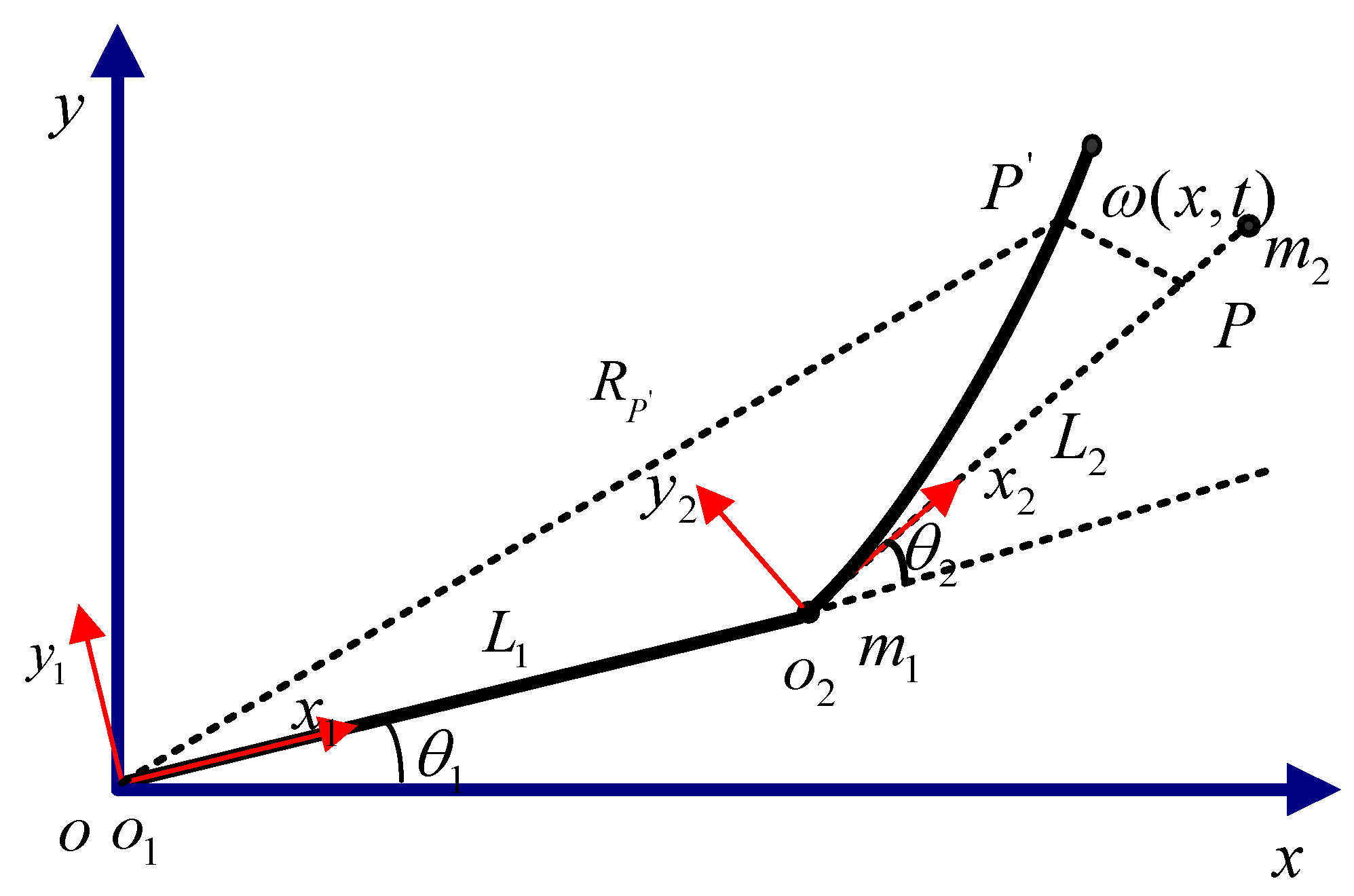
2. Dynamic Modeling of the Rigid-Flexible Manipulators System

The rigid-flexible link manipulator system studied in this paper is shown in Figure 1, and its detailed description is provided in [62].
In Figure 1, o - x y represents the inertial coordinate frame, and o 1 - x 1 y 1 and o 2 - x 2 y 2 are the moving coordinate frames with origin at the hubs of links 1 and 2, respectively. In addition, m 1 is the mass of the second hubs, m 2 is the mass of the tip load, θ 1 and θ 2 are respectively the revolving angles of the two links with respect to their frames, L 1 and L 2 are respectively the length of the two links, ω ( x , t ) is the transverse elastic displacement, and x is a spatial vector along with o 2 x 2 . According to the results obtained in [62], the low-dimensional approximation model of the rigid-flexible manipulators system (cf. Figure 1) can be obtained.
M [ θ ¨ q ¨ ] + [ F 1 ( θ , q , θ ˙ , q ˙ ) F 2 ( θ , q , θ ˙ , q ˙ ) ] + [ E 1 θ ˙ E 2 q ˙ + K q ] = [ u 0 ]
where M is the positive-definite mass matrix, θ = ( θ 1 , θ 2 ) T represents the angle of the two rotational joint, q = ( q 1 , q 2 ) T denotes the generalized coordinates of flexible link, [ F 1 ( θ , q , θ ˙ , q ˙ ) , F 2 ( θ , q , θ ˙ , q ˙ ) ] T is the vector of nonlinearities due to Coriolis and centrifugal forces, E 1 = [ μ 1 0 0 μ 2 ] represents the positive damping matrix, E 2 = [ δ 1 0 0 δ 2 ] is the structure damping matrix, and K is the positive-definite stiffness matrix.
The mass matrix is written as M ( θ , q ) = [ M θ θ M θ q M T θ q M q q ] , and M 1 ( θ , q ) = [ H θ θ H q θ H θ q H q q ] is set. Both sides of Equation (1) are then multiplied by M 1 , and finally the dynamic Equation can be expressed as in Equations (2) and (3).
θ ¨ = H θ θ ( F 1 ( θ , q , θ ˙ , q ˙ ) + E 1 θ ˙ ) H θ q ( F 2 ( θ , q , θ ˙ , q ˙ ) + E 2 q ˙ + K q ) + H θ θ u
q ¨ = H θ q ( F 1 ( θ , q , θ ˙ , q ˙ ) + E 1 θ ˙ ) H q q ( F 2 ( θ , q , θ ˙ , q ˙ ) + E 2 q ˙ + K q ) + H θ q u
In order to better design the controller of the low-dimension approximate model of Equation (1), the output should be redefined and the input-output subsystem should be linearized.

3. Output Redefinition

In the process of control, it is necessary to ensure that the rigid-flexible manipulators can move along the given trajectory in a large range, and to suppress the elastic deformation and vibration when the system moves. The study in [63] shows that in the control of a flexible manipulator, when the end position is considered as the system output, the system is in a non-minimum phase. In order to overcome the problem of non-minimum phase system characteristics, the output redefinition method can be used. Therefore, the output observation of the end position of the redefined rigid-flexible manipulators system is given by:
{ y 1 = θ 1 y 2 = θ 2 + α arctan ( ω ( L 2 , t ) L 2 )
Due to the fact that the deformation is significantly smaller than the length of the flexible link:
arctan ( ω ( L 2 , t ) L 2 ) ω ( L 2 , t ) L 2
Equation (4) can be written as:
{ y 1 = θ 1 y 2 = θ 2 + α ω ( L 2 , t ) L 2 = θ 2 + α L 2 i = 1 2 Φ i ( x ) q i ( t )
where α is a variable having a value between −1 and +1.
The end position of the rigid-flexible manipulators is written in vector form:
y = θ + D q
y = [ y 1 , y 2 ] T ,   D = α L 2 [ 0 0 Φ 1 ( L 2 ) Φ 2 ( L 2 ) ]

4. Linearization of the Input and Output Subsystems

The dynamic model of the rigid-flexible manipulators system is composed of nonlinear differential equations that belong to a complex nonlinear system. In this section, the nonlinear feedback term or dynamic compensation term is introduced into the control law design, in order to linearize the nonlinear feedback of input and output. Different control laws of the system are based on the linear system theory. Therefore, it is necessary to linearize the rigid-flexible manipulators system.
The dynamic model of the rigid-flexible manipulators system has two inputs and four outputs that belong to the underactuated system. According to the input/output linearization method [64,65], the input and output subsystem of the rigid-flexible manipulators can be written as:
y ¨ = Γ ( α , θ , q , θ ˙ , q ˙ ) + Z ( α , θ , q ) u
where:
Γ ( α , θ , q , θ ˙ , q ˙ ) = ( H θ θ + D H q θ ) ( F 1 ( θ , q , θ ˙ , q ˙ ) + E 1 θ ˙ )   ( H θ q + D H q q ) ( F 1 ( θ , q , θ ˙ , q ˙ ) + E 2 q ˙ + K q )
Z ( α , θ , q ) = H θ θ + D H q θ
Let U = [ A T B T ] T , A = [ A 1 T A 2 T ] T = [ y T y ˙ T ] T and B = [ B 1 T B 2 T ] T = [ q T q ˙ T ] T , the equation of state of the system is then given by:
{ A ˙ 1 = A 2 A ˙ 2 = Γ ( α , θ , q , θ ˙ , q ˙ ) + Z ( α , θ , q ) u B ˙ 1 = B 2 B ˙ 2 = E ( θ , q , θ ˙ , q ˙ ) + H q θ u
where:
E ( θ , q , θ ˙ , q ˙ ) = H θ q ( F 1 ( θ , q , θ ˙ , q ˙ ) + E 1 θ ˙ ) H q q ( F 2 ( θ , q , θ ˙ , q ˙ ) + E 2 q ˙ + K q )
In Equation (10), A 1 and A 2 are respectively the inputs and output subsystems, and B 1   B 1 and B 2 B 2 are respectively the internal dynamic subsystems, such that:
{ A ˙ 1 = A 2 A ˙ 2 = ν
{ B ˙ 1 = B 2 B ˙ 2 = E ( θ , q , θ ˙ , q ˙ ) + H q θ Z 1 ( α , θ , q ) ( v Γ ( α , θ , q , θ ˙ , q ˙ ) )
where v  is the control quantity to be designed.

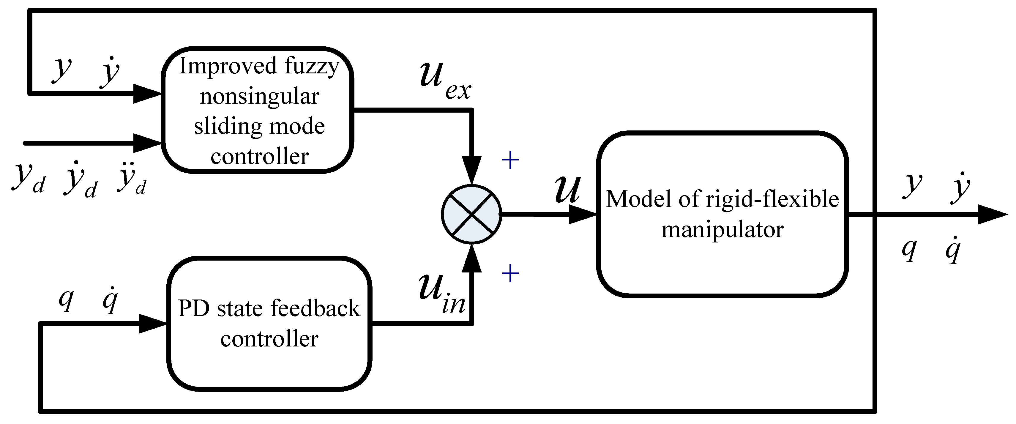
5. Controller Design

Because the rigid arm system is a minimum phase system, the asymptotic stability of the system can be guaranteed when the closed-loop control system is developed, so that the end trajectory of the system can be more easily determined. The determination of the end trajectory of the flexible arm is much more complex. The difficulty is that it is a non-minimum phase system. An important difference between a flexible arm and a rigid arm depends on whether there are internal dynamics. In the case of flexible arm movement, if the flexible deformation vibration is not suppressed, the internal dynamics of the manipulator become unstable. In the case of feedforward control, the instability of internal dynamics can easily lead to the divergence of calculated torque [66]. If feedback control is used, it leads to the instability of the closed-loop system. Due to the need to consider the characteristics of the dynamic model of the rigid-flexible manipulator system, there may be changes in the structural parameters, environmental changes, and component aging during operation. In the controller design, the designed output of the input-output subsystem should first follow the given trajectory. In addition, in order to ensure the stability of the internal dynamic subsystem, the following control structure (cf. Figure 2) is then proposed:
In Figure 2, u e x is the control quantity of the input and output subsystems, and u i n  is the control quantity of the internal dynamic subsystem.

5.1. Stabilization of Interconnected Subsystems Based on PD State Feedback

According to [67], the PD state feedback is used to stabilize the internal dynamic subsystem and make the flexible deformation A converge:
u i n = K q q + K q ˙ q ˙
The total input control quantity is given by:
u = u e x + u i n     = Ζ 1 ( α , θ , q ) ( y ¨ r + Λ e ˙ Γ ( α , θ , q , θ ˙ , q ˙ ) + ε sgn S + K s S ) + K q q + K q ˙ q ˙
By substituting Equations (7) and (9) into Equation (13), the following can be obtained:
{ Β ˙ 1 = Β 2 Β ˙ 2 = ( H q q K + H q θ K q ) Β 1 + ( H q q E 2 + H q θ K q ˙ ) Β 2 H q θ ( F 1 + E 1 θ ˙ ) H q q F 2 + H q θ ( Ζ 1 ( α , θ , q ) ( y ¨ r + Λ e ˙ Γ ( α , θ , q , θ ˙ , q ˙ ) + ε sgn S + K s S )
The internal dynamic subsystem is linearized at A and B such that Β 1 = 0 and Β 2 = 0 Β 1 = 0 and Β 2 = 0
Β ˙ = Β Β
where Π B = [ 0 I - H q q 0 K + H q θ 0 K q H q θ 0 K q ˙ ] , H i j 0 = H i j | Β 1 = 0 , Β 2 = 0 .
As long as appropriate control gains K q and K q ˙ are selected and Π B is a Hurwitz matrix, it can be known from [67] that the internal dynamic subsystem can maintain local asymptotic stability.

5.2. Design of Non-Singular Terminal Sliding Mode Controller

Compared with the asymptotic convergence of the linear sliding mode surface, the state of the system can reach the origin in a finite time along the terminal sliding mode surface, and has higher steady-state accuracy. In order to overcome the shortcomings of the sliding mode control based on the linear sliding mode surface, a non-singular terminal sliding mode in terminal sliding mode control is considered:
s = e + β e ˙ p / ν
where e = y d y is the deviation, y d represents the desired trajectory, β and p, v is the sliding surface parameter such that 2 > ( p / ν ) > 1 .
The exponential approach law S ˙ = ε sgn S K s S , which can be obtained according to Equations (7) and (18), is then considered.
S ˙ = e ˙ + β p v e ˙ p v 1 e ¨ = β p v e ˙ p v 1 ( y ¨ d y ¨ ) + e ˙ = β p v e ˙ p v 1 ( y ¨ d Γ ( α , θ , q , θ ˙ , q ˙ ) Ζ ( α , θ , q ) u e x ) + e ˙ = ε sgn S K s S
The control law can be obtained from Equation (19)
u e x = Z 1 ( α , θ , q ) ( y ¨ r [ β p v e ˙ ( p v 1 ) ] 1 ( ε sgn S K s S e ˙ ) Γ ( α , θ , q , θ ˙ , q ˙ ) )
where ε , K s and sgn ( S ) = [ sgn ( S 1 ) sgn ( S 2 ) ] T are similar to the previously defined parameters.
Similarly, the comprehensive control quantity of the system is given by:
u = Z 1 ( α , θ , q ) ( y ¨ r [ β p v e ˙ ( p v 1 ) ] 1 ( ε sgn S K s S e ˙ ) Γ ( α , θ , q , θ ˙ , q ˙ ) ) + K q q + K q ˙ q ˙

5.3. Design of Improved Fuzzy Non-Singular Terminal Sliding Mode Controller

The existing fuzzy non-singular terminal sliding mode control is fuzzy to the sliding mode index, the sliding mode index has strict parameter constraints, and the method is complex. However, the proposed improved fuzzy strategy does not require accurately knowing the relevant parameters of the sliding mode surface, and the direct real-time dynamic compensation control law is simple and easy to implement. The specific design is summarized as follows:
s and its differential s ˙ are first considered as the inputs of the fuzzy compensator, while its output is the control variation ∆ u, which can be calculated according to the designed rule base um, under the condition of satisfying s s ˙ < 0.
Let the fuzzy set be {PB = positive large PM = positive middle PS = positive small NS = negative small NM = negative middle NB = negative large}; the output rule base of the fuzzy compensator is then determined [68] (cf. Table 1).
The center of gravity method is used for fuzzy reasoning and fuzzy resolution. Finally, the improved non-singular fuzzy terminal sliding mode control law is expressed as:
u zong = u + u m
where u is similar to that in Equation (21).
The fuzzy and variable universes are then combined. The design process is summarized as follows.
The expansion factor of variable universe is combined with the fuzzy universe, and its expression is:
{ [ α D , α D ] = α [ D , D ] [ β Y , β Y ] = β [ Y , Y ]
where [−D,D] and [−Y,Y] respectively represent the initial universe of the fuzzy input and output, and α and β represent the scaling factor of the input and output, respectively.
Since the scaling factor is introduced into the fuzzy universe, the initial universe can be dynamically adjusted using the scaling factor. Through the real-time calculation of the system error, it can be deduced that, if the error is large, the universe will be expanded, and the sensitivity of the result will be reduced through fuzzy rules in order to reduce the dynamic error.
The important factor used to measure the effect of variable universe fuzzy control consists in accurately providing the scaling factor. The proposed design of the scaling factor is shown in Equations (24) and (25):
α ( ϑ ) = ( | ϑ | ϑ ) τ + ξ
β ( ϑ , ) = ( ϑ + ϑ ) τ + ξ
where α ( ϑ ) represents the expansion factor of the input universe, β ( ϑ , ) is the scaling factor of the output universe, ϑ represents the input, denotes the output, ξ is a minimal positive number, and τ > 0 .

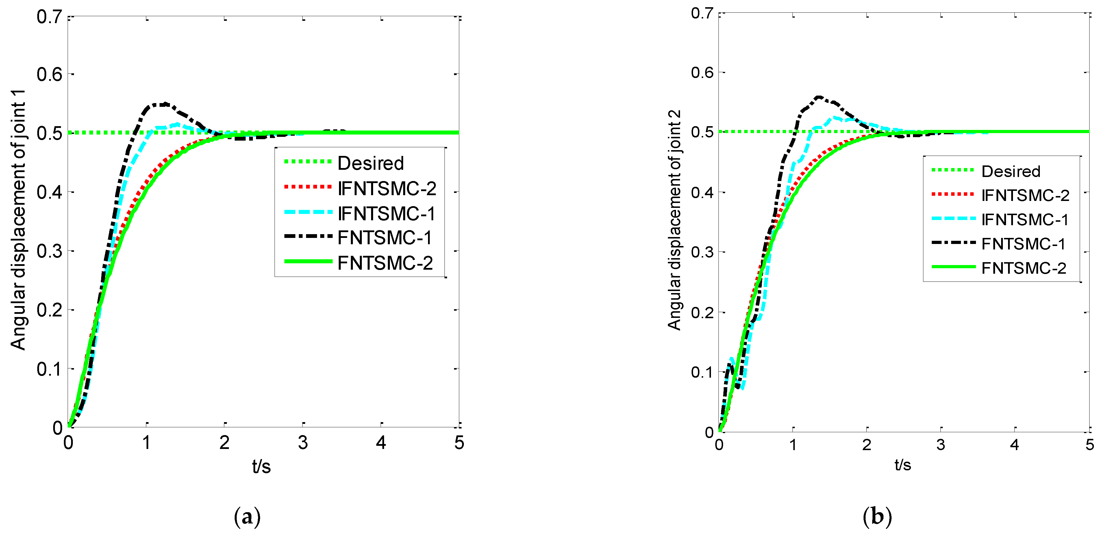
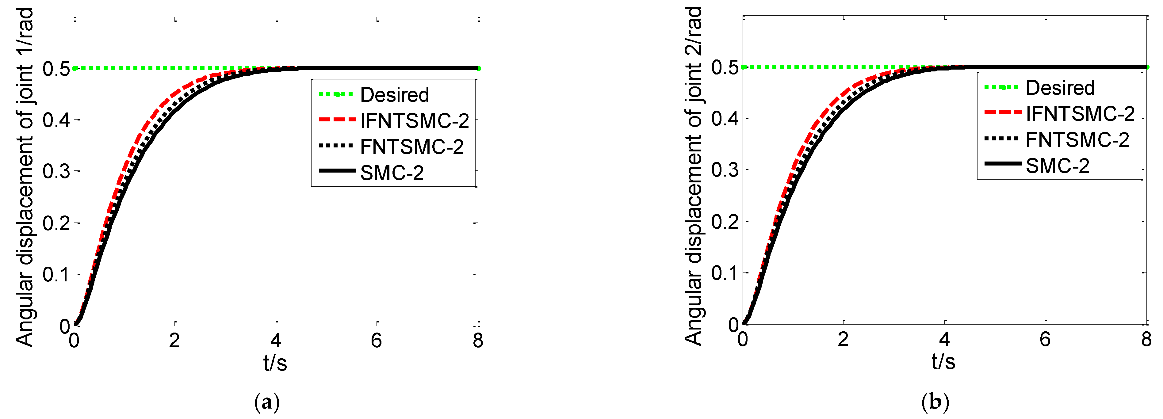
6. Simulation Analysis

Given the step signal y d = [ 0.5 0.5 ] T (in rad), the controller parameter of the second-order modal model is α = 0.65 , β = [ 0.9 0.9 ] , p = [ 9 9 ] , v = [ 7 7 ] , K s = d i a g [ 80 80 ] , ε = 0.01 . The controller parameter of the first-order modal model is α = 0.7 , β = [ 0.8 0.8 ] , p = [ 5 5 ] , v = [ 3 3 ] , K s = d i a g [ 65 65 ] , ε = 0.015 , with a sampling period of 2 milliseconds. The simulation results are shown in Figure 3, Figure 4 and Figure 5:
In Figure 3, Figure 4 and Figure 5, IFNTSMC-1 represents the improved fuzzy non-singular terminal sliding mode control of the first-order mode model, and IFNTSMC-2 denotes the improved fuzzy non-singular terminal sliding mode control of the second-order mode model.
The simulation results in Figure 3, Figure 4 and Figure 5 demonstrate that the performance and end vibration of the controller are further improved. In addition, the cumbersome manual parameter adjustment is avoided after the real-time dynamic optimization of the discourse domain with the improved fuzzy strategy. This also proves that the IFNTSM method is efficient, and it provides a basis for follow-up studies.
It can also be seen from the simulation results of the first-order modal model (IFNTSMC-1) in Figure 3, Figure 4 and Figure 5 that, compared with the FNTSMC method, the input torque jitter, joint response speed, adjustment time, and maximum amplitude at the end are much lower. However, compared with the second-order modal model (FNTSMC-2), the input torque jitter and the maximum amplitude at the end are still larger, which further verifies that the accuracy of the first-order modal model is lower than that of the second-order modal model. It is also demonstrated that it is necessary to study the approximate inertial manifold algorithm in order to reduce the dimension of the manipulator model.

7. Experimental Verification of the Fuzzy Non-Singular Terminal Sliding Mode Control for Low Dimensional Mode

7.1. Experimental Platform

Figure 6 presents the real figure model validation experiment platform, including joint 1, which is driven by the step motor and ball screw transmission, and installed in the guideway grating ruler of the mobile position measurement, and joint 2 and joint 3, which are driven by a servo motor and reducer. The servo motor end has an installed incremental code that can collect the motor movement. The angle is computed in real time. The deformation of the flexible arm of the manipulator can be obtained by collecting the deformation data with a dynamic strain gauge; therefore, the accurate position of the end can be obtained. The main parameters of the test bench are shown in Table 2 and Table 3.

7.2. Experimental Methods

The coordinate system was developed for the experimental platform (overlooking the experimental platform), as shown in Figure 7. The axis is perpendicular to the guide plane and parallel to the guide plane. Therefore, the initial end position of the rigid-flexible manipulators is (0.63, 0). In the written control system, the desired angle of the two joints is obtained by inverse calculation, and the corresponding control quantity of the motor is given by the corresponding control program until the target position is reached. An experiment is performed by a computer controller in the process of the program, in order to calculate the motor input control. Using the motor control card given as input to rotate the joints, and through the motor encoder real-time angular displacement of the two-joint acquisition and data acquisition instrument flexible arm, the change in the strain gauge value is calculated at the end of the real-time feedback to the computer, in order to control the deformation. During the experiment, the angular displacement of the two joints, the control input, and the deformation of the flexible arm end are saved in real time. Three sliding mode control algorithms (SMC, FNTSMC, and IFNTSMC) of the second-order modal model are used to verify and compare the results. The end coordinate positions of the experiment are (0.45 m, 0.41 m), and the expected angles of the two joints are determined as (28.130°, 29.868°) by inverse kinematic calculation.

7.3. Analysis of the Experimental Results

According to this control system and experimental methods, the end position control of rigid-flexible manipulators was experimentally studied. The experimental results are shown in Figure 8, Figure 9 and Figure 10 and Table 4.
It can be seen from Figure 8, Figure 9 and Figure 10 that the improved fuzzy non-singular terminal sliding mode control (IFNTSMC-2) has the most stable control amount, compared with the fuzzy non-singular terminal sliding mode control (FNTSMC-2) and sliding mode control (SMC-2), so that the motion is relatively stable, the deformation of the end is relatively small, and the response of joints 1 and 2 to the terminal is also faster. It can be seen from Figure 10 that the improved fuzzy non-singular terminal sliding mode controller (IFNTSMC-2) has the best control effect, compared with the fuzzy non-singular terminal sliding mode controller (FNTSMC-2) and sliding mode controller (SMC-2).

8. Conclusions

This study examined the control problem of a low-dimensional approximate model. The vibration and deformation of the rigid-flexible manipulators are suppressed by proposing an improved fuzzy non-singular terminal sliding mode controller. The dynamic compensation control law is used to improve the convergence speed of the system under disturbance. The simulation and experimental results demonstrate the superior performance of the proposed method, which can significantly suppress the residual vibration of the manipulator end and achieve its accurate positioning. Finally, the proposed method has a high tracking performance and strong robustness under the action of bounded external interference.

Author Contributions

Conceptual design, H.D. and L.X.; simulation and experiment, X.Q. and R.H.; data sorting, Y.Z. All authors have read and agreed to the published version of the manuscript.

Funding

This research was funded by the National Natural Science Foundation of China (61963036) and in part by the Project of State Key Laboratory of High Performance Complex Manufacturing, Central South University under Grant ZZYJKT2021-17.

Institutional Review Board Statement

Not applicable.

Informed Consent Statement

Not applicable.

Data Availability Statement

If necessary, you can ask the author for relevant data.

Acknowledgments

Thank you for the hardware experimental equipment provided by the State Key Laboratory of high performance and complex manufacturing, College of mechanical and electrical engineering.

Conflicts of Interest

The authors declare no conflict of interest.

References

  1. Zhao, Z.; He, X.; Ahn, C.K. Boundary disturbance observer-based control of a vibrating single-link flexible manipulator. IEEE Trans. Syst. Man Cybern. 2021, 51, 2382–2390. [Google Scholar] [CrossRef]
  2. Shawky, A.; Zydek, D.; Elhalwagy, Y.Z. Modeling and nonlinear control of a flexible-link manipulator. Appl. Math. Model. 2013, 37, 9591–9602. [Google Scholar] [CrossRef]
  3. Yang, H.; Yu, Y.; Yuan, Y.; Fan, X. Back-stepping control of two-link flexible manipulator based on an extended state observer. Adv. Space Res. 2015, 56, 2312–2322. [Google Scholar] [CrossRef]
  4. Karagülle, H.; Malgaca, L.; Dirilmiş, M. Vibration control of a two-link flexible manipulator. J. Vib. Control. 2017, 23, 2023–2034. [Google Scholar] [CrossRef]
  5. Liang, D.; Song, Y.; Sun, T.; Jin, X. Rigid flexible coupling dynamic modeling and investigation of a redundantly actuated parallel manipulator with multiple actuation modes. J. Sound Vib. 2017, 403, 129–151. [Google Scholar] [CrossRef]
  6. Congqing, W.; Pengfei, W.; Xin, Z.; Xiwu, P. Composite sliding mode control for a free-floating space rigid flexible coupling manipulator system. Int. J. Adv. Rob. Syst. 2013, 10, 124. [Google Scholar] [CrossRef] [Green Version]
  7. Gharooni, S.; Heller, B.; Tokhi, M.O. A new hybrid spring brakeorthosis for controlling hip and knee flexion in the swing phase. IEEE Trans. Neural Syst. Rehabil. Eng. 2001, 9, 106–107. [Google Scholar] [CrossRef]
  8. Kumar, R.; Berkelman, P.; Gupta, P. Preliminary experiments in cooperative human/robot force control for robot assisted microsurgical manipulation. In Proceedings of the 2000 ICRA. Millennium Conference. IEEE International Conference on Robotics and Automation. Symposia Proceedings, San Francisco, CA, USA, 24–28 April 2000; Volume 1, pp. 610–617. [Google Scholar]
  9. Ni, Z.; Liu, J.; Wu, Z. Identification of the state-space model and payload mass parameter of a flexible space manipulator using a recursive subspace tracking method. Chin. J. Aeronaut. 2019, 32, 513–530. [Google Scholar] [CrossRef]
  10. Meng, D.; Wang, X.; Xu, W. Space robots with flexible appendages: Dynamic modeling, coupling measurement, and vibration suppression. J. Sound Vib. 2017, 396, 30–50. [Google Scholar] [CrossRef]
  11. Li, Z.; Li, G.; Wu, X.; Kan, Z.; Su, H.; Liu, Y. Asymmetric Cooperation Control of Dual-Arm Exoskeletons Using Human Collaborative Manipulation Models. IEEE Trans. Cybern. 2021, 34, 264–271. [Google Scholar] [CrossRef]
  12. Su, H.; Qi, W.; Hu, Y.; Karimi, H.R.; Ferrigno, G.; Momi, E. An Incremental Learning Framework for Human-like Redundancy Optimization of Anthropomorphic Manipulators. IEEE Trans. Ind. Inf. 2020, 18, 1864–1872. [Google Scholar] [CrossRef]
  13. Su, H.; Qi, W.; Yang, C.; Sandoval, J.; Ferrigno, G.; De Momi, E. Deep Neural Network Approach in Robot Tool Dynamics Identification for Bilateral Teleoperation. IEEE Robot. Autom. Lett. 2020, 5, 2943–2949. [Google Scholar] [CrossRef]
  14. Su, H.; Schmirander, Y.; Li, Z.; Zhou, X.; Ferrigno, G.; De Momi, E. Bilateral Teleoperation Control of a Redundant Manipulator with an RCM Kinematic Constraint. In Proceedings of the 2020 IEEE International Conference on Robotics and Automation, Paris, France, 17–21 May 2020; pp. 1–8. [Google Scholar]
  15. Ovur, S.E.; Zhou, X.; Qi, W.; Zhang, L.; Hu, Y.; Su, H.; Ferrigno, G.; De Momi, E. A novel autonomous learning framework to enhance sEMG-based hand gesture recognition using depth information. Biomed. Signal Process. Control 2021, 66, 102444. [Google Scholar] [CrossRef]
  16. Zhou, X.; Qi, W.; Ovur, S.E.; Zhang, L.; Hu, Y.; Su, H.; De Momi, E. A novel muscle-computer interface for hand gesture recognition using depth vision. J. Amb. Intel. Hum. Comp. 2020, 11, 5569–5580. [Google Scholar] [CrossRef]
  17. Hernández-Guzmán, V.M.; Antonio-Cruz, M.; Silva-Ortigoza, R. Linear state feedback regulation of a furuta pendulum: Design based on differential flatness and root locus. IEEE Access 2016, 4, 8721–8736. [Google Scholar] [CrossRef]
  18. Dwivedi, P.; Pandey, S.; Junghare, A.S. Stabilization of unstable equilibrium point of rotary inverted pendulum using fractional controller. J. Franklin Inst. 2017, 354, 7732–7766. [Google Scholar] [CrossRef]
  19. Yang, X.; Zheng, X. Swing-up and stabilization control design for an underactuated rotary inverted pendulum system: Theory and experiments. IEEE Trans. Ind. Electron. 2018, 65, 7229–7238. [Google Scholar] [CrossRef]
  20. Horibe, T.; Sakamoto, N. Optimal swing up and stabilization control for inverted pendulum via stable manifold method. IEEE Trans. Control Syst. Technol. 2017, 26, 708–715. [Google Scholar] [CrossRef]
  21. Gritli, H.; Belghith, S. Robust feedback control of the underactuated inertia wheel inverted pendulum under parametric uncertainties and subject to external disturbances: LMI formulation. J. Franklin Inst. 2018, 355, 9150–9191. [Google Scholar] [CrossRef]
  22. Chen, Y.F.; Huang, A.C. Adaptive control of rotary inverted pendulum system with time-varying uncertainties. Nonlinear Dyn. 2014, 76, 95–102. [Google Scholar] [CrossRef] [Green Version]
  23. Cui, R.; Guo, J.; Mao, Z. Adaptive backstepping control of wheeled inverted pendulums models. Nonlinear Dyn. 2015, 79, 501–511. [Google Scholar] [CrossRef]
  24. Huang, J.; Ri, M.; Wu, D.; Ri, S. Interval type-2 fuzzy logic modeling and control of a mobile two-wheeled inverted pendulum. IEEE Trans. Fuzzy Syst. 2017, 26, 2030–2038. [Google Scholar] [CrossRef]
  25. Su, X.; Xia, F.; Liu, J.; Wu, L. Event-triggered fuzzy control of nonlinear systems with its application to inverted pendulum systems. Automatica 2018, 94, 236–248. [Google Scholar] [CrossRef]
  26. Coban, R.; Ata, B. Decoupled sliding mode control of an inverted pendulum on a cart: An experimental study. In Proceedings of the 2017 IEEE International Conference on Advanced Intelligent Mechatronics. Mechatronics, Sheraton Arabella Park Hotel, Munich, Germany, 3–7 July 2017; pp. 993–997. [Google Scholar]
  27. Wadi, A.; Lee, J.H.; Romdhane, L. Nonlinear sliding mode control of the Furuta pendulum. In Proceedings of the 2018 11th International Symposium on Mechatronics and Its Applications, Sharjah, United Arab Emirates, 3–4 March 2018; pp. 1–5. [Google Scholar]
  28. Elsayed, B.A.; Hassan, M.A.; Mekhilef, S. Fuzzy swinging-up with sliding mode control for third order cart-inverted pendulum system. Int. J. Control Autom. Syst. 2015, 13, 238–248. [Google Scholar] [CrossRef] [Green Version]
  29. Mehedi, I.M.; Ansari, U.; Bajodah, A.H.; AL-Saggaf, U.M.; Kada, B.; Rawa, M.J. Underactuated rotary inverted pendulum control using robust generalized dynamic inversion. J. Vib. Control. 2020, 26, 1–11. [Google Scholar] [CrossRef]
  30. Zhou, X.; He, J.; Chen, D.; Li, J.; Jiang, C.; Ji, M.; He, M. Human-robot skills transfer interface for UAV-based precision pesticide in dynamic environments. Assem. Autom. 2021, 41, 345–357. [Google Scholar] [CrossRef]
  31. Wen, C.; Jiang, J.; Yu, C.; Zhu, P. Superhelical Sliding Mode Adaptive Control for Hypersonic Vehicle. Electron. Opt. Control 2020, 27, 1–5. [Google Scholar]
  32. Yang, J.; Ren, Y. Application of fractional order Composite Control in Optoelectronic Stabilized Platform. Electron. Opt. Control 2020, 27, 73–78. [Google Scholar]
  33. Jing, L.; Deng, Y.; Li, H. High precision optoelectronic tracking and capture based on Cascaded Sliding Mode Control. Opt. Precis. Eng. 2020, 28, 350–362. [Google Scholar]
  34. Phuah, J.S.; Lu, J.M.; Yahagi, T. Chattering Free Sliding Mode Control in Magnetic Levitation System. IEEE Trans. Electron. Inf. Sys. 2005, 125, 600–606. [Google Scholar] [CrossRef] [Green Version]
  35. Chen, M.S.; Hwang, Y.R.; Tomizuka, M. A State-Dependent Boundary Layer Design for Sliding Mode Control. IEEE Trans. Autom. Control 2002, 47, 1677–1681. [Google Scholar] [CrossRef]
  36. Vicente, P.V.; Gerd, H. Chattering-Free Sliding Mode Control for a Class of Nonlinear Mechanical Systems. Int. J. Robust Nonlinear Control 2001, 7, 1161–1178. [Google Scholar]
  37. Utkin, V.I.; Young, K.D. Methods Multidimensional Variable Structure for Constructing Discontinuity Plans in Systems. Autom. Remote Control 1979, 13, 1466–1470. [Google Scholar]
  38. Levant, A. Homogeneity Approach to High-Order Sliding Mode Design. Automatica 2005, 41, 823–830. [Google Scholar] [CrossRef]
  39. Levant, A. Principles of 2-Sliding Mode Design. Automatica 2007, 43, 576–586. [Google Scholar] [CrossRef] [Green Version]
  40. Levant, A. Quasi-Continuous High-Order Sliding-Mode Controllers. IEEE Trans. Autom. Control 2005, 50, 1812–1816. [Google Scholar] [CrossRef]
  41. Levant, A. High Order Sliding Modes and Arbitrary Order Exact Robust Differentiation. In Proceedings of the European Control Conference, Arlington, VA, USA, 25–27 June 2001; pp. 996–1001. [Google Scholar]
  42. Bartolini, G.; Punta, E.; Zolezzi, T. Approximation Properties for Second-Order Sliding Mode Control Systems. IEEE Trans. Autom. 2007, 52, 1813–1825. [Google Scholar] [CrossRef]
  43. Chiacchiarini, H.G.; Desages, A.C. Variable Structure Control with a Second-Order Sliding Condition: Application to a Steam Generator. Automatica 1995, 131, 1157–1168. [Google Scholar] [CrossRef]
  44. Jiang, K.; Zhang, J.; Chen, Z. A New Approach for the Sliding Mode Control Fuzzy Reaching Law. In Proceedings of the 4th Word Congress on Intelligent Control and Automation, New York, NY, USA, 10–14 June 2002; pp. 656–660. [Google Scholar]
  45. Kawamura, A.; Itoh, H.; Sakamoto, K. Chattering reduction of disturbance observer based sliding mode control. IEEE Trans. Ind. Appl. 1994, 30, 456–461. [Google Scholar] [CrossRef]
  46. Zhao, H.; Hu, Y. Dynamic Sliding Mode Control and Its Application to Mobile Robot Output Tracking. Control Decis. 2001, 16, 565–568. [Google Scholar]
  47. Huang, J.; Zhou, D. Parameter Tuning of Sliding Mode Control Based on Improved Differential Evolution Algorithm. Control Eng. 2018, 25, 484–487. [Google Scholar]
  48. Chen, Z.; Meng, W.; Zhang, J. Sliding Mode Control Scheme Based on Improved Particle Swarm Optimization algorithm. Syst. Eng. Theory Pract. 2009, 29, 137–141. [Google Scholar] [CrossRef]
  49. Wu, J.; Zhang, J.; Liu, C. Neural Sliding Mode Control of Discrete Chaotic Systems Based on Improved Particle Swarm Optimization Algorithm. Control. Decis. 2013, 7, 1094–1098. [Google Scholar]
  50. Qi, L.; Lu, J. Research on Improved SVM Sliding Mode Control Based on Particle Swarm Optimization algorithm. Comput. Meas. Control 2014, 22, 3230–3232. [Google Scholar]
  51. Fridman, L.; Levant, A. Higher order sliding modes. In Sliding Mode Control in Engineering; Taylor & Francis Group: Oxfordshire, UK, 2002; pp. 53–102. [Google Scholar]
  52. Joe, H.; Kim, M.; Yu, S.C. Second-order sliding-mode controller for autonomous underwater vehicle in the presence of unknown disturbances. Nonlinear Dyn. 2014, 78, 183–196. [Google Scholar] [CrossRef]
  53. Levant, A. Sliding order and sliding accuracy in sliding mode control. Int. J. Control 1993, 58, 1247–1263. [Google Scholar] [CrossRef]
  54. Yang, J.; Su, J.; Li, S.; Yu, X. High-order mismatched disturbance compensation for motion control systems via a continuous dynamic sliding-mode approach. IEEE Trans. Ind. Inform. 2014, 10, 604–614. [Google Scholar] [CrossRef] [Green Version]
  55. Bartolini, G.; Pisano, A.; Punta, E.; Usai, E. A surveyof applications of second-order sliding mode control tomechanical systems. Int. J. Control 2003, 76, 875–892. [Google Scholar] [CrossRef]
  56. Shtessel, Y.; Edwards, C.; Fridman, L.; Levant, A. Sliding Mode Control and Observation; Springer: New York, NY, USA, 2014; Volume 89, pp. 1743–1746. [Google Scholar]
  57. Feng, Y.; Bao, C.; Yu, X. Design method of non-singular terminal sliding mode control system. Control Decis. 2002, 17, 194–198. [Google Scholar]
  58. Yu, Y.; Wu, Z. Global Stabilization of Nonlinear Dynamical Systems Variable Structure Systems, Sliding Mode and Nonlinear Control. Control Inf. Sci. 1999, 247, 109–122. [Google Scholar]
  59. Su, H.; Qi, W.; Chen, J.; Zhang, D. Fuzzy Approximation-based Task-Space Control of Robot Manipulators with Remote Center of Motion Constraint. IEEE Trans. Fuzzy Syst. 2022, 1–11. [Google Scholar] [CrossRef]
  60. Pan, Y.; Deng, H. Model Reduction of a Two-link Rigid-Flexible Manipulators Based on Spectral Approximation Method. Adv. Mat. Res. 2011, 383, 2654–2660. [Google Scholar] [CrossRef]
  61. Moallem, M.; Patel, R.V.; Khorasani, K. Nonlinear tip-position tracking control of a flexible-link manipulator: Theory and experiments. Automatica 2001, 37, 1825–1834. [Google Scholar] [CrossRef]
  62. Pan, Y. Research on Dimension Reduction and Control of Rigid Flexible Manipulator Model Based on Spectrum Method; Changsha Evening Newspaper Group: Changsha, China, 2011. [Google Scholar]
  63. Pedro, J.O.; Tshabalala, T. Hybrid NNMPC/PID control of a two-link flexible manipulator with actuator dynamics. In Proceedings of the 2015 10th Asian Control Conference, New York, NY, USA, 31 May–3 June 2015; pp. 1–6. [Google Scholar]
  64. Lane, J.S.; Dickerson, S.L. Contribution of Passive Damping to the Control of Flexible Manipulator. In Proceedings of the Inter–national Computers in Engineering Conference, Chicago, IL, USA, 7–11 August 1984; pp. 175–180. [Google Scholar]
  65. Xu, L.; Deng, H.; Lin, C.; Zhang, Y. Approximate Inertial Manifold-Based Model Reduction and Vibration Suppression for Rigid-Flexible Mechanical Arms. Complexity 2021, 2021, 1–17. [Google Scholar] [CrossRef]
  66. Alazki, H.; Ordaz, P.; Poznyak, A. Robust Bounded Control for the Flexible Arm Robot. In Proceedings of the 52nd IEEE Conference on Decision and Control, Florence, Italy, 10–13 December 2013; pp. 3061–3066. [Google Scholar]
  67. Pelez, G.; Pelaez, G.; Perez, J.M.; Vizn, A.; Bautista, E. Input shaping reference commands for trajectory following cartesian machines. Control Eng. Pract. 2005, 13, 941–958. [Google Scholar] [CrossRef]
  68. Li, R.; Yang, B.; He, J.; Chen, L. Sensorless Control of PMSM Based on Variable Universe Fuzzy PI. Electr. Mach. Control. Appl. 2021, 48, 29–34. [Google Scholar]
Figure 1. Structure diagram of the rigid-flexible manipulators.
Electronics 11 01263 g001
Figure 2. Diagram of the controller.
Electronics 11 01263 g002
Figure 3. Input torque of the controller. (a) Input torque of joint 1, (b) Input torque of joint 2.
Electronics 11 01263 g003
Figure 4. The joint angular displacement. (a) Angular displacement of joint 1, (b) Angular displacement of joint 2.
Electronics 11 01263 g004
Figure 5. End vibration.
Electronics 11 01263 g005
Figure 6. Experimental platform of the rigid-flexible coupling manipulator.
Electronics 11 01263 g006
Figure 7. Coordinate system of the experiment.
Electronics 11 01263 g007
Figure 8. The joint angular displacement in the experiment. (a) Angular displacement of joint 1, (b) Angular displacement of joint 2.
Electronics 11 01263 g008
Figure 9. Control quantity of the motor in the experiment.
Electronics 11 01263 g009
Figure 10. End deformation in the experiment.
Electronics 11 01263 g010
Table 1. Control rule base.
sNBNMNSZOPSPMPB
s
PBZOPSPMPBPBPBPB
PMNSZOPSPMPBPBPB
PSNMNSZOPSPMPBPB
ZONBNMNSZOPSPMPB
NSNBNBNMNSZOPSPM
NMNBNBNBNMNSZOPS
NBNBNBNBNBNMNSZO
Table 2. Relevant parameters of RK2511n + DC resistance tester.
Test ScopeAccuracyOpen Circuit VoltageBasic Dimensions Range
10   u Ω 20   K 0.1 % < 5.5   v 330 × 220 × 198   m m 2   Ω / 20   Ω / 200   Ω / 2   K Ω
Table 3. Parameter table of AC servo motor.
Model of MotorMSMD5AZG1VMSMD5AZG1U
Rated power (W)5050
Rated speed (rpm)30003000
Maximum speed (rpm)50005000
Rated torque (Nm)0.160.16
Maximum torque (Nm)0.480.48
Rated line current (A)1.11.1
Rotor inertia (×10−4 kg m2)0.0270.025
Table 4. Comparison of control methods.
MethodJoint 2 Response ImprovementReduction in End Vibration
IFNTSMC-2 compared with SMC-225.1%30.5%
FNTSMC-2 compared with SMC-213.6%19.1%
Publisher’s Note: MDPI stays neutral with regard to jurisdictional claims in published maps and institutional affiliations.

