
Multiple-Output DC–DC Converters: Applications and Solutions


Abstract
:1. Introduction
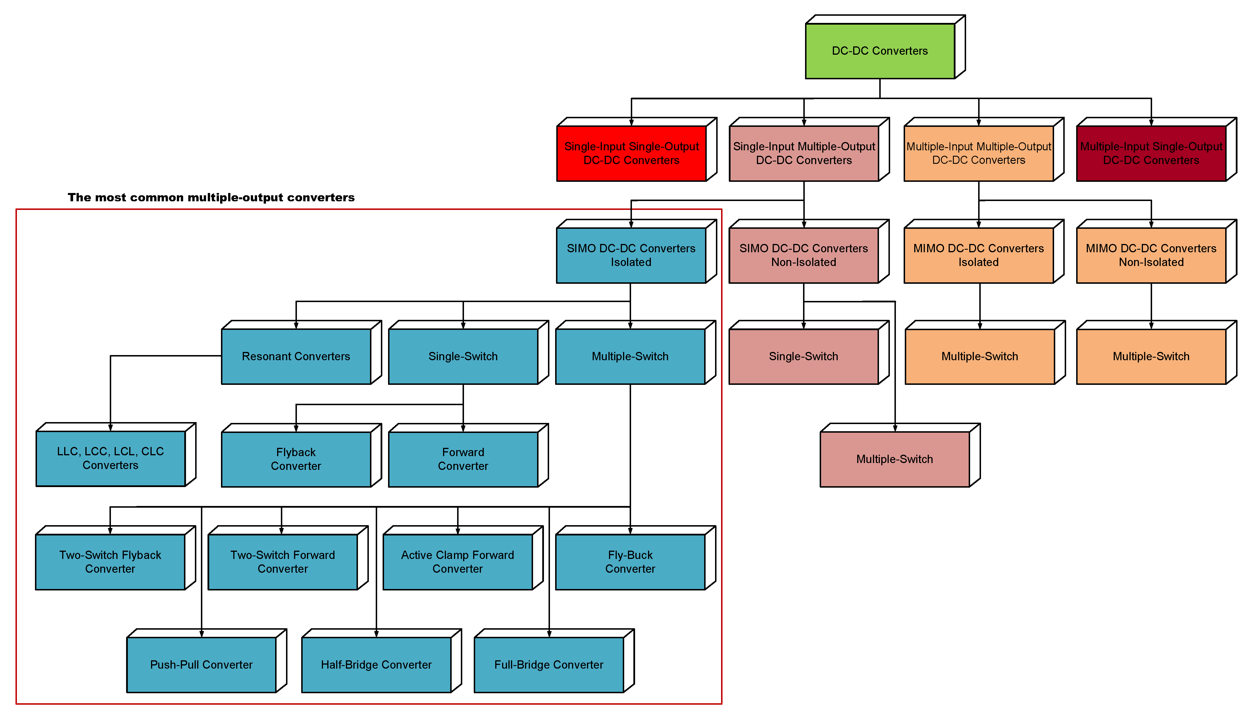
2. Multiple-Output DC–DC Converters: Topologies and Configurations
2.1. SIMO DC–DC Converters Isolated
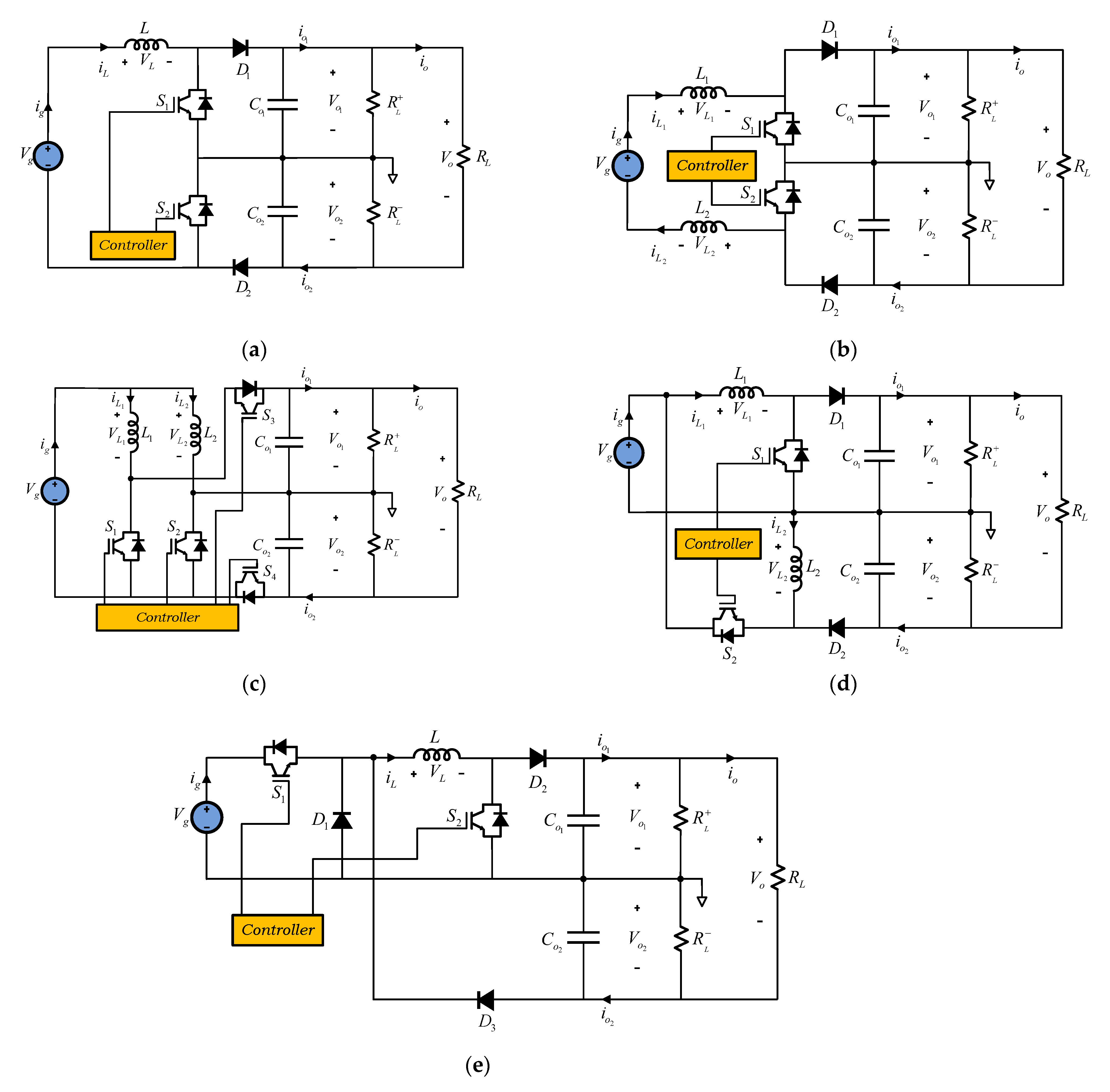
2.2. SIMO DC–DC Converters Non-Isolated
2.3. MIMO DC–DC Converters Isolated
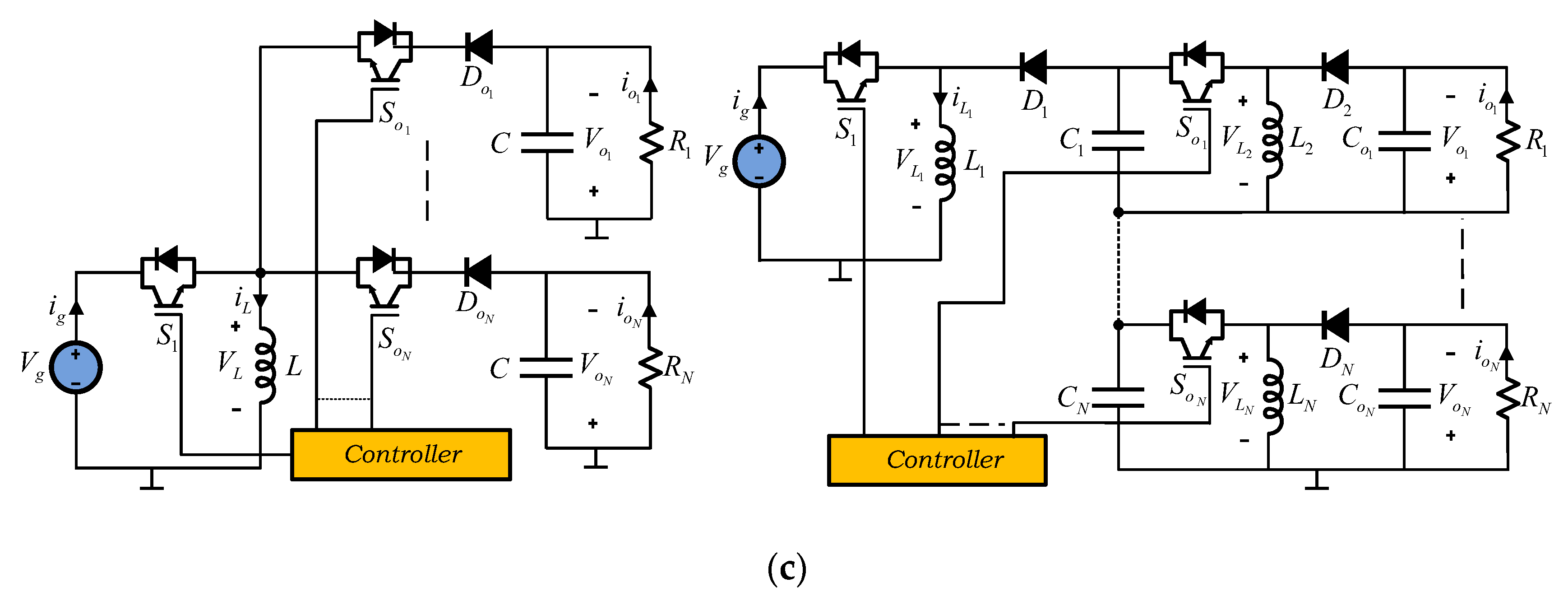
2.4. MIMO DC–DC Converters Non-Isolated
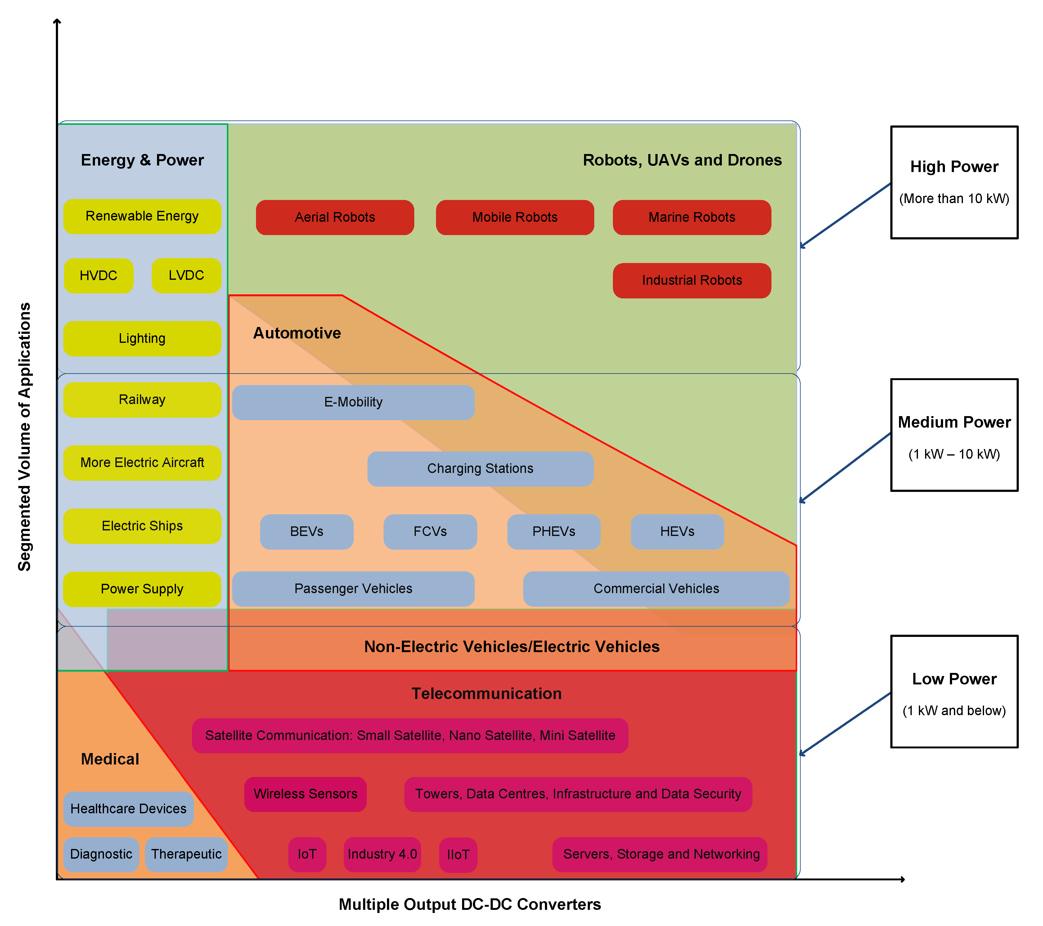
3. Multiple-Output DC–DC Converters Applications and Solutions
3.1. Converters for More Electric Aircraft
- -
- DC Voltages: 28 V, 270 V (±135 V) and 540 V (±270 V); and
- -
- AC Voltages: 230/115 V with fixed frequency of 400 Hz and 230/115 V with variable frequency (350–800 Hz).
3.2. Converters for All Electric Ships
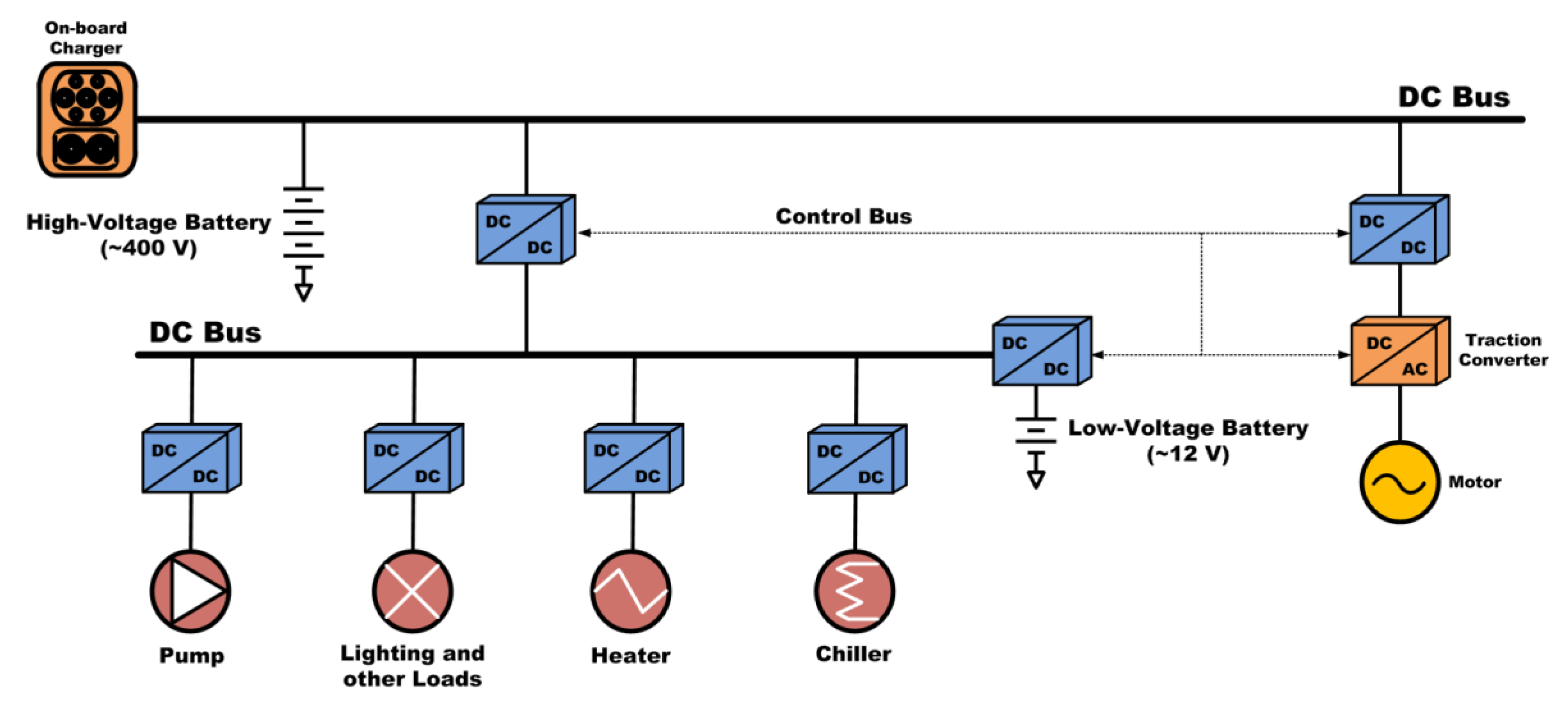
3.3. Converters for Electric/Hybrid Vehicles
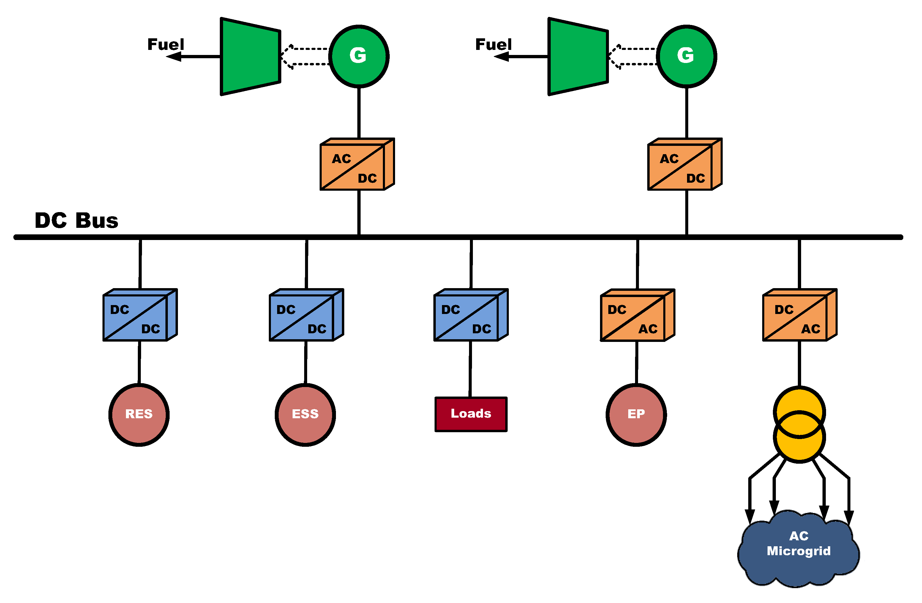
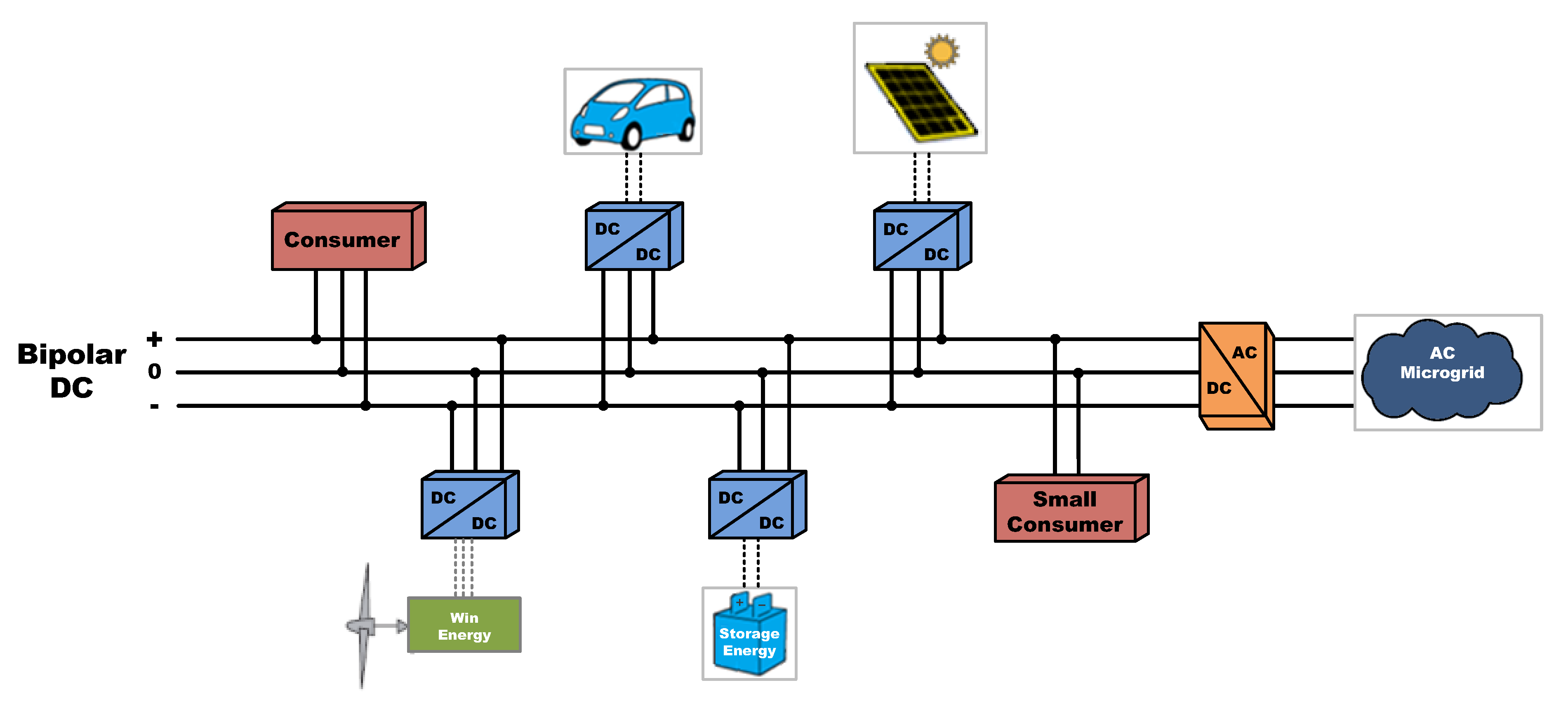
3.4. Converters for DC Microgrids
- DC networks are more efficient, they have less loss in the transmission of energy, because the effective resistance, for equal section, is lower;
- Fewer conductors are required for distribution;
- They are more stable than AC networks;
- There are no line reactances, which results in lower voltage drops;
- The frequency is zero, thus eliminating the need for a synchronization system when connecting a generation system to the grid;
- There is no transient stability problem as in AC networks; and
- No electromagnetic interference is generated.
- Currently there are no infrastructures for this type of networks; and
- The protection of DC systems is usually more complex due to the constant value of the voltage.
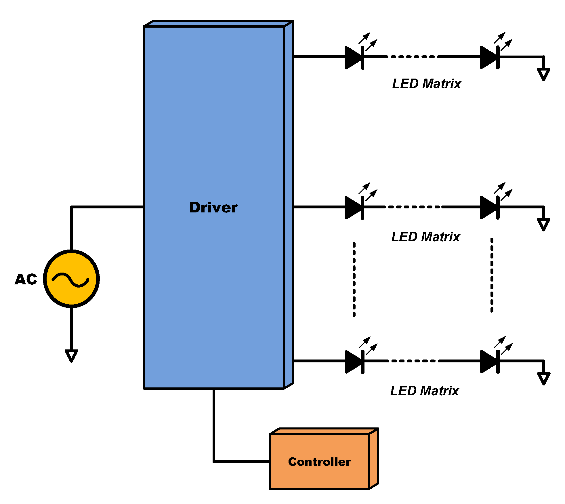
3.5. Converters for LED Ilumination Systems
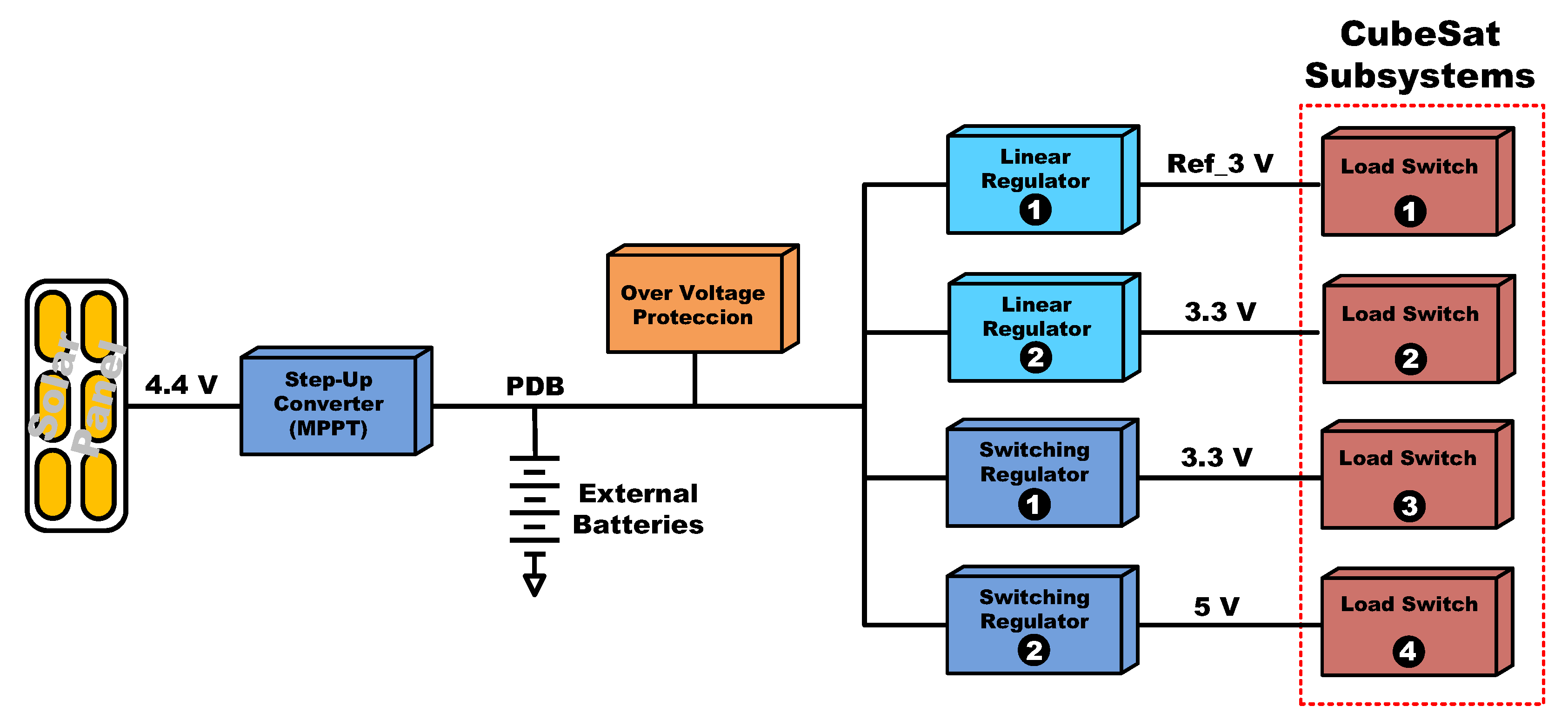
3.6. Multiple-Output DC–DC Converters for Satellite and Aerospace Applications
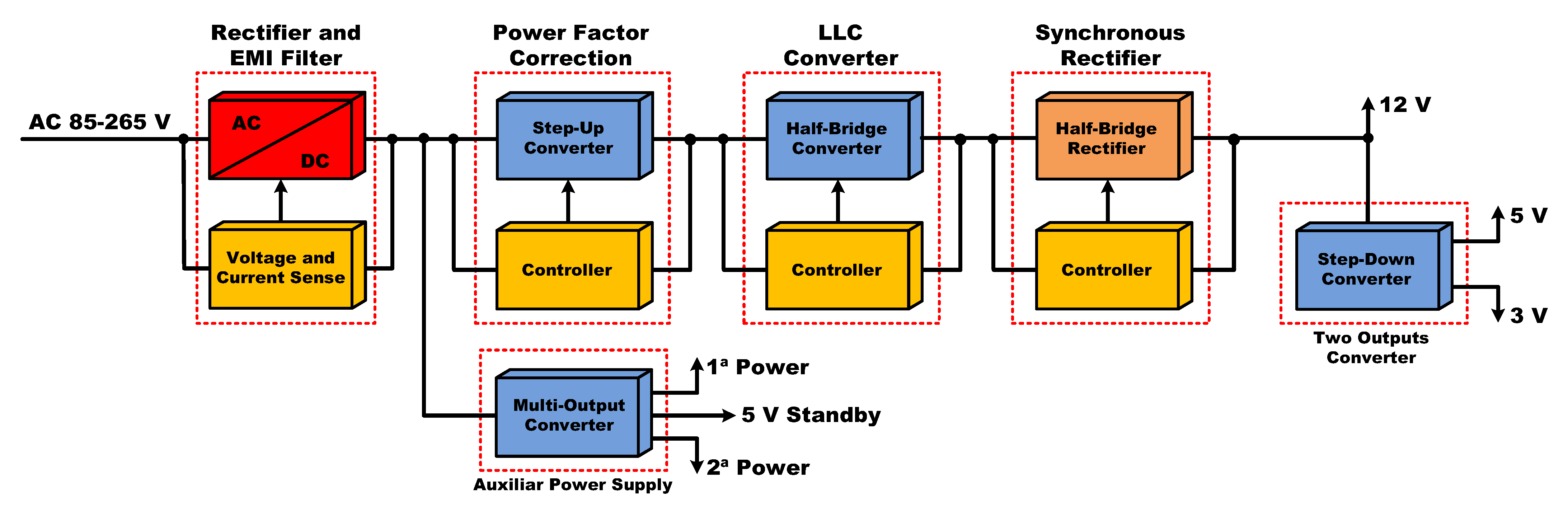
3.7. Multiple-Output DC–DC Converters in Computer Applications
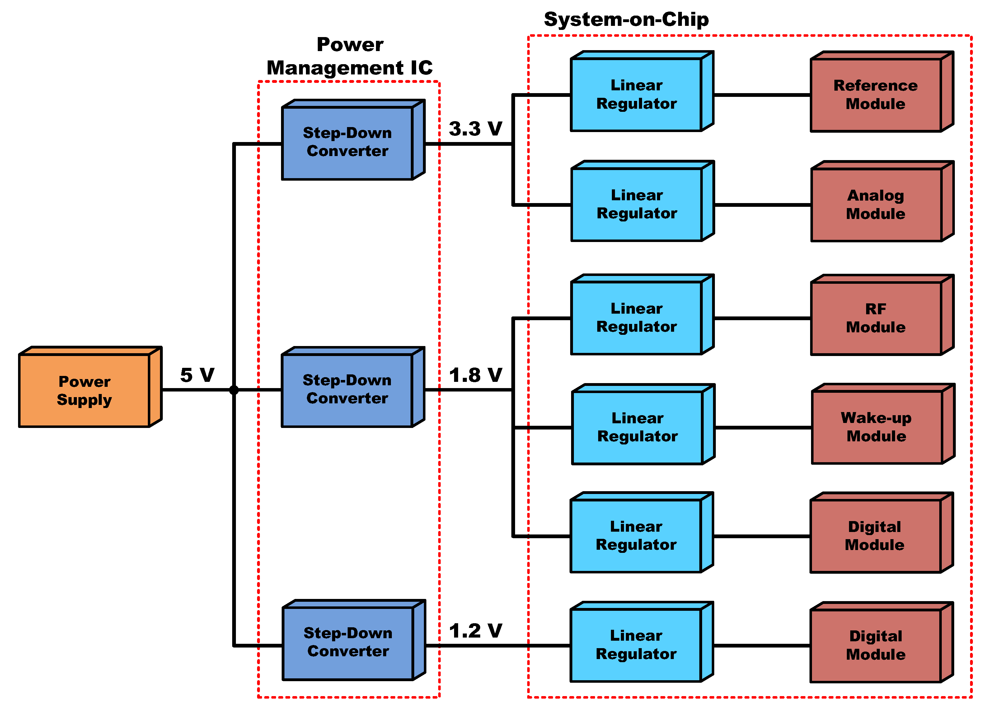
3.8. Multiple-Output DC–DC Converters in Systems-on-a-Chip (SoC)
4. Conclusions
Author Contributions
Funding
Conflicts of Interest
References
- Ballestín-Fuertes, J.; Muñoz-Cruzado-Alba, J.; Sanz-Osorio, J.F.; Laporta-Puyal, E. Role of Wide Bandgap Materials in Power Electronics for Smart Grids Applications. Electronics 2021, 10, 677. [Google Scholar] [CrossRef]
- 360 Market Updates. Available online: https://www.360marketupdates.com/ (accessed on 1 April 2022).
- Absolute Reports. Available online: https://www.absolutereports.com/ (accessed on 1 April 2022).
- Allied Market Research. Available online: https://www.alliedmarketresearch.com/ (accessed on 1 April 2022).
- DataM Intelligence. Available online: https://www.datamintelligence.com/ (accessed on 1 April 2022).
- IDTechEx Research Reports. Available online: https://www.idtechex.com/ (accessed on 1 April 2022).
- Market Research Future. Available online: https://www.marketresearchfuture.com/ (accessed on 1 April 2022).
- Market Research Reports, Business Communications Company (BCC). Available online: https://www.bccresearch.com/ (accessed on 1 April 2022).
- Omdia Research by Market. Available online: https://omdia.tech.informa.com/ (accessed on 1 April 2022).
- Report Linker. Available online: https://www.reportlinker.com/ (accessed on 1 April 2022).
- Valuates Reports. Available online: https://reports.valuates.com/ (accessed on 1 April 2022).
- eeNews Europe (Electronics Europe News). Available online: https://www.eenewseurope.com/search/node/multiple%20output%20dc-dc%20converters (accessed on 1 April 2022).
- eeNews Embedded. Available online: https://www.eenewsembedded.com/search/node/multiple%20output%20dc-dc%20converters (accessed on 1 April 2022).
- Electronics Design eNewsletter. Available online: https://www.electronicdesign.com/search?ebm_electronicdesign%5Bquery%5D=multiple%20output%20dc-dc%20converters (accessed on 1 April 2022).
- EE Times Europe Magazine. Available online: https://www.eetimes.eu/?s=multiple+output+dc-dc+converters (accessed on 1 April 2022).
- Power Electronics News. Available online: https://www.powerelectronicsnews.com/?s=multiple+output+dc-dc+converters (accessed on 1 April 2022).
- Smart2.0. Available online: https://www.smart2zero.com/search/node/multiple%20output%20dc-dc%20converters (accessed on 1 April 2022).
- DC–DC Converter Market by Vertical, Form Factor (SIP, DIP, DIN Rail, Box, Chassis Mount, Discreter, Brick), Input Voltage, Output Voltage, Output Power, Output Number, Product Type, Isolation Working Voltage and Region-Forecast to 2026. Available online: https://www.researchandmarkets.com/reports/5401801/dc-dc-converter-market-by-vertical-form-factor?utm_source=MC&utm_medium=Email&utm_code=mzrfk4g55&utm_ss=44&utm_campaign=1589384+-+dc-dc+converter+Market+-+Forecast+to+2026&utm_exec=cono266mtd (accessed on 1 April 2022).
- Global Switching Power Supply Market Size, Trends & Growth Opportunity, by Voltage Rating, by Application, by Region and Forecast to 2027. Available online: https://www.researchandmarkets.com/reports/5437868/global-switching-power-supply-market-size-trends?utm_source=MC&utm_medium=Email&utm_code=mzrj5rgey&utm_ss=44&utm_campaign=1587831+-+Global+Switching+Power+Supply+Market+Size%2c+Trends+%26+Growth+Opportunity%2c+and+Forecast+to+2027&utm_exec=cono266mtd (accessed on 1 April 2022).
- Global DC–DC Converters Market Research Report 2021, Forecast to 2026. Available online: https://www.360marketupdates.com/global-DC–DC-converters-market-19159087 (accessed on 1 April 2022).
- Rugged Power Supply Market Global Industry Analysis, Size, Share, Growth, Trends, and Forecast 2017–2025. Available online: https://www.bccresearch.com/partners/transparency/rugged-power-supply-market-global-industry-analysis-size-share-growth-trends-and-forecast.html (accessed on 1 April 2022).
- Medical Power Supply Market, Size, Share, Growth, Trends, Insight and Industry Forecast 2021–2028. Available online: https://www.datamintelligence.com/research-report/medical-power-supply-market (accessed on 1 April 2022).
- DC–DC Converter Market by Vertical, Form Factor, Input Voltage, Output Voltage, Output Power, Output Number, Product Type, Isolation Working Voltage and Region-Forecast to 2026. Available online: https://www.reportlinker.com/p04180622/Global-dc-dc-Converters-Market-by-Application-Output-Number-Input-Voltage-Output-Voltage-Output-Power-Sales-Channel-Form-Factor-Product-Type-and-Region-Forecast-to.html (accessed on 1 April 2022).
- 5G Small Cells 2021–2031: Technologies, Markets, Forecast. Available online: https://www.idtechex.com/en/research-report/5g-small-cells-2021-2031-technologies-markets-forecast/825 (accessed on 1 April 2022).
- LED Supply & Demand Market Tracker—1Q21 Analysis. Available online: https://omdia.tech.informa.com/OM018423/LED-Supply--Demand-Market-Tracker--1Q21-Analysis (accessed on 1 April 2022).
- Rugged Power Supply Market Research Report, by Component (Hardware and Software), System Type (Discrete and Integrated), Industry Vertical (Defense, Aerospace, Telecommunications, Manufacturing, Healthcare, and Transportation)—Forecast till 2027. Available online: https://www.marketresearchfuture.com/reports/rugged-power-supply-market-7150 (accessed on 1 April 2022).
- DC–DC Converter Market by Input Voltage (5–36 V, 36–75 V, 75 V and Above), Output Voltage (3.3 V, 5 V, 12 V, 15 V and Above), Mounting Style (Surface Mount and Through Hole), Application (Smartphone, Servers & Storage, EV Battery Management Unit, Railway, and Medical Equipment): Global Opportunity Analysis and Industry Forecast, 2020–2027. Available online: https://www.alliedmarketresearch.com/dc-dc-converter-market (accessed on 1 April 2022).
- Massive Multiple-Input Multiple-Output (MIMO) Market-Growth, Trends, COVID-19 Impact, and Forecasts (2021–2026). Available online: https://www.mordorintelligence.com/industry-reports/massive-multiple-input-multiple-output-mimo-market (accessed on 1 April 2022).
- Global Power Supply Unit for Servers Market Size, Manufacturers, Supply Chain, Sales Channel and Clients, 2021–2027. Available online: https://reports.valuates.com/market-reports/QYRE-Auto-15M6756/global-power-supply-unit-for-servers (accessed on 1 April 2022).
- Global Switching Power Supply Market 2021 by Manufacturers, Regions, Type and Application, Forecast to 2026. Available online: https://www.absolutereports.com/global-switching-power-supply-market-19180193 (accessed on 1 April 2022).
- Aimtec. Available online: http://www.aimtec.com/manufacture-modular-ac-dc-dc-dc-switching-power-supplies (accessed on 1 April 2022).
- CUI. Available online: https://www.cui.com/catalog/dc-dc-converters (accessed on 1 April 2022).
- Delta Electronics. Available online: https://www.deltaww.com/en-US/products/dc-dc/ALL/ (accessed on 1 April 2022).
- Flex Ltd. Available online: https://flexpowermodules.com/ (accessed on 1 April 2022).
- Infineon Technologies AG. Available online: https://www.infineon.com/cms/en/product/power/dc-dc-converters/ (accessed on 1 April 2022).
- Maxim Integrated. Available online: https://www.maximintegrated.com/en/products/power/switching-regulators.html (accessed on 1 April 2022).
- MORNSUN Power. Available online: https://www.mornsun-power.com/html/products/1986/switching-regulator.html (accessed on 1 April 2022).
- Murata Power Solutions. Available online: https://www.murata.com/products/power (accessed on 1 April 2022).
- TDK Lambda. Available online: https://www.us.lambda.tdk.com/products/dcdc-converters/ (accessed on 1 April 2022).
- Texas Instruments. Available online: https://www.ti.com/power-management/overview.html (accessed on 1 April 2022).
- Traco Power. Available online: https://www.tracopower.com/dc-dc-converters (accessed on 1 April 2022).
- Vicor Corporation. Available online: https://www.vicorpower.com/dc-dc (accessed on 1 April 2022).
- Saman, D.T.; Peng, Z.; Lu, X.; Mohsen, H. Mutual Interactions and Stability Analysis of Bipolar DC Microgrids. CSEE J. Power Energy Syst. 2019, 5, 444–453. [Google Scholar]
- Behjati, H.; Davoudi, A. A Multiple-Input Multiple Output DC–DC Converter. IEEE Trans. Ind. Appl. 2013, 49, 1464–1479. [Google Scholar]
- Tong, Y.; Shan, Z.; Jatskevich, J.; Davoudi, A. Anonisolated multiple-input multiple-output dc–dc converter for dc distribution of future energy efficient homes. In Proceedings of the IEEE 40th Annual Conference of the Industrial Electronics Society, Dallas, TX, USA, 29 October–1 November 2014; pp. 4126–4132. [Google Scholar]
- Taehyung, K.; Sangshin, K. Single pole switch leg based multi-port converter with an energy storage. Power Electron. IET 2016, 9, 1322–1330. [Google Scholar]
- Patra, P.; Patra, A.; Misra, N. A single-inductor multiple-output switcher with simultaneous Buck, Boost, and inverted out-puts. IEEE Trans. Power Electron. 2012, 27, 1936–1951. [Google Scholar] [CrossRef]
- Huang, M.H.; Chen, K.H. Single-inductor multi-output (SIMO) DC–DC converters with high light-load efficiency and mini-mized cross regulation for portable devices. IEEE J. Solid-State Circuits 2009, 44, 1099–1111. [Google Scholar] [CrossRef]
- Dhananjaya, M.; Swapnajit, P. Design and implementation of a SIMO DC–DC converter. IET Power Electron. 2019, 12, 1868–1879. [Google Scholar] [CrossRef]
- Dietrich, S.; Strache, S.; Wunderlich, R.; Heinen, S. Get the LED out: Experimental validation of a capacitor-free single-inductor, multiple-output LED driver topology. IEEE. Ind. Electron. Mag. 2015, 9, 24–35. [Google Scholar] [CrossRef]
- Nami, A.; Zare, F.; Ghosh, A.; Blaabjerg, F. Multi-output dc–dc converters based on diode clamped converters configuration: Topology and control strategy. IET Power Electron. 2010, 3, 197–208. [Google Scholar] [CrossRef] [Green Version]
- Lindiya, S.A.; Subashini, N.; Vijayarekha, K. Cross Regulation Reduced Optimal Multivariable Controller Design for Single Inductor DC–DC Converters. Energies 2019, 12, 477. [Google Scholar] [CrossRef] [Green Version]
- Abraham, D.S.; Verma, R.; Kanagaraj, L.; Raman, S.G.T.; Rajamanickam, N.; Chokkalingam, B.; Sekar, K.M.; Mihet-Popa, L. Electric Vehicles Charging Stations’ Architectures, Criteria, Power Converters, and Control Strategies in Microgrids. Electronics 2021, 10, 1895. [Google Scholar] [CrossRef]
- Bose, B. Need a Switch? IEEE Ind. Electron. Mag. 2007, 1, 30–39. [Google Scholar] [CrossRef]
- Outeiro, M.T.; Buja, G.; Czarkowski, D. Resonant Power Converters: An Overview with Multiple Elements in the Reso-nant Tank Network. IEEE Ind. Electron. Mag. 2016, 10, 21–45. [Google Scholar] [CrossRef]
- Salem, M.; Jusoh, A.; Idris, N.R.; Das, H.S.; Alhamrouni, I. Resonant power converters with respect to passive storage (LC) ele-ments and control techniques—An overview. Renew. Sustain. Energy Rev. 2018, 91, 504–520. [Google Scholar] [CrossRef]
- Li, T. Single Inductor Multiple Output Boost Regulator. U.S. Patent 6,075,295A, 13 June 2000. [Google Scholar]
- Ma, D.; Ki, W.-H.; Mok, P.K.T.; Tsui, C.-Y. Single-inductor multiple-output switching converters. Proc. IEEE PESC 2001, 1, 226–231. [Google Scholar]
- Ma, D.; Ki, W.-H.; Tsui, C.-Y. A pseudo-CCM/DCM SIMO switching converter with freewheel switching. IEEE J. Solid-State Circuits 2003, 38, 1007–1014. [Google Scholar]
- Soyka, R.; Rall, W.; Schnaubelt, J.; Sieger, P.; Kulinna, C. Process for Preparing Amino Crotonyl Compounds. U.S. Patent 20,050,085,495A1, 21 April 2005. [Google Scholar]
- Le, H.-P.; Chae, C.-S.; Lee, K.-C.; Wang, S.-W.; Cho, G.-H. A Single-Inductor Switching DC–DC Converter with Five Outputs and Ordered Power-Distributive Control. IEEE J. Solid-State Circuits 2007, 42, 2706–2714. [Google Scholar] [CrossRef]
- Seol, K.-S.; Woo, Y.-J.; Cho, G.-H.; Gho, G.-H.; Lee, J.-W. A synchronous multioutput step-up/down dc–dc converter with return current control. IEEE Trans. Circuits Syst. II Exp. Briefs 2009, 56, 210–214. [Google Scholar] [CrossRef]
- Kwon, D.; Rincon-Mora, G.A. Single-Inductor–Multiple-Output Switching DC–DC Converters. IEEE Trans. Circuits Syst. II Express Briefs 2009, 56, 614–618. [Google Scholar] [CrossRef]
- Goder, D.; Santo, H. Multiple Output Regulator with Time Sequencing. U.S. Patent 5,617,015, 1 April 1997. [Google Scholar]
- Ma, D.; Ki, W.-H.; Tsui, C.Y.; Mok, P.K.T. Single-inductor multiple-output switching converters with time-multiplexing control in discontinuous conduction mode. IEEE J. Solid-State Circuits 2003, 38, 89–100. [Google Scholar] [CrossRef]
- Li, X.L.; Dong, Z.; Tse, C.K. Complete family of two-stage singleinput multi-output configurations of interconnected power converters. IEEE Trans. Power Electron. 2020, 35, 3713–3728. [Google Scholar] [CrossRef]
- Litrán, S.P.; Durán, E.; Barroso, R.S.; Semião, J.; Ferrera, M.B. Analysis of Converters with Bipolar Output for DC Mi-crogrid. In Proceedings of the 2020 IEEE 14th International Conference on Compatibility, Power Electronics and Power Engineering (CPE-POWERENG), Setubal, Portugal, 8–10 July 2020; pp. 13–18. [Google Scholar]
- Kakigano, H.; Miura, Y.; Ise, T. Low-Voltage Bipolar-Type DC Microgrid for Super High Quality Distribution. IEEE Trans. Power Electron. 2010, 25, 3066–3075. [Google Scholar] [CrossRef]
- Zhang, M.; Jiang, Y.; Lee, F.; Jovanovic, M. Single-phase three-level boost power factor correction converter. In Proceedings of the 1995 IEEE Applied Power Electronics Conference and Exposition-APEC’95, Dallas, TX, USA, 5–9 March 1995; Volume 1, pp. 434–439. [Google Scholar]
- Haddad, K. Three level DC–DC converters as efficient interface in two stage PV power systems. In Proceedings of the 2012 IEEE Energytech, San Diego, CA, USA, 29–31 May 2012; pp. 1–6. [Google Scholar]
- Rezayi, S.; Iman-Eini, H.; Hamzeh, M.; Bacha, S.; Farzamkia, S. Dual-output DC/DC boost converter for bipolar DC microgrids. IET Renew. Power Gener. 2019, 13, 1402–1410. [Google Scholar] [CrossRef]
- Durán-Gómez, J.L.; García-Cervantes, E.; López-Flores, D.R.; Enjeti, P.N.; Palma, L. Analysis and evaluation of a series-combined connected boost and buck-boost DC–DC converter for photovoltaic application. In Proceedings of the Twenty-First Annual IEEE Applied Power Electronics Conference and Exposition, 2006, APEC’06, Dallas, TX, USA, 19–23 March 2006; pp. 19–23. [Google Scholar]
- Schoenbauer, S.; Martin-Lopez, F.R. Single Inductor Buck Boost Converter with Positive and Negative Outputs. U.S. Patent 20,100,039,080, 18 February 2010. [Google Scholar]
- Kang, H.; Cha, H. A New Nonisolated High-Voltage-Gain Boost Converter with Inherent Output Voltage Balancing. IEEE Trans. Ind. Electron. 2017, 65, 2189–2198. [Google Scholar] [CrossRef]
- Prabhakaran, P.; Agarwal, V. Novel Boost-SEPIC Type Interleaved DC–DC Converter for Mitigation of Voltage Imbalance in a Low-Voltage Bipolar DC Microgrid. IEEE Trans. Ind. Electron. 2019, 67, 6494–6504. [Google Scholar] [CrossRef]
- Kumar, P.; Singh, R.K.; Mahanty, R. Performance of MPPT-Based Minimum Phase Bipolar Converter for Photovoltaic Systems. IEEE Trans. Power Electron. 2021, 36, 5594–5609. [Google Scholar] [CrossRef]
- Zhou, X.; Wang, Y.; Wang, L.; Liu, Y.-F.; Sen, P.C. A Soft-Switching Transformerless DC−DC Converter with Single-Input Bipolar Symmetric Outputs. IEEE Trans. Power Electron. 2021, 36, 8640–8646. [Google Scholar] [CrossRef]
- Sanjeevikumar, P.; Bhaskar, M.S.; Dhond, P.; Blaabjerg, F.; Pecht, M. Non-isolated Sextuple Output Hybrid Triad Converter Configurations for High Step-Up Renewable Energy Applications. In Advances in Power Systems and Energy Management. Lecture Notes in Electrical Engineering; Springer: Singapore, 2018; Volume 436, pp. 1–12. [Google Scholar]
- Durán, E.; Litrán, S.P.; Ferrera, M.B. Configuration of DC–DC converters of one input and multiple outputs without trans-former. IET Power Electron. 2020, 13, 2658–2670. [Google Scholar] [CrossRef]
- Ferrera Prieto, M.B.; Litran, S.P.; Aranda, E.D.; Gomez, J.M.E. New Single-Input, Multiple-Output Converter Topologies: Combining Single-Switch Nonisolated DC–DC Converters for Single-Input, Multiple-Output Applications. IEEE Ind. Electron. Mag. 2016, 10, 6–20. [Google Scholar] [CrossRef]
- Tao, H.; Kotsopoulos, A.; Duarte, J.; Hendrix, M. Family of multiport bidirectional DC–DC converters. IEE Proc.-Electr. Power Appl. 2006, 153, 451–458. [Google Scholar] [CrossRef] [Green Version]
- Tao, H.; Kotsopoulos, A.; Duarte, J.; Hendrix, M. Multi-input bidirectional DC–DC converter combining DC-link and magnetic-coupling for fuel cell systems. In Proceedings of the Fourtieth IAS Annual Meeting. Conference Record of the 2005 Industry Applications Conference, Hong Kong, China, 2–6 October 2005. [Google Scholar]
- Li, X.L.; Dong, Z.; Tse, C.K.; Lu, D.D.-C. Single-Inductor Multi-Input Multi-Output DC–DC Converter with High Flexi-bility and Simple Control. IEEE Trans. Power Electron. 2020, 35, 13104–13114. [Google Scholar] [CrossRef]
- Dong, Z.; Li, Z.; Lucia, X.; Chi, L.; Tse, K.; Zhang, Z. Single-Inductor Multiple-Input Multiple-Output Con-verter With Common Ground High Scalability and No Cross-Regulation. Power Electron. IEEE Trans. 2021, 36, 6750–6760. [Google Scholar] [CrossRef]
- Chen, G.; Liu, Y.; Qing, X.; Ma, M.; Lin, Z. Principle and Topology Derivation of Single-Inductor Multi-Input Multi-Output DC–DC Converters. IEEE Trans. Ind. Electron. 2021, 68, 25–36. [Google Scholar] [CrossRef]
- Nguyen, B.L.-H.; Cha, H.; Nguyen, T.T.; Kim, H.G. Family of integrated multi-input multi-output DC–DC power converters. In Proceedings of the 2018 International Power Electronics Conference (IPEC-Niigata 2018-ECCE Asia), Niigata, Japan, 20–24 May 2018; pp. 3134–3139. [Google Scholar]
- Roboam, X.; Sareni, B.; De Andrade, A. More Electricity in the Air: Toward Optimized Electrical Networks Embedded in More-Electrical Aircraft. IEEE Ind. Electron. Mag. 2012, 6, 6–17. [Google Scholar] [CrossRef] [Green Version]
- Ansell, P.J.; Haran, K.S. Electrified Airplanes: A Path to Zero-Emission Air Travel. IEEE Electrif. Mag. 2020, 8, 18–26. [Google Scholar] [CrossRef]
- Madonna, V.; Giangrande, P.; Galea, M. Electrical Power Generation in Aircraft: Review, Challenges, and Opportunities. IEEE Trans. Transp. Electrif. 2018, 4, 646–659. [Google Scholar] [CrossRef]
- Wheeler, P.; Bozhko, S. The More Electric Aircraft: Technology and challenges. IEEE Electrif. Mag. 2014, 2, 6–12. [Google Scholar] [CrossRef]
- Brelje, B.J.; Martins, J.R. Electric, hybrid, and turboelectric fixed-wing aircraft: A review of concepts, models, and design approaches. Prog. Aerosp. Sci. 2019, 104, 1–19. [Google Scholar] [CrossRef]
- Buticchi, G.; Bozhko, S.; Liserre, M.; Wheeler, P.; Al-Haddad, K. On-Board Microgrids for the More Electric Aircraft—Technology Review. IEEE Trans. Ind. Electron. 2019, 66, 5588–5599. [Google Scholar] [CrossRef] [Green Version]
- Buticchi, G.; Costa, L.; Liserre, M. Improving System Efficiency for the More Electric Aircraft: A Look at dc\/dc Converters for the Avionic Onboard dc Microgrid. IEEE Ind. Electron. Mag. 2017, 11, 26–36. [Google Scholar] [CrossRef]
- Rojas-Duenas, G.; Riba, J.-R.; Moreno-Eguilaz, M. A Deep Learning-Based Modeling of a 270 V-to-28 V DC–DC Converter Used in More Electric Aircrafts. IEEE Trans. Power Electron. 2021, 37, 509–518. [Google Scholar] [CrossRef]
- Gu, C.; Yan, H.; Yang, J.; Sala, G.; De Gaetano, D.; Wang, X.; Galassini, A.; Degano, M.; Zhang, X.; Buticchi, G. A Multiport Power Conversion System for the More Electric Aircraft. IEEE Trans. Transp. Electrif. 2020, 6, 1707–1720. [Google Scholar] [CrossRef]
- Yang, J.; Buticchi, G.; Gu, C.; Gunter, S.; Zhang, H.; Wheeler, P. A Generalized Input Impedance Model of Multiple Active Bridge Converter. IEEE Trans. Transp. Electrif. 2020, 6, 1695–1706. [Google Scholar] [CrossRef]
- Buticchi, G.; Costa, L.F.; Liserre, M. Multi-port DC/DC converter for the electrical power distribution system of the more electric aircraft. Math. Comput. Simul. 2018, 158, 387–402. [Google Scholar] [CrossRef]
- Khersonsky, Y.; Hingorani, N.; Peterson, K.L. IEEE Electric Ship Technologies initiative. In Proceedings of the 2009 Record of Conference Papers-Industry Applications Society 56th Annual Petruleum and Chemical Industry Conference, Anaheim, CA, USA, 14–16 September 2009; pp. 1–10. [Google Scholar] [CrossRef]
- Mukund, R.P. Shipboard Electrical Power Systems; CRC Press: Boca Raton, FL, USA, 2012. [Google Scholar]
- Kim, K.; Park, K.; Roh, G.; Chun, K. DC-grid system for ships: A study of benefits and technical considerations. J. Int. Marit. Saf. Environ. Aff. Shipp. 2018, 2, 1–12. [Google Scholar] [CrossRef] [Green Version]
- Thongam, J.S.; Tarbouchi, M.; Okou, A.F.; Bouchard, D.; Beguenane, R. Trends in naval ship propulsion drive motor technology. In Proceedings of the 2013 IEEE Electrical Power & Energy Conference, Halifax, NS, Canada, 21–23 August 2013; pp. 1–5. [Google Scholar] [CrossRef]
- Su, C.-L.; Lin, K.-L.; Chen, C.-J. Power Flow and Generator-Converter Schemes Studies in Ship MVDC Distribution Systems. IEEE Trans. Ind. Appl. 2015, 52, 50–59. [Google Scholar] [CrossRef]
- Skjong, E.; Volden, R.; Rodskar, E.; Molinas, M.; Johansen, T.A.; Cunningham, J. Past, Present, and Future Challenges of the Marine Vessel’s Electrical Power System. IEEE Trans. Transp. Electrif. 2016, 2, 522–537. [Google Scholar] [CrossRef] [Green Version]
- Dai, J.; Nam, S.W.; Pande, M.; Esmaeili, G. Medium-Voltage Current-Source Converter Drives for Marine Propulsion System Using a Dual-Winding Synchronous Machine. IEEE Trans. Ind. Appl. 2014, 50, 3971–3976. [Google Scholar] [CrossRef]
- Moradisizkoohi, H.; Elsayad, N.; Mohammed, O.A. A Bipolar DC–DC Converter with Wide Voltage-Gain Range for Energy Storage Integration in Ship Power Systems. In Proceedings of the 2019 IEEE Electric Ship Technologies Symposium (ESTS), Washington, DC, USA, 14–16 August 2019; pp. 511–517. [Google Scholar]
- Steinsland, V.; Kristensen, L.M.; Arghandeh, R.; Zhang, S. Design of Modular Multilevel Converters for the Shipnet in Medium Voltage DC All-Electric Ships. In Proceedings of the 2020 IEEE 21st Workshop on Control and Modeling for Power Electronics (COMPEL), Aalborg, Denmark, 9–12 November 2020; pp. 1–8. [Google Scholar]
- Bazzi, A.M.; Liu, Y.; Fay, D.S. Electric Machines and Energy Storage: Over a Century of Technologies in Electric and Hybrid Electric Vehicles. IEEE Electrif. Mag. 2018, 6, 49–53. [Google Scholar] [CrossRef]
- Ehsani, M.; Singh, K.V.; Bansal, H.O.; Mehrjardi, R.T. State of the Art and Trends in Electric and Hybrid Electric Vehicles. Proc. IEEE 2021, 109, 967–984. [Google Scholar] [CrossRef]
- Saponara, S.; Lee, C.H.; Wang, N.X.; Kirtley, J.L. Electric Drives and Power Chargers: Recent Solutions to Improve Performance and Energy Efficiency for Hybrid and Fully Electric Vehicles. IEEE Veh. Technol. Mag. 2020, 15, 73–83. [Google Scholar] [CrossRef]
- Zhou, X.; Sheng, B.; Liu, W.; Chen, Y.; Wang, L.; Liu, Y.-F.; Sen, P.C. A High-Efficiency High-Power-Density On-Board Low-Voltage DC–DC Converter for Electric Vehicles Application. IEEE Trans. Power Electron. 2021, 36, 12781–12794. [Google Scholar] [CrossRef]
- Elsayad, N.; Moradisizkoohi, H.; Mohammed, O.A. A Single-Switch Transformerless DC--DC Converter with Universal Input Voltage for Fuel Cell Vehicles: Analysis and Design. IEEE Trans. Veh. Technol. 2019, 68, 4537–4549. [Google Scholar] [CrossRef]
- Janabi, A.; Wang, B. Switched-Capacitor Voltage Boost Converter for Electric and Hybrid Electric Vehicle Drives. IEEE Trans. Power Electron. 2019, 35, 5615–5624. [Google Scholar] [CrossRef]
- Elsayad, N.; Moradisizkoohi, H.; Mohammed, O.A. A New Hybrid Structure of a Bidirectional DC–DC Converter with High Conversion Ratios for Electric Vehicles. IEEE Trans. Veh. Technol. 2019, 69, 194–206. [Google Scholar] [CrossRef]
- Zhang, Y.; Gao, Y.; Zhou, L.; Sumner, M. A Switched-Capacitor Bidirectional DC–DC Converter with Wide Voltage Gain Range for Electric Vehicles With Hybrid Energy Sources. IEEE Trans. Power Electron. 2018, 33, 9459–9469. [Google Scholar] [CrossRef]
- Gu, C.; Zheng, Z.; Xu, L.; Wang, K.; Li, Y. Modeling and Control of a Multiport Power Electronic Transformer (PET) for Electric Traction Applications. IEEE Trans. Power Electron. 2016, 31, 915–927. [Google Scholar] [CrossRef]
- Ahrabi, R.R.; Ardi, H.; Elmi, M.; Ajami, A. A Novel Step-Up Multiinput DC–DC Converter for Hybrid Electric Vehicles Application. IEEE Trans. Power Electron. 2017, 32, 3549–3561. [Google Scholar] [CrossRef]
- Saponara, S.; Tisserand, P.; Chassard, P.; My-Ton, D. DC/DC converter integrated architecture for 48V supplies in micro/mild hybrid vehicle electrical engine control module. In Proceedings of the 2016 IEEE 16th International Conference on Environment and Electrical Engineering (EEEIC), Florence, Italy, 7–10 June 2016; pp. 1–5. [Google Scholar]
- Rivera, S.; Kouro, S.; Vazquez, S.; Goetz, S.M.; Lizana, R.; Romero-Cadaval, E. Electric Vehicle Charging Infrastructure: From Grid to Battery. IEEE Ind. Electron. Mag. 2021, 15, 37–51. [Google Scholar] [CrossRef]
- Khaligh, A.; D’Antonio, M. Global Trends in High-Power On-Board Chargers for Electric Vehicles. IEEE Trans. Veh. Technol. 2019, 68, 3306–3324. [Google Scholar] [CrossRef]
- Mehta, R.; Srinivasan, D.; Khambadkone, A.M.; Yang, J.; Trivedi, A. Smart Charging Strategies for Optimal Integration of Plug-In Electric Vehicles Within Existing Distribution System Infrastructure. IEEE Trans. Smart Grid 2018, 9, 299–312. [Google Scholar] [CrossRef]
- Shahidehpour, M. Role of smart microgrid in a perfect power system. In Proceedings of the IEEE PES General Meeting, Minneapolis, MN, USA, 25–29 July 2010; p. 1. [Google Scholar]
- Kroposki, B.; Lasseter, R.; Ise, T.; Morozumi, S.; Papathanassiou, S.; Hatziargyriou, N. Making microgrids work. IEEE Power Energy Mag. 2008, 6, 40–53. [Google Scholar] [CrossRef]
- Wang, H.; Li, W.; Yue, Y.; Zhao, H. Distributed Economic Control for AC/DC Hybrid Microgrid. Electronics 2021, 11, 13. [Google Scholar] [CrossRef]
- Eghtedarpour, N.; Farjah, E. Power Control and Management in a Hybrid AC/DC Microgrid. IEEE Trans. Smart Grid 2014, 5, 1494–1505. [Google Scholar] [CrossRef]
- Patterson, B.T. DC, Come Home: DC Microgrids and the Birth of the “Enernet”. IEEE Power Energy Mag. 2012, 10, 60–69. [Google Scholar] [CrossRef]
- Lotfi, H.; Khodaei, A. AC versus DC Microgrid Planning. IEEE Trans. Smart Grid 2017, 8, 296–304. [Google Scholar] [CrossRef]
- Salonen, P.; Kaipia, T.; Nuutinen, P.; Peltoniemi, P.; Partanen, J. An LVDC Distribution System Concept. In Proceedings of the Nordic Workshop on Power and Industrial Electronics, Espoo, Finland, 9–11 June 2008. [Google Scholar]
- Lv, J.; Wang, X.; Wang, G.; Song, Y. Research on Control Strategy of Isolated DC Microgrid Based on SOC of Energy Storage System. Electronics 2021, 10, 834. [Google Scholar] [CrossRef]
- Prabhakaran, P.; Agarwal, V. Novel Four-Port DC–DC Converter for Interfacing Solar PV–Fuel Cell Hybrid Sources With Low-Voltage Bipolar DC Microgrids. IEEE J. Emerg. Sel. Top. Power Electron. 2020, 8, 1330–1340. [Google Scholar] [CrossRef]
- Tian, Q.; Zhou, G.; Leng, M.; Xu, G.; Fan, X. A Nonisolated Symmetric Bipolar Output Four-Port Converter Interfacing PV-Battery System. IEEE Trans. Power Electron. 2020, 35, 11731–11744. [Google Scholar] [CrossRef]
- Kolahian, P.; Tarzamni, H.; Nikafrooz, A.; Hamzeh, M. Multi-port DC–DC converter for bipolar medium voltage DC micro-grid applications. IET Power Electron. 2019, 12, 1841–1849. [Google Scholar] [CrossRef]
- Lee, J.-O.; Kim, Y.-S.; Moon, S.-I. Current Injection Power Flow Analysis and Optimal Generation Dispatch for Bipolar DC Microgrids. IEEE Trans. Smart Grid 2021, 12, 1918–1928. [Google Scholar] [CrossRef]
- Alonso, J.M. LED Lighting and Drivers; Amazon KDP: Seattle, WA, USA, 2019. [Google Scholar]
- Wang, Y.; Alonso, J.M.; Ruan, X. A Review of LED Drivers and Related Technologies. IEEE Trans. Ind. Electron. 2017, 64, 5754–5765. [Google Scholar] [CrossRef]
- Almeida, P.; Camponogara, D.; Costa, M.D.; Braga, H.A.C.; Alonso, J.M. Matching LED and Driver Life Spans: A Review of Different Techniques. IEEE Ind. Electron. Mag. 2015, 9, 36–47. [Google Scholar] [CrossRef]
- Cheng, C.-A.; Chang, C.-H.; Chung, T.-Y.; Yang, F.-L. Design and Implementation of a Single-Stage Driver for Supplying an LED Street-Lighting Module with Power Factor Corrections. IEEE Trans. Power Electron. 2014, 30, 956–966. [Google Scholar] [CrossRef]
- Poorali, B.; Adib, E. Analysis of the Integrated SEPIC-Flyback Converter as a Single-Stage Single-Switch Power-Factor-Correction LED Driver. IEEE Trans. Ind. Electron. 2016, 63, 3562–3570. [Google Scholar] [CrossRef]
- Zhang, F.; Ni, J.; Yu, Y. High Power Factor AC–DC LED Driver with Film Capacitors. IEEE Trans. Power Electron. 2012, 28, 4831–4840. [Google Scholar] [CrossRef]
- Wang, Y.; Guan, Y.; Xu, D.; Wang, W. A CLCL Resonant DC/DC Converter for Two-Stage LED Driver System. IEEE Trans. Ind. Electron. 2016, 63, 2883–2891. [Google Scholar] [CrossRef]
- Camponogara, D.; Vargas, D.R.; Costa, M.D.; Alonso, J.M.; Garcia, J.; Marchesan, T. Capacitance Reduction With An Optimized Converter Connection Applied to LED Drivers. IEEE Trans. Ind. Electron. 2014, 62, 184–192. [Google Scholar] [CrossRef]
- Wang, Y.; Huang, J.; Wang, W.; Xu, D. A Single-Stage Single-Switch LED Driver Based on Class-E Converter. IEEE Trans. Ind. Appl. 2016, 52, 2618–2626. [Google Scholar] [CrossRef]
- Pouladi, F.; Farzanehfard, H.; Adib, E. Battery operated soft switching resonant buck–boost LED driver with single magnetic element. IEEE Trans. Power Electron 2019, 34, 2704–2711. [Google Scholar] [CrossRef]
- Mukherjee, S.; Yousefzadeh, V.; Sepahvand, A.; Doshi, M.; Maksimovic, D. A Two-Stage Automotive LED Driver with Multiple Outputs. IEEE Trans. Power Electron. 2021, 36, 14175–14186. [Google Scholar] [CrossRef]
- Pinto, R.A.; Alonso, J.M.; Perdigao, M.S.; Da Silva, M.F.; Prado, R.N.D. A New Technique to Equalize Branch Currents in Multiarray LED Lamps Based on Variable Inductors. IEEE Trans. Ind. Appl. 2015, 52, 521–530. [Google Scholar] [CrossRef]
- He, Q.; Luo, Q.; Huang, J.; Cao, C.; Sun, P. Analysis and design of modular open-loop LED driver with multi-channel output currents. IET Power Electron. 2019, 12, 1721–1729. [Google Scholar] [CrossRef]
- He, Q.; Luo, Q.; Wei, Y.; Sun, P. A Variable Inductor Controlled Single-Stage AC/DC Converter for Modular Multi-Channel LED Driver. IEEE Trans. Energy Convers. 2021, 36, 2912–2923. [Google Scholar] [CrossRef]
- Zhang, Y.; Rong, G.; Qu, S.; Song, Q.; Tang, X.; Zhang, Y. A High-Power LED Driver Based on Single Inductor-Multiple Output DC–DC Converter With High Dimming Frequency and Wide Dimming Range. IEEE Trans. Power Electron. 2020, 35, 8501–8511. [Google Scholar] [CrossRef]
- Lee, J.; Kim, E.; Shin, K.G. Design and Management of Satellite Power Systems. In Proceedings of the 2013 IEEE 34th Real-Time Systems Symposium, Vancouver, BC, Canada, 3–6 December 2013; pp. 97–106. [Google Scholar]
- Ali, A.; Mughal, M.R.; Ali, H.; Reyneri, L. Innovative power management, attitude determination and control tile for CubeSat standard NanoSatellites. Acta Astronaut. 2014, 96, 116–127. [Google Scholar] [CrossRef]
- SMPS POWER SUPPLY for ATX COMPUTERS. Available online: https://www.smpspowersupply.com/power-supply.html (accessed on 1 April 2022).
- Liu, C. Gain Top-Notch Efficiency for Your Desktop PSU. Industrial-Technical Articles-TI E2E Support Forums. 30 October 2017. Available online: https://e2e.ti.com/blogs_/b/industrial_strength/posts/gain-top-notch-efficiency-for-your-desktop-psu (accessed on 1 April 2022).
- Dasgupta, A.; Potta, M.; Vaishaka, N.R.; Meghana, D.R.; Kendaganna, S.S. SoC Power Management Unit for IoI Applications. Sci. Technol. Dev. 2021, 10, 169. [Google Scholar]
- Semiao, J.; Duran, E.; Litrán, S.P.; Ferrera, M.B. Multiple-Output Switched-Capacitor DC-DC Combination Converters for IoT Applications. In Proceedings of the 2020 IEEE 14th International Conference on Compatibility, Power Electronics and Power Engineering (CPE-POWERENG), Setúbal, Portugal, 8–10 July 2020; Volume 1, pp. 143–148. [Google Scholar]
- Semião, J.; Cabral, R.; Santos, M.B.; Teixeira, I.C.; Teixeira, J.P. Performance Sensor for Reliable Operation. In Proceedings of the UAHCI: 12th International Conference on Universal Access in Human-Computer Interaction, Integrated in the 20th HCII, Las Vegas, NV, USA, 15–20 July 2018; pp. 347–365. [Google Scholar]
- Semião, R.J.; Cabral, H.; Cavalaria, M.; Santos, I.C.; Teixeira, J.; Teixeira, P. Ultra-Low-Power Strategy for Reliable IoE Na-noscale Integrated Circuits. In Harnessing the Internet of Everything (IoE) for Accelerated Innovation Opportunities; IGI Global: Hershey, PA, USA, 2019. [Google Scholar]


| Converter | CCM | DCM |
|---|---|---|
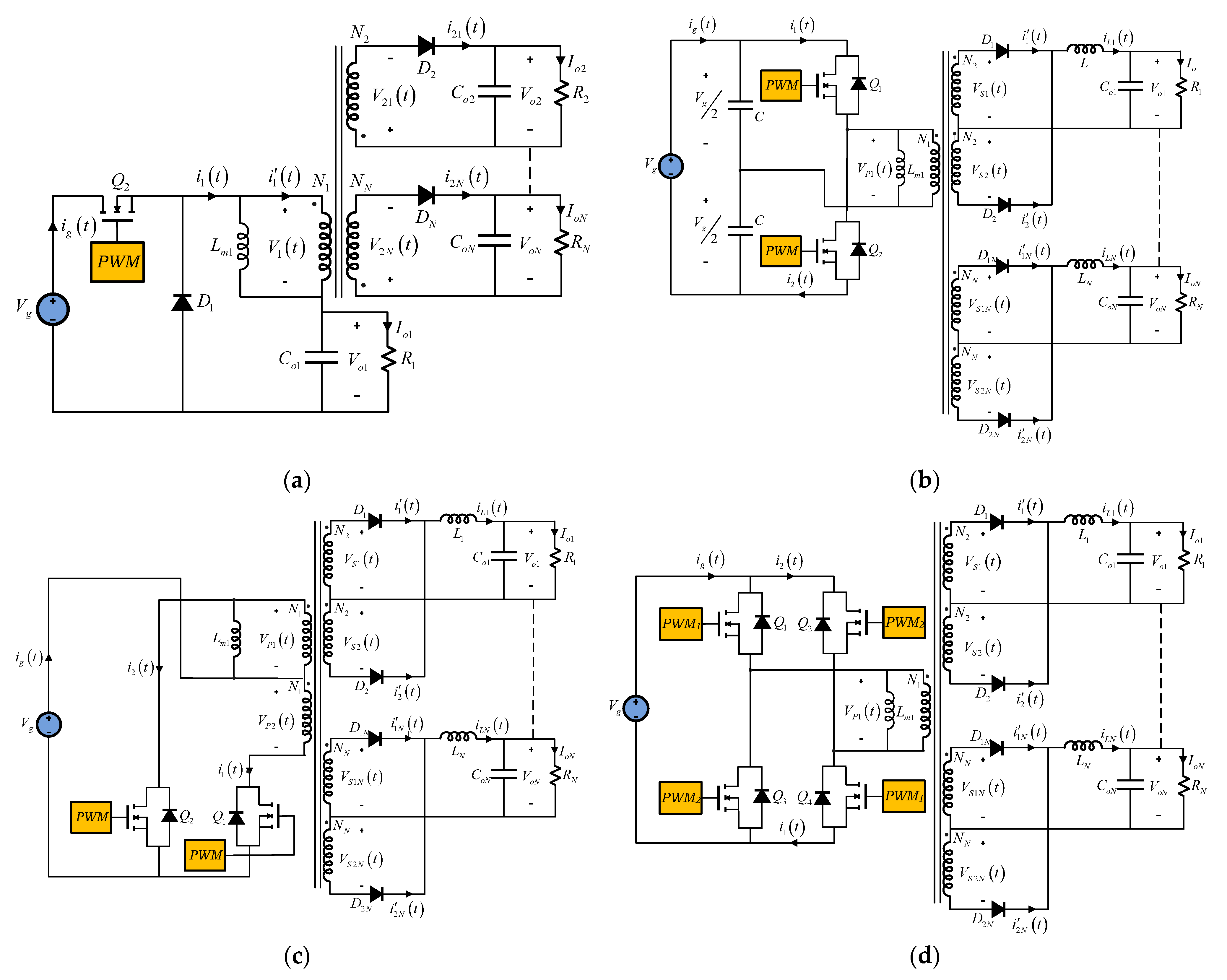
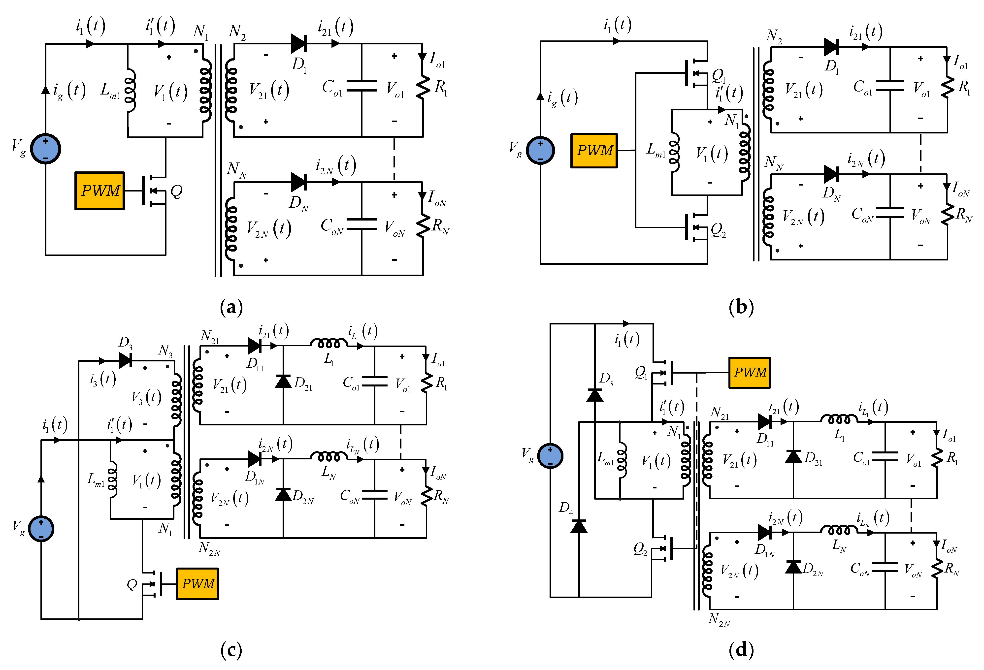
| Flyback Converter (Figure 3a,b) | ||
| Isolated Buck Converter (Figure 5a) | ||
| Forward Converter (Figure 3c,d) | ||
| Active Clamp Forward Converter (Figure 4a) | ||
| Push–Pull Converter (Figure 5c) | ||
| Half-Bridge Converter (Figure 5b) | ||
| Full-Bridge Converter (Figure 5d) | ||
| Buck–Boost-Derived Isolated Converters (Figure 4b–d) | ||
| Nomenclature: Vg: Source voltage N: Winding turn number D: Duty cycle | R: Load resistance L: Inductance Ts: Switching period | |
| Type Converter | Number Switches | Number Components | Voltage Stress | Transformer Utility | Floating Switches | Input/Output Feature |
|---|---|---|---|---|---|---|
| Single-Switch Flyback | Low | Low | High | Moderate | No | Discontinuous input current Discontinuous output currents |
| Two-Switch Flyback | Medium | Low | Medium | Moderate | Yes | Discontinuous input current Discontinuous output currents |
| Single-Switch Forward | Low | Medium | High | Moderate | No | Discontinuous input current Continuous output currents |
| Two-Switch Forward | Medium | Medium | Medium | Moderate | Yes | Discontinuous input current Continuous output currents |
| Active Clamp Forward | Medium | High | Medium | Moderate | Yes | Discontinuous input current Continuous output currents |
| Isolated Zeta | Low | Medium | High | Moderate | No | Discontinuous input current Continuous output currents |
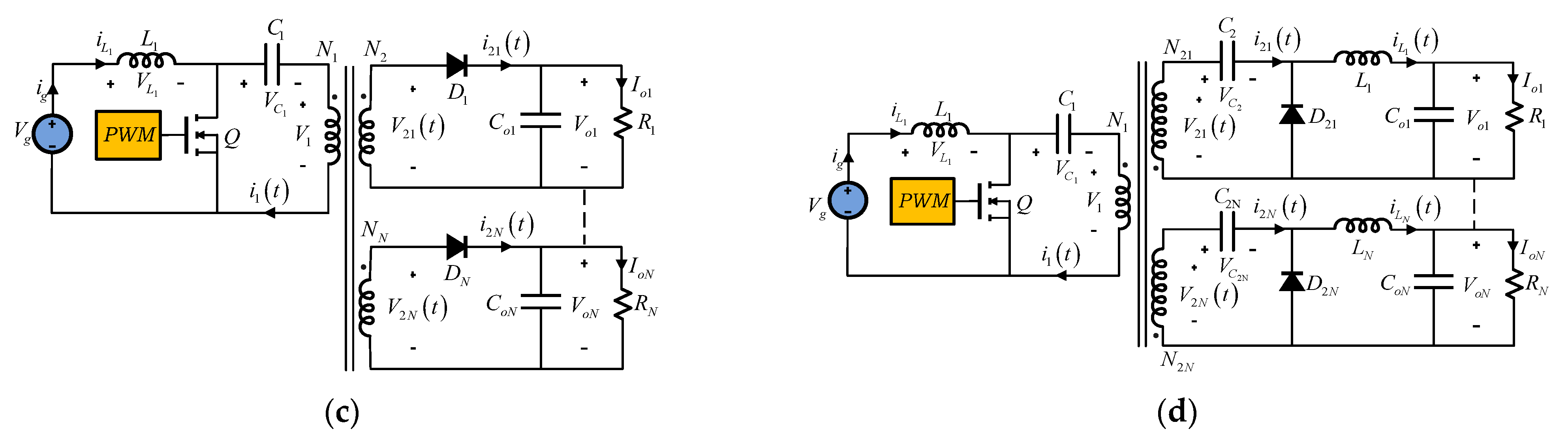
| Isolated SEPIC | Low | Medium | High | Moderate | No | Continuous input current Discontinuous output currents |
| Isolated Ćuk | Low | Medium | High | Moderate | No | Continuous input current Continuous output currents |
| Isolated Buck (Fly–Buck) | Low | Low | Medium | Moderate | Yes | Discontinuous input current Discontinuous output currents |
| Half-Bridge | Medium | Medium | Medium | Good | Yes | Continuous input current Continuous output currents |
| Push–Pull | Medium | High | Medium | Good | No | Continuous input current Continuous output currents |
| Full-Bridge | High | High | Low | Good | Yes | Continuous input current Continuous output currents |
| Converter | Output Voltages | |
|---|---|---|
| LLC Resonant DC–DC Converter (Figure 6a) | ||
| LCC Resonant DC–DC Converter (Figure 6b) | ||
| Nomenclature: Vg: Source voltage N: Winding turn number D: Duty cycle R: Load resistance | L: Inductance fs: Switching frequency fR: Resonance frequency Q = Quality factor | |
| Type Converter | Number Switches | Number Components | Voltage Stress | Transformer Utility | Floating Switches | Input/Output Feature |
|---|---|---|---|---|---|---|
| LLC Resonant | Medium | Medium | Medium | Good | Yes | Discontinuous input current Continuous output currents |
| LCC Resonant | Medium | High | Medium | Good | Yes | Discontinuous input current Continuous output currents |
| Converter | CCM | DCM |
|---|---|---|
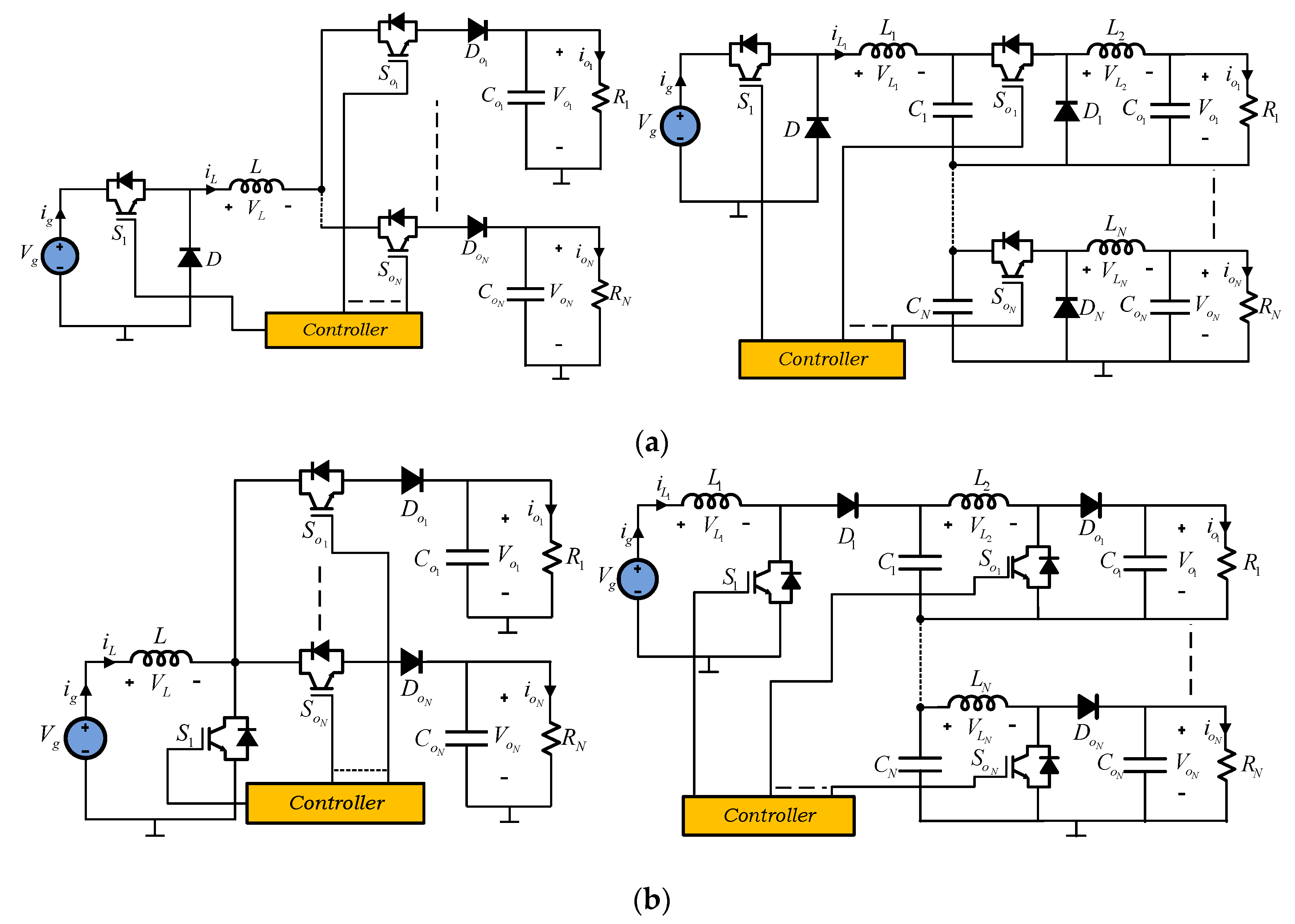
| Boost Converter (Figure 8a) | ||
| Buck–Boost Converter (Figure 8e) | ||
| Nomenclature: Vg: Source voltage Ig: Source curren D: Duty cycle | R: Load resistance L: Inductance Ts: Switching period |
| Type Converter | Number Switches | Number Components | Voltage Stress | Floating Switches | Input/Output Feature |
|---|---|---|---|---|---|
| SIMO Buck | Medium | Medium | High | Yes | Discontinuous input current Discontinuous output currents |
| SIMO Boost | Medium | Medium | High | Yes | Continuous input current Discontinuous output currents |
| SIMO Buck–Boost | Medium | Medium | High | Yes | Discontinuous input current Discontinuous output currents |
| Three-level Single- inductor Boost | Medium | Low | Medium | Yes | Continuous input current Discontinuous output currents |
| Three-level Two- inductors Boost | Medium | Low | Medium | Yes | Continuous input current Discontinuous output currents |
| Dual-output DC–DC Boost | Medium | Low | Medium | No | Continuous input current Discontinuous output currents |
| Series-combined Boost and Buck–Boost | Medium | Low | Medium | Yes | Continuous input current Discontinuous output currents |
| Single-inductor Buck–Boost | Medium | Medium | Medium | Yes | Discontinuous input current Discontinuous output currents |
| Boost–Ćuk combination | Low | Low | High | No | Continuous input current Discontinuous/Continuous output currents |
| Boost–SEPIC combination | Low | Low | High | No | Continuous input current Discontinuous output currents |
| Buck–Boost–Zeta combination | Low | Low | High | Yes | Discontinuous input current Discontinuous/Continuous output currents |
| SEPIC–Ćuk combination | Low | Low | High | No | Continuous input current Discontinuous/Continuous output currents |
| Three-output-type converter for six loads | Low | Medium | High | No | Continuous input current Discontinuous/Continuous output currents |
| Type Converter | Number Switches | Number Components | Voltage Stress | Transformer Utility | Floating Switches | Input/Output Feature |
|---|---|---|---|---|---|---|
| Boost parallel | High | High | Medium | Good | Yes | Continuous input currents Continuous output currents |
| Boost ports | High | High | Medium | Good | Yes | Continuous input currents Continuous output currents |
| Half-Bridge | High | Medium | Medium | Good | Yes | Continuous input currents Continuous output currents |
| Boost–Half Bridge | High | High | Medium | Good | Yes | Continuous input currents Continuous output currents |
| Type Converter | Number Switches | Number Components | Voltage Stress | Floating Switches | Input/Output Feature |
|---|---|---|---|---|---|
| Series outputs | Medium | Low | High | Yes | Discontinuous input/ output currents |
| Series inputs and series outputs | Medium | High | High | Yes | Discontinuous input/ output currents |
Publisher’s Note: MDPI stays neutral with regard to jurisdictional claims in published maps and institutional affiliations. |
© 2022 by the authors. Licensee MDPI, Basel, Switzerland. This article is an open access article distributed under the terms and conditions of the Creative Commons Attribution (CC BY) license (https://creativecommons.org/licenses/by/4.0/).
Share and Cite
Litrán, S.P.; Durán, E.; Semião, J.; Díaz-Martín, C. Multiple-Output DC–DC Converters: Applications and Solutions. Electronics 2022, 11, 1258. https://doi.org/10.3390/electronics11081258
Litrán SP, Durán E, Semião J, Díaz-Martín C. Multiple-Output DC–DC Converters: Applications and Solutions. Electronics. 2022; 11(8):1258. https://doi.org/10.3390/electronics11081258
Chicago/Turabian StyleLitrán, Salvador P., Eladio Durán, Jorge Semião, and Cristian Díaz-Martín. 2022. "Multiple-Output DC–DC Converters: Applications and Solutions" Electronics 11, no. 8: 1258. https://doi.org/10.3390/electronics11081258
APA StyleLitrán, S. P., Durán, E., Semião, J., & Díaz-Martín, C. (2022). Multiple-Output DC–DC Converters: Applications and Solutions. Electronics, 11(8), 1258. https://doi.org/10.3390/electronics11081258