
M-Emu: A Platform for Multicast Emulation

Abstract
1. Introduction
- 1.
- M-Emu presents a Service-Forwarding Architecture, which enables the data plane to process packet scheduling tasks and to deploy arbitrary complex multicast protocols and algorithms.
- 2.
- Based on the Service-Forwarding Architecture, M-Emu integrates a Multicast-Emulation Framework. The Multicast-Emulation Framework has a complete multicast tree construction and maintenance mechanism, which can reduce the workload emulations.
- 3.
- We deploy statistical tools for common multicast performance metrics.
- 4.
- The effectiveness and efficiency of M-Emu is analyzed theoretically and experimentally.
2. Related Work
3. Implementation
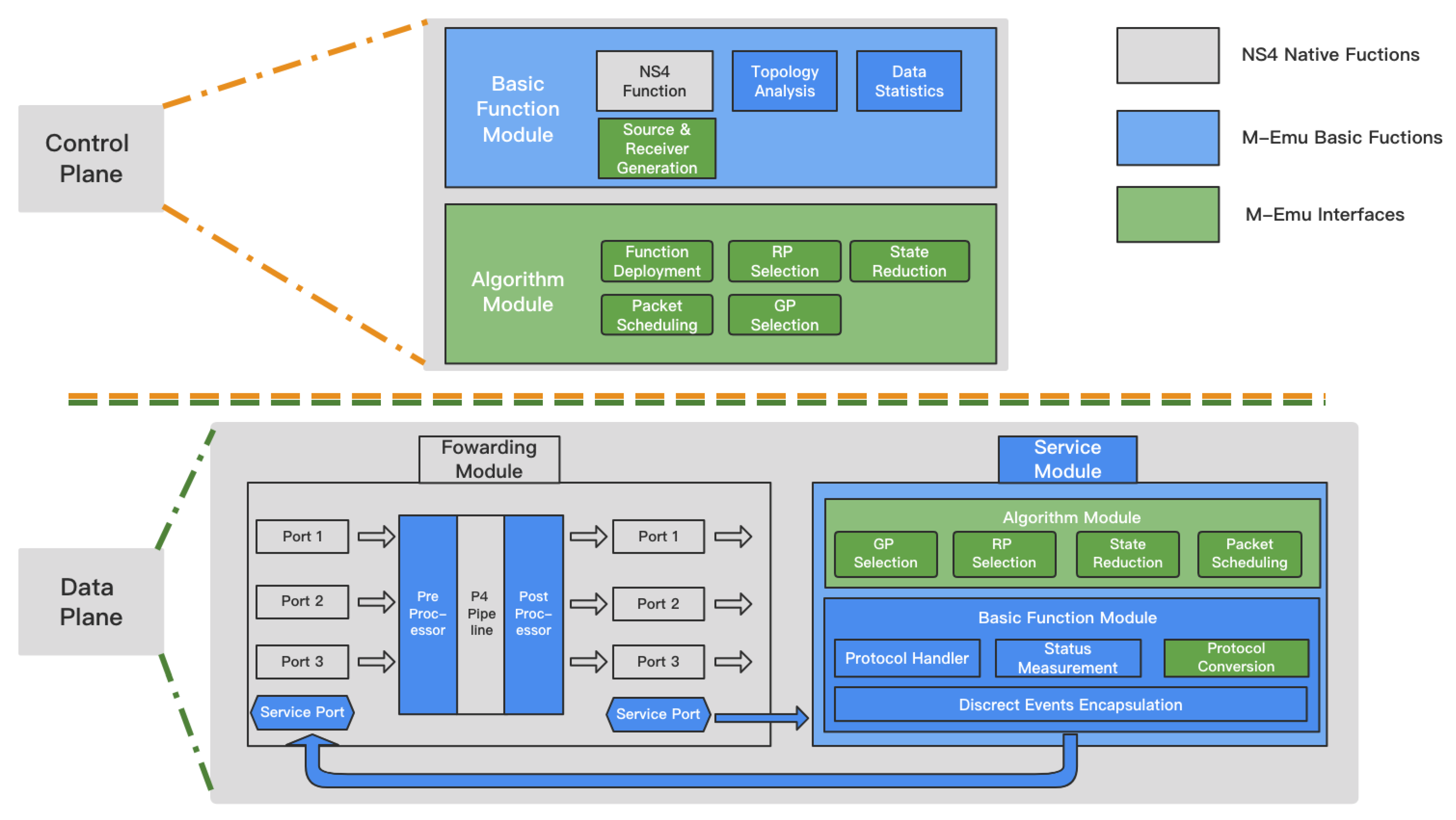
3.1. Service-Forwarding Architecture
3.1.1. Control Plane
3.1.2. Data Plane
3.1.3. Analysis of Service-Forwarding Architecture
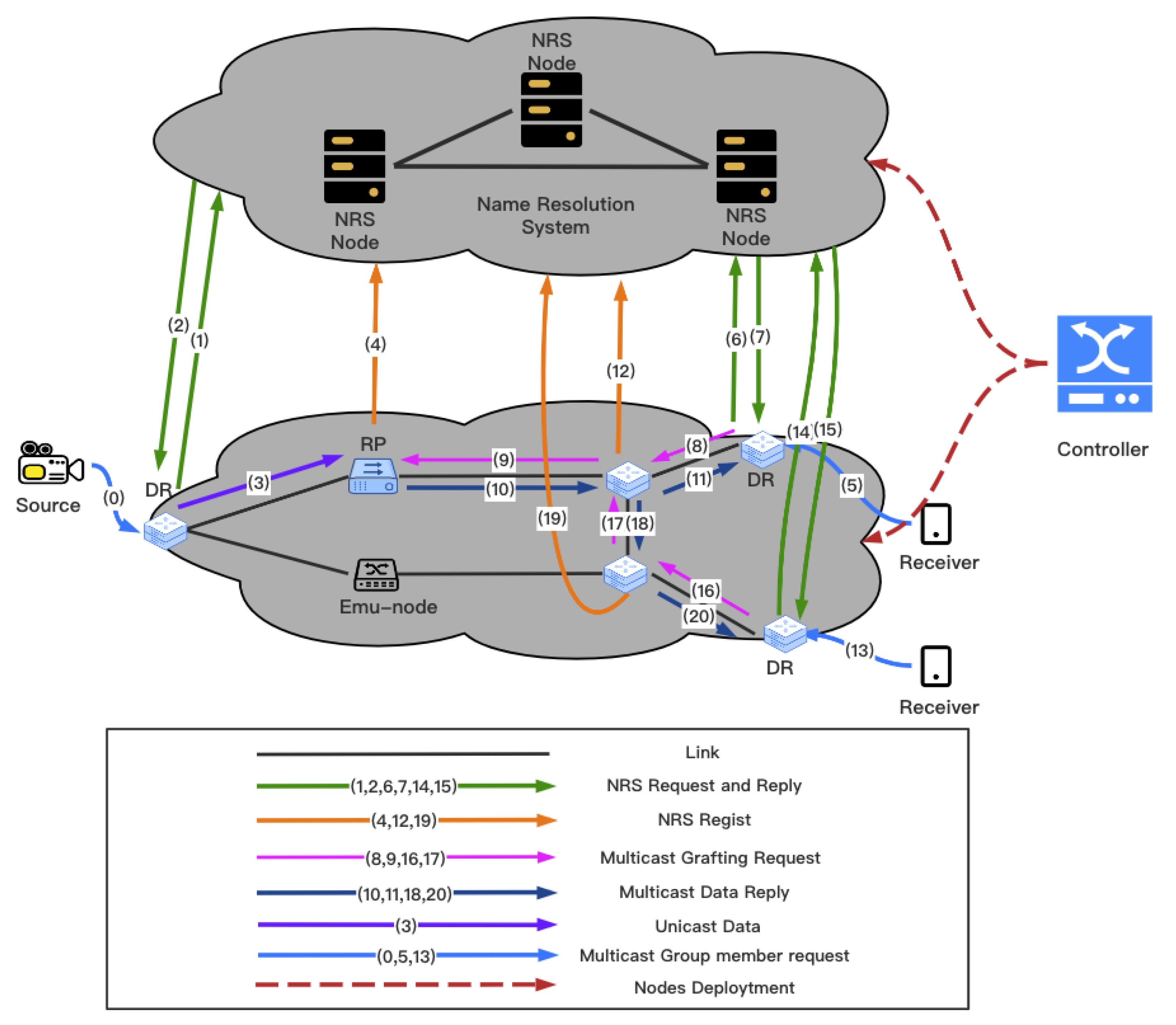
3.2. Multicast-Emulation Framework
3.2.1. Introduction to Key Elements
3.2.2. Construction and Maintenance Mechanism of Multicast Tree
3.3. Statistics Tools
- (1)
- The MFT load. The MFT load of each node is obtained by calculating the MFT size of each node.
- (2)
- The Link load. With the link ID as the index, the amount of data passing through the link throughout the experiment can be obtained. In addition, the load changes of links in different time periods can be analyzed according to time stamps.
- (3)
- The Multicast tree cost. With the multicast ID as the index, all the links that the multicast tree passes through can be obtained, and then the cost of the entire multicast tree can be obtained.
- (4)
- The End-to-end delay. According to the multicast ID and packet type, the time when the DR sends data and the time when the DR receives data can be counted, and then the end-to-end transmission delay can be calculated.
3.4. Statement of Main Interfaces
- Statistical tools. These are used to calculate the network status and evaluate the advantages and disadvantages of each algorithm.
4. Validation
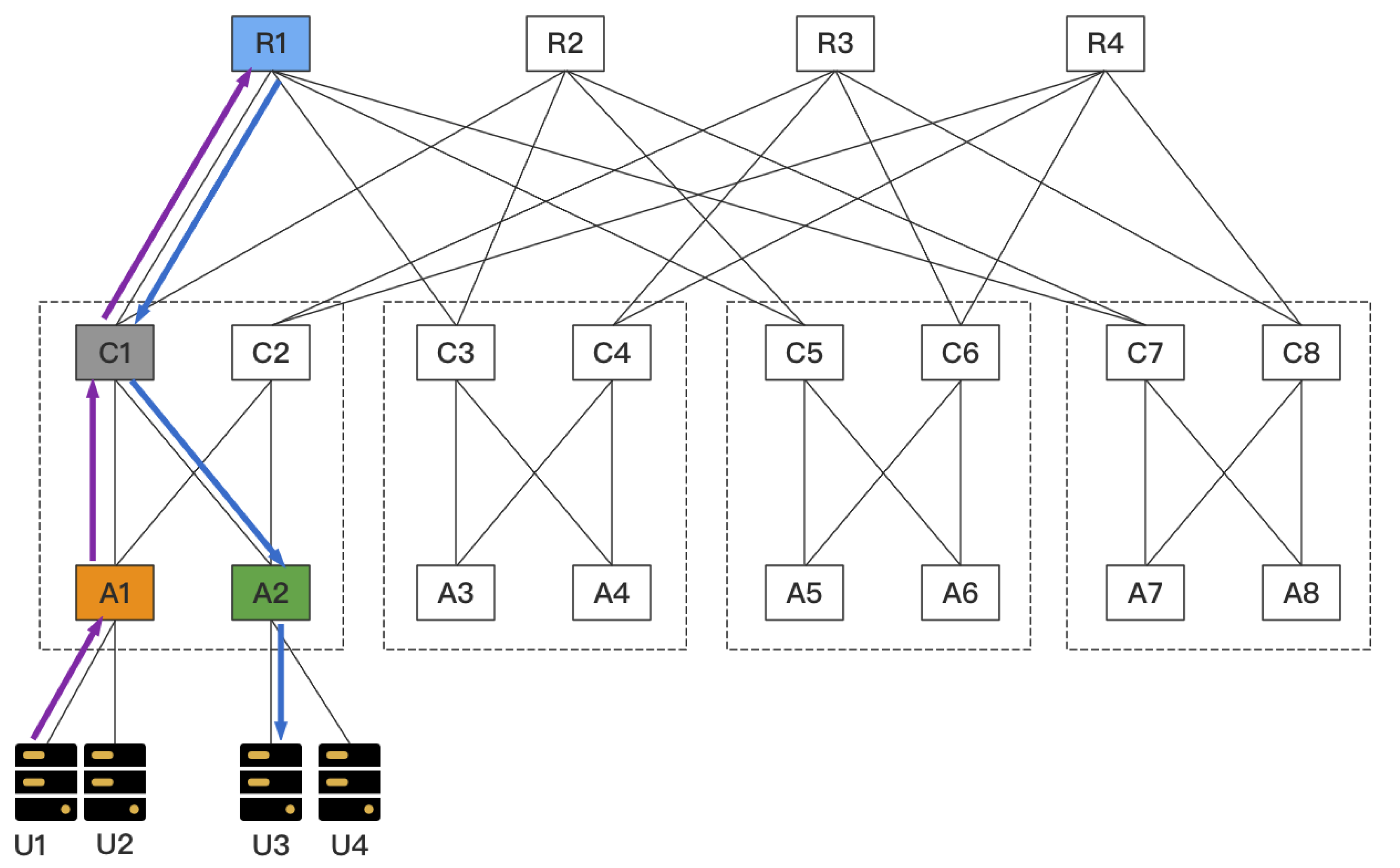
4.1. Case Study
- void SetDR(
- std::map < std::string, Ptr > nodeMap,
- const NodeContainer nodes,
- NodeContainer* senderDR,
- NodeContainer* receiverDR)
- void SetRP(
- std::Map < std::string, Ptr > nodeMap,
- const NodeContainer Nodes,
- NodeContainer * cRPs)
- uint32_t GetRootNode(
- const NodeContainer cRPs,
- uint8_t * buffer, void* info)
- uint32_t GetGraftNode(
- uint8_t * buffer, void* info)
- bool StateReduction(
- uint8_t* buffer, void *info)
- MFT load: R1, C1, A1 and A2 all need to maintain the multicast forwarding state for this multicast group, and thus their MFT load is +1.
- Link Load: Links R1-C1, C1-A1 and C1-A2 all need to forward the multicast stream, and their load is 100 Kb/s.
- Multicast tree cost: The multicast tree forwards 100 bits of data through three links. Therefore, the Multicast tree cost is 300 bits.
- End-to-end delay: According to the time stamp of each data packet, the time of sending data from A1 to A2 is 5 ms.
4.2. Emulation Performance
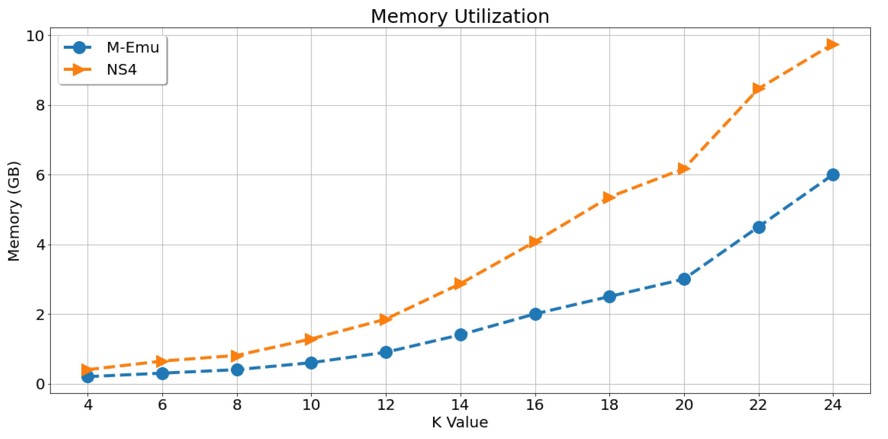
- Memory Consumption. This metric indicates the memory size required by the emulation platform to process a certain number of multicast flows.
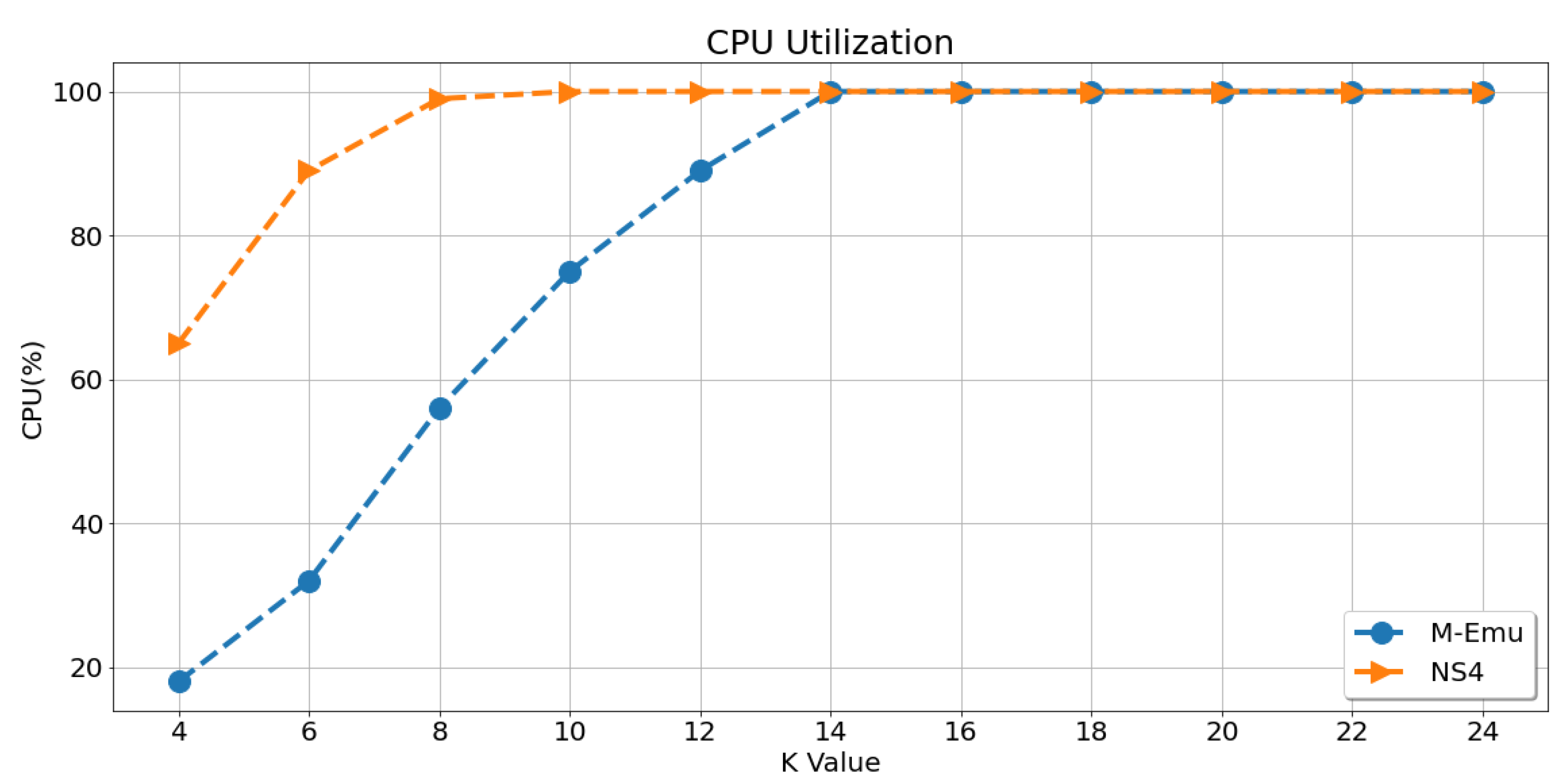
- CPU utilization. This metric indicates the CPU utilization by the emulation platform to process a certain number of multicast flows.
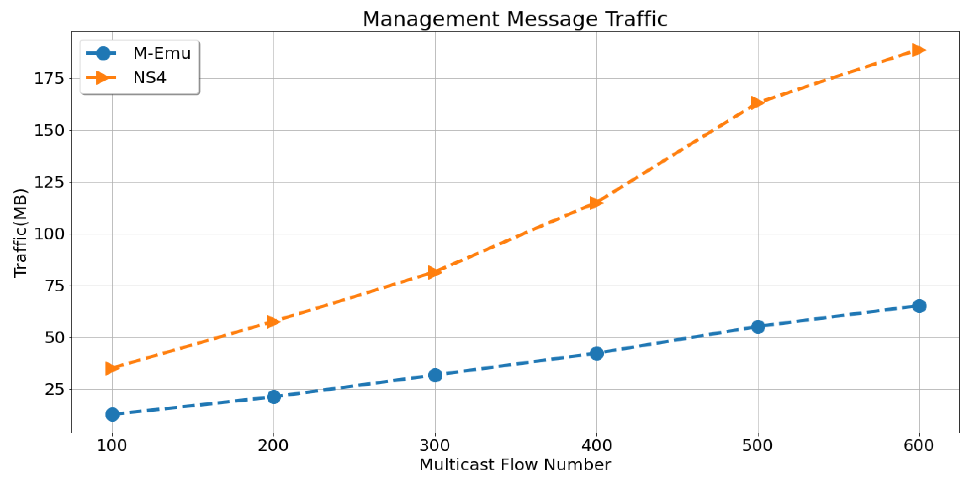
- Traffic of Management Message. This metric indicates the traffic of various management messages when the same number of multicast flows (1000) are completed.
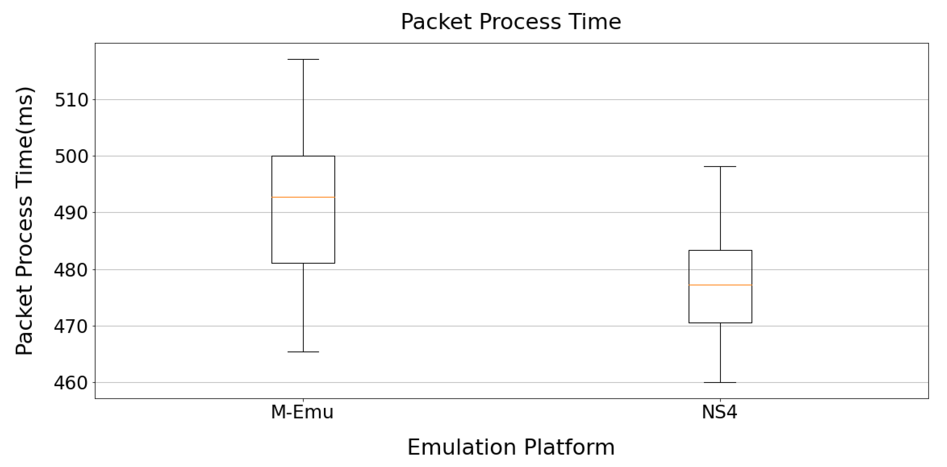
- Packet Process time of Emu-Node. This metric indicates the time required for the emulation platform to interact with the real network.
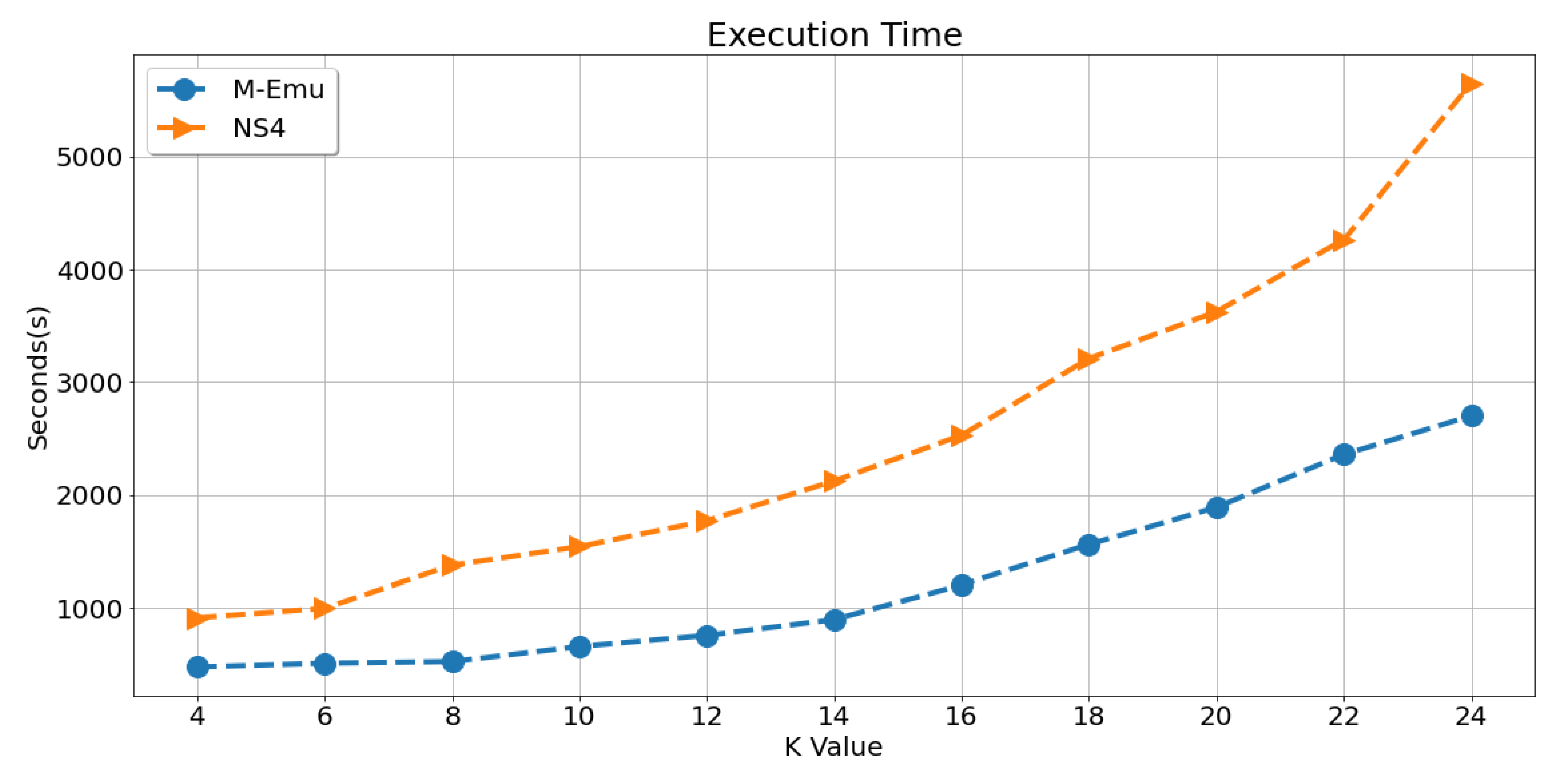
- Execution Time. This metric indicates the time required by the emulation platform to process a certain number of multicast flows.
4.2.1. Memory Consumption
4.2.2. CPU Utilization
4.2.3. Traffic of Management message
4.2.4. Packet Process Time of Emu-Node
4.2.5. Execution Time
4.2.6. Code Complexity
5. Conclusions
Author Contributions
Funding
Institutional Review Board Statement
Informed Consent Statement
Data Availability Statement
Acknowledgments
Conflicts of Interest
References
- Paul, P.; Raghavan, S.V. Survey of multicast routing algorithms and protocols. In Proceedings of the Fifteenth International Conference on Computer Communication (ICCC 2002), Mumbai, India, 12–14 August 2002; pp. 902–926. [Google Scholar]
- Roca, V.; Costa, L.; Vida, R.; Dracinschi, A.; Fdida, S. A Survey of Multicast Technologies; Work in Progress; Chicago, IL, USA. 2000. Available online: https://home.nr.no/~abie/Papers/sota_mcast.pdf (accessed on 1 March 2022).
- AlSaeed, Z.; Ahmad, I.; Hussain, I. Multicasting in software defined networks: A comprehensive survey. J. Netw. Comput. Appl. 2018, 104, 61–77. [Google Scholar] [CrossRef]
- Islam, S.; Muslim, N.; Atwood, J.W. A survey on multicasting in software-defined networking. IEEE Commun. Surv. Tutor. 2017, 20, 355–387. [Google Scholar] [CrossRef]
- Oliveira, C.A.; Pardalos, P.M. A survey of combinatorial optimization problems in multicast routing. Comput. Oper. Res. 2005, 32, 1953–1981. [Google Scholar] [CrossRef]
- Fan, C.; Bi, J.; Zhou, Y.; Zhang, C.; Yu, H. Ns4: A p4-driven network simulator. In Proceedings of the SIGCOMM Posters and Demos, Los Angeles, CA, USA, 22–24 August 2017; pp. 105–107. [Google Scholar]
- Tortelli, M.; Rossi, D.; Boggia, G.; Grieco, L.A. Icn software tools: Survey and cross-comparison. Simul. Model. Pract. Theory 2016, 63, 23–46. [Google Scholar] [CrossRef]
- Tortelli, M.; Rossi, D.; Boggia, G.; Grieco, L.A. Cross-comparison of icn software tools. In Proceedings of the ACM Conference on Information-Centric Networking (ICN’14), Paris, France, 24–26 September 2014. [Google Scholar]
- Bosshart, P.; Daly, D.; Gibb, G.; Izzard, M.; McKeown, N.; Rexford, J.; Schlesinger, C.; Talayco, D.; Vahdat, A.; Varghese, G.; et al. P4: Programming protocol-independent packet processors. ACM SIGCOMM Comput. Commun. Rev. 2014, 44, 87–95. [Google Scholar] [CrossRef]
- Kanaya, T.; Nakao, A.; Yamamoto, S.; Yamauchi, H.; Nirasawa, S.; Oguchi, M.; Yamaguchi, S. Intelligent application switch supporting tcp. In Proceedings of the 2018 IEEE 7th International Conference on Cloud Networking (CloudNet), Tokyo, Japan, 22–24 October 2018; pp. 1–4. [Google Scholar]
- Li, S.; Hu, D.; Fang, W.; Ma, S.; Chen, C.; Huang, H.; Zhu, Z. Protocol oblivious forwarding (pof): Software-defined networking with enhanced programmability. IEEE Netw. 2017, 31, 58–66. [Google Scholar] [CrossRef]
- Nirasawa, S.; Nakao, A.; Yamamoto, S.; Hara, M.; Oguchi, M.; Yamaguchi, S. Application switch using dpn for improving tcp based data center applications. In Proceedings of the 2017 IFIP/IEEE Symposium on Integrated Network and Service Management (IM), Lisbon, Portugal, 8–12 May 2017; pp. 995–998. [Google Scholar]
- Kreutz, D.; Ramos, F.M.; Verissimo, P.E.; Rothenberg, C.E.; Azodolmolky, S.; Uhlig, S. Software-defined networking: A comprehensive survey. Proc. IEEE 2014, 103, 14–76. [Google Scholar] [CrossRef]
- Chen, S.; Gunluk, O.; Yener, B. The multicast packing problem. IEEE/ACM Trans. Netw. 2000, 8, 311–318. [Google Scholar] [CrossRef]
- Wang, J.; Cheng, G.; You, J.; Sun, P. Seanet: Architecture and technologies of an on-site, elastic, autonomous network. J. Netw. New Media 2020, 6, 1–8. [Google Scholar]
- KhadirKumar, N.; Bharathi, A. Real time energy efficient data aggregation and scheduling scheme for wsn using atl. Comput. Commun. 2020, 151, 202–207. [Google Scholar]
- Lee, D.-L.; Youn, C.-H.; Jeong, S.-J. RP reselection scheme for real-time applications in delay-constrained multicast networks. In Proceedings of the 2002 IEEE International Conference on Communications. Conference Proceedings. ICC 2002 (Cat. No. 02CH37333), New York, NY, USA, 28 April–2 May 2002; Volume 2, pp. 1290–1294. [Google Scholar]
- Wang, H.; Meng, X.; Zhang, M.; Li, Y. Tabu search algorithm for rp selection in PIM-SM multicast routing. Comput. Commun. 2010, 33, 35–42. [Google Scholar] [CrossRef][Green Version]
- Che, F.; Lloyd, E.L. The complexity of rp selection in multicast channelization. In Proceedings of the MILCOM 2009—2009 IEEE Military Communications Conference, Boston, MA, USA, 18–21 October 2009; pp. 1–7. [Google Scholar]
- Biersack, E.; Nonnenmacher, J. Wave: A new multicast routing algorithm for static and dynamic multicast groups. In International Workshop on Network and Operating Systems Support for Digital Audio and Video; Springer: Berlin/Heidelberg, Germany, 1995; pp. 228–239. [Google Scholar]
- Wang, C.-F.; Liang, C.-T.; Jan, R.-H. Heuristic algorithms for packing of multiple-group multicasting. Comput. Oper. Res. 2002, 29, 905–924. [Google Scholar] [CrossRef]
- Guan, J.; Gao, S.; Li, X.; Zhou, H.; Zhang, H. The analysis and emulation of multicast join delay. In Proceedings of the 2009 IEEE International Conference on Network Infrastructure and Digital Content, Beijing, China, 6–8 November 2009; pp. 217–221. [Google Scholar]
- Randaccio, L.S.; Atzori, L. Group multicast routing problem: A genetic algorithms based approach. Comput. Netw. 2007, 51, 3989–4004. [Google Scholar] [CrossRef]
- Samadian-Barzoki, S.; Bag-Mohammadi, M.; Yazdani, N. BMP: An efficient and scalable multicast protocol. In Proceedings of the Canadian Conference on Electrical and Computer Engineering 2004 (IEEE Cat. No. 04CH37513), Niagara Falls, ON, Canada, 2–5 May 2004; Volume 4, pp. 1993–1996. [Google Scholar]
- Henderson, T.R.; Lacage, M.; Riley, G.F.; Dowell, C.; Kopena, J. Network emulations with the ns-3 simulator. SIGCOMM Demonstr. 2008, 14, 527. [Google Scholar]
- Lantz, B.; O’Connor, B. A mininet-based virtual testbed for distributed sdn development. ACM Sigcomm Comput. Commun. Rev. 2015, 45, 365–366. [Google Scholar] [CrossRef]
- Oliveira, R.L.S.D.; Schweitzer, C.M.; Shinoda, A.A.; Prete, L.R. Using mininet for emulation and prototyping software-defined networks. In Proceedings of the 2014 IEEE Colombian Conference on Communications and Computing (COLCOM), Bogota, Colombia, 4–6 June 2014; pp. 1–6. [Google Scholar]
- Wang, S.-Y.; Chou, C.-L.; Yang, C.-M. Estinet OpenFlow network simulator and emulator. IEEE Commun. Mag. 2013, 51, 110–117. [Google Scholar] [CrossRef]
- Wang, S.-Y. Comparison of sdn OpenFlow network simulator and emulators: Estinet vs. mininet. In Proceedings of the 2014 IEEE Symposium on Computers and Communications (ISCC), Funchal, Portugal, 23–26 June 2014; pp. 1–6. [Google Scholar]
- Varga, A. Omnet++. In Modeling and Tools for Network Emulation; Springer: Berlin/Heidelberg, Germany, 2010; pp. 35–59. [Google Scholar]
- Varga, A.; Hornig, R. An overview of the omnet++ simulation environment. In Proceedings of the 1st International Conference on Simulation Tools and Techniques for Communications, Networks and Systems & Workshops, Marseille, France, 3–7 March 2008; pp. 1–10. [Google Scholar]
- Li, B.; Wang, J. An identifier and locator decoupled multicast approach (ildm) based on icn. Appl. Sci. 2021, 11, 578. [Google Scholar] [CrossRef]
- Oliveira, C.A.; Pardalos, P.M.; Resende, M.G. Optimization problems in multicast tree construction. In Handbook of Optimization in Telecommunications; Springer: Berlin/Heidelberg, Germany, 2006; pp. 701–731. [Google Scholar]
- Bag-Mohammadi, M.; Yazdani, N. Next branch multicast (nbm) routing protocol. Comput. Netw. 2005, 49, 878–897. [Google Scholar] [CrossRef]
- Kim, D.; Song, S.; Choi, B.-Y. Beam: Branch-based efficient and adaptive multicast for wireless sensor networks. Int. J. Sens. Netw. 2017, 25, 13–30. [Google Scholar] [CrossRef]
- Stoica, I.; Ng, T.E.; Zhang, H. Reunite: A recursive unicast approach to multicast. In Proceedings of the IEEE INFOCOM 2000 Conference on Computer Communications. Nineteenth Annual Joint Conference of the IEEE Computer and Communications Societies (Cat. No. 00CH37064), Tel Aviv, Israel, 26–30 March 2000; pp. 1644–1653. [Google Scholar]


| Notation | Definition |
|---|---|
| GP | Grafting Point |
| RP | Rendezvous Point |
| BP | Branching point |
| cRPs | candidate RPs |
| SBT | Source Based Tree |
| ST | Shared Tree |
| MFT | Multicast Forwarding Table |
| DR | Designated Router |
| NRS | Name Resolution System |
| NA | Network Address |
| SDN | Software-Defined Networking |
| Emu-node | The gateway of the emulation network and the real network. |
| Emulators | Protocol Independent | Accuracy | Multicast Function |
|---|---|---|---|
| ns-3 | No | High | No |
| Mininet | No | Medium | No |
| EstiNet | No | High | No |
| OMNet++ | No | Medium | No |
| NS4 | Yes | High | No |
| Emulators | Control Plane | Forwarding Module | Service Module |
|---|---|---|---|
| NS4 | 360 | 265 | 0 |
| M-Emu | 1210 | 350 | 2045 |
Publisher’s Note: MDPI stays neutral with regard to jurisdictional claims in published maps and institutional affiliations. |
© 2022 by the authors. Licensee MDPI, Basel, Switzerland. This article is an open access article distributed under the terms and conditions of the Creative Commons Attribution (CC BY) license (https://creativecommons.org/licenses/by/4.0/).
Share and Cite
Tian, Z.; You, J.; Ni, H. M-Emu: A Platform for Multicast Emulation. Electronics 2022, 11, 1152. https://doi.org/10.3390/electronics11071152
Tian Z, You J, Ni H. M-Emu: A Platform for Multicast Emulation. Electronics. 2022; 11(7):1152. https://doi.org/10.3390/electronics11071152
Chicago/Turabian StyleTian, Zhenyu, Jiali You, and Hong Ni. 2022. "M-Emu: A Platform for Multicast Emulation" Electronics 11, no. 7: 1152. https://doi.org/10.3390/electronics11071152
APA StyleTian, Z., You, J., & Ni, H. (2022). M-Emu: A Platform for Multicast Emulation. Electronics, 11(7), 1152. https://doi.org/10.3390/electronics11071152