
Design and Control of Ultra-High-Speed Sensorless Drive with Two-Input Power Source for Portable Consumer Electronics


Abstract
:1. Introduction
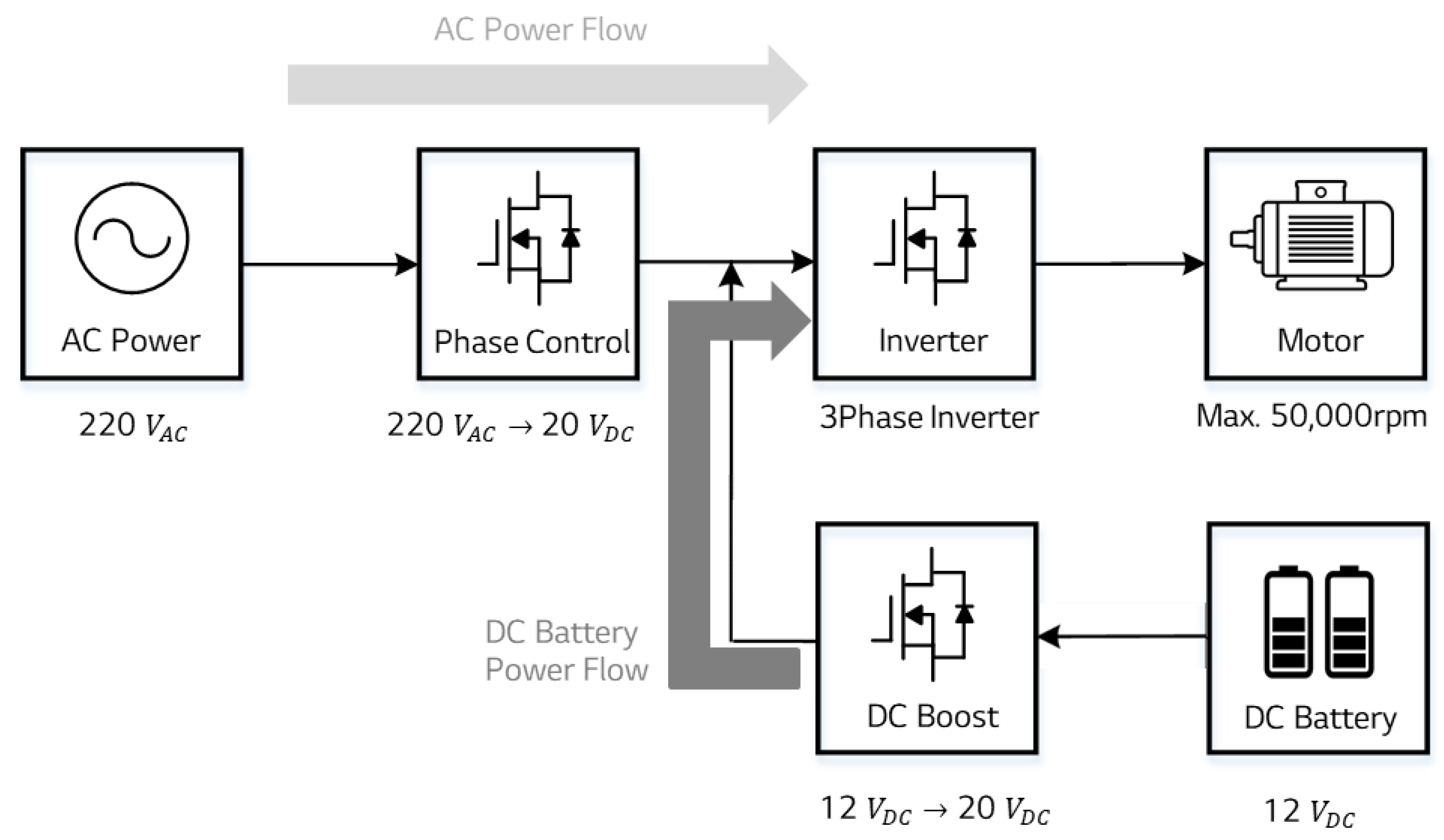
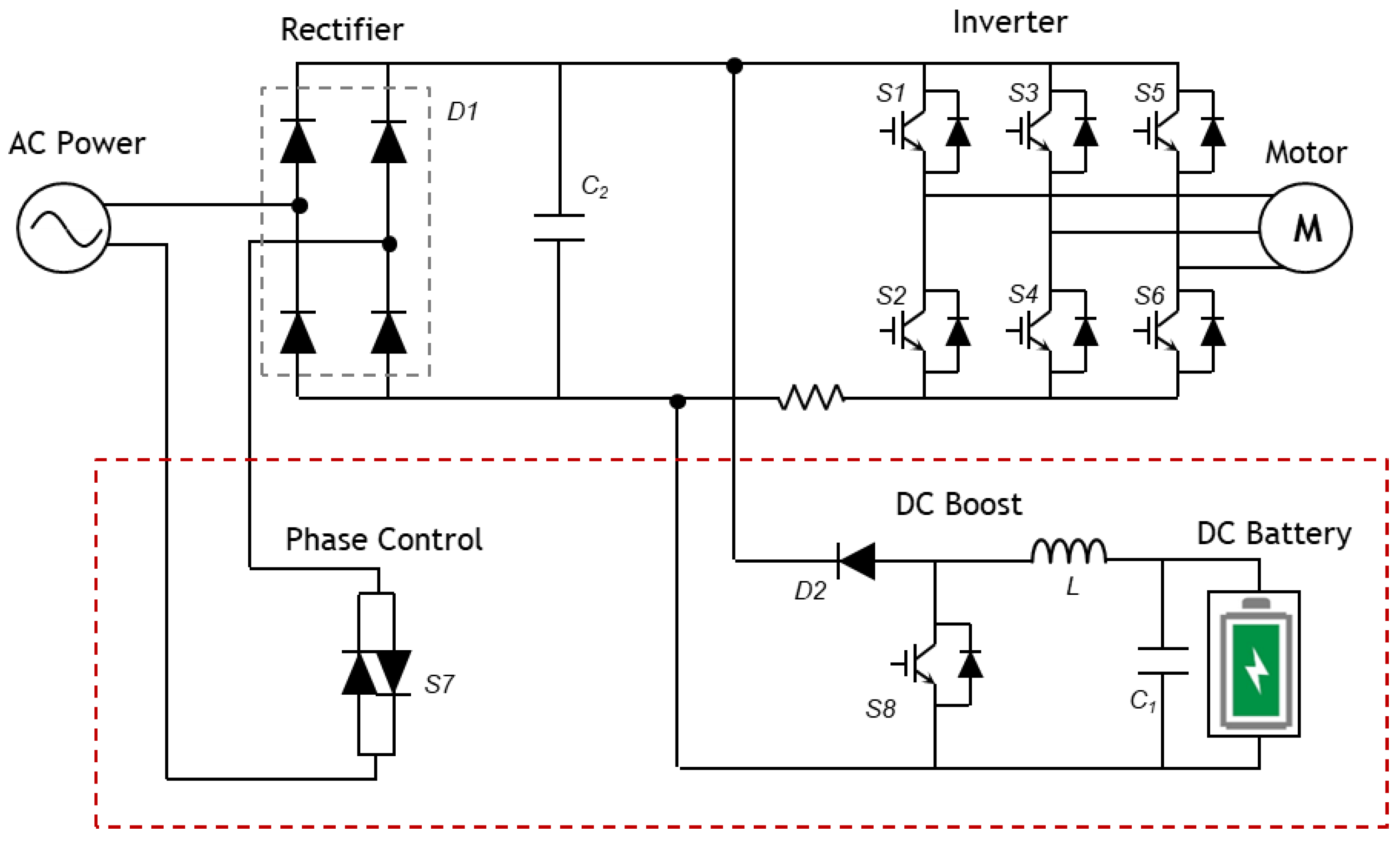
2. System Description
3. Control for Two-Input Power Source
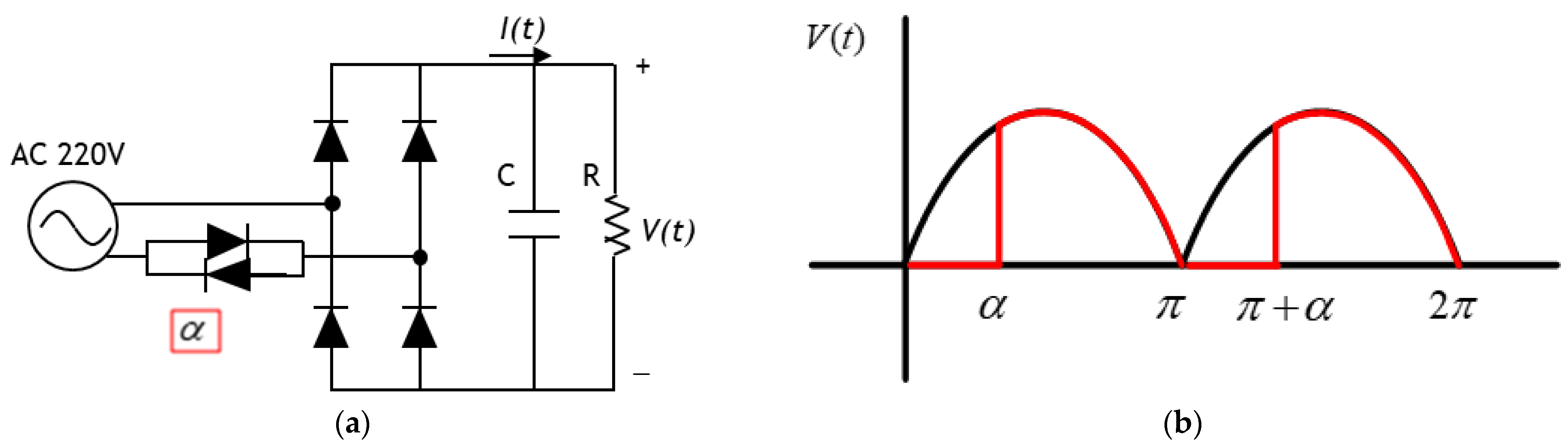
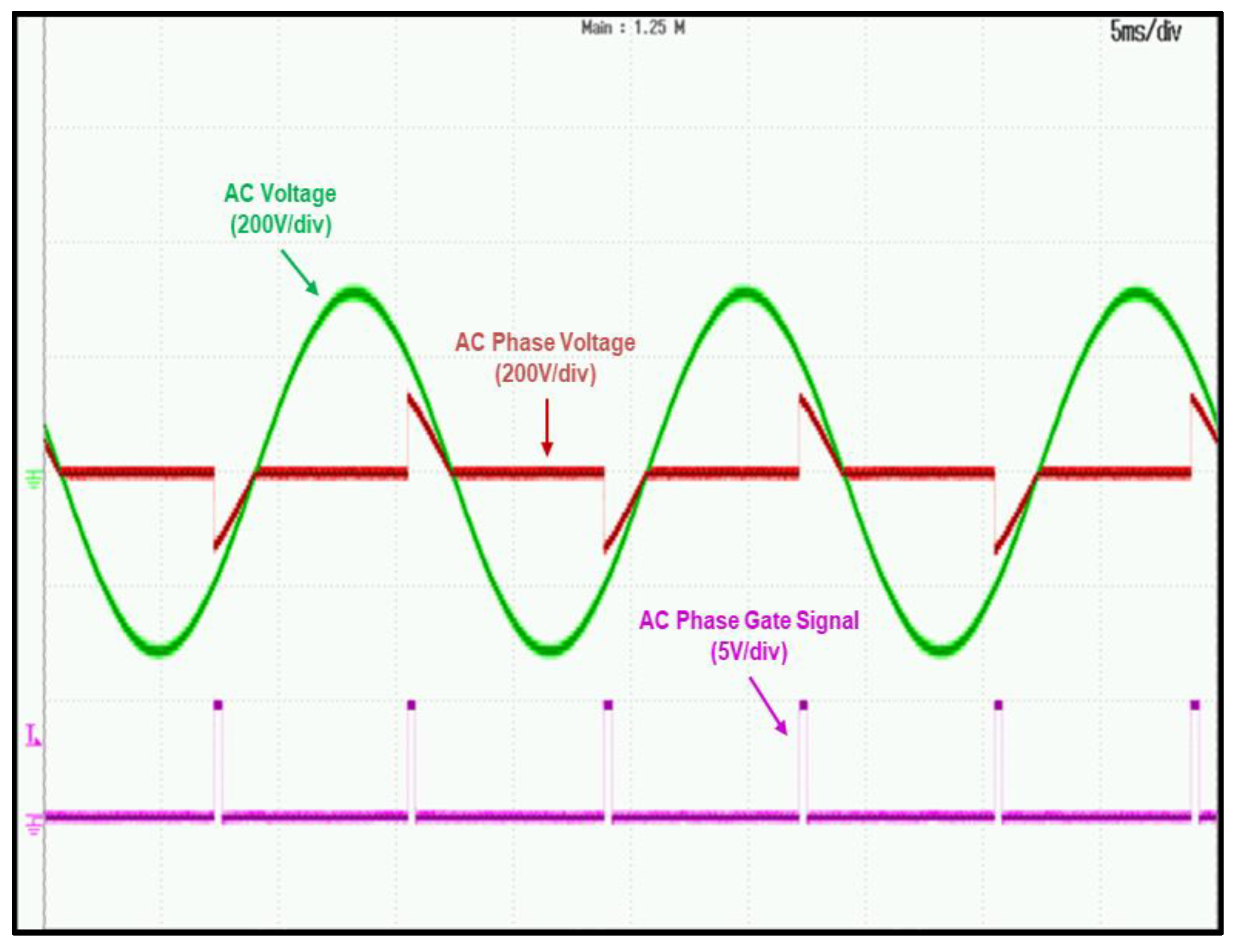
3.1. Phase Control
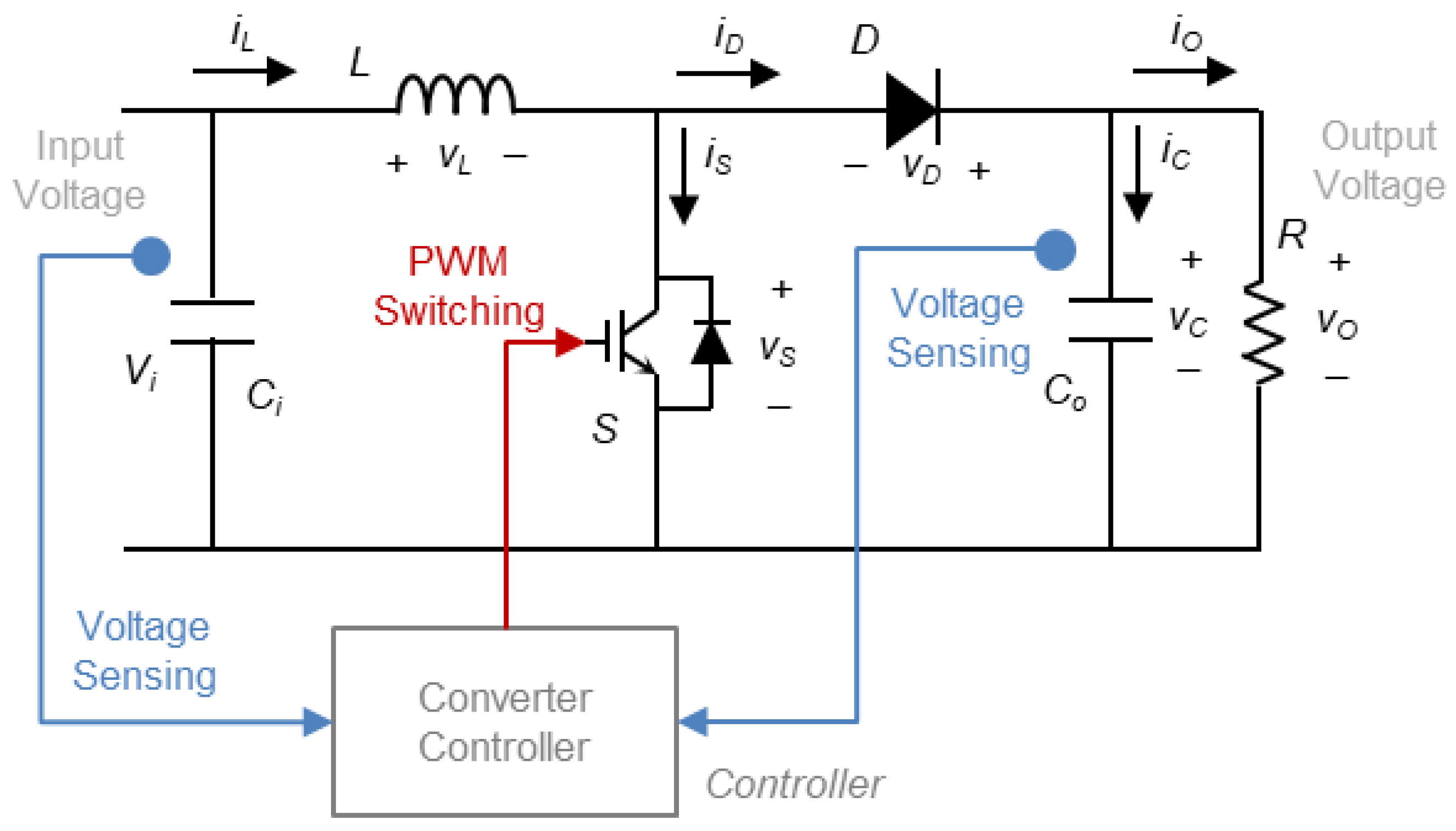
3.2. DC Boost
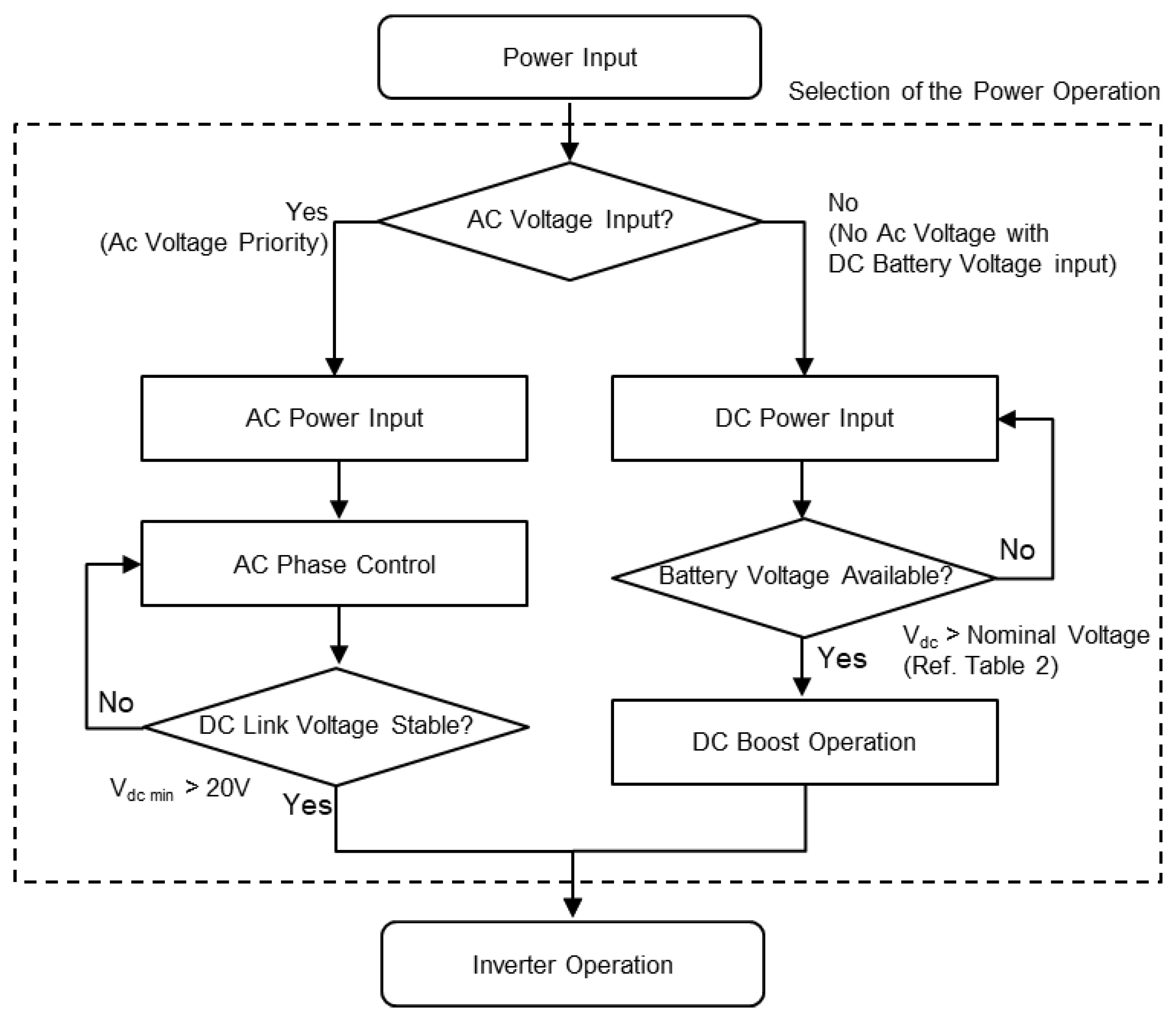
3.3. Control Scheme for Two-Input Power Source
3.3.1. AC Power and DC Battery Motor Driving Method
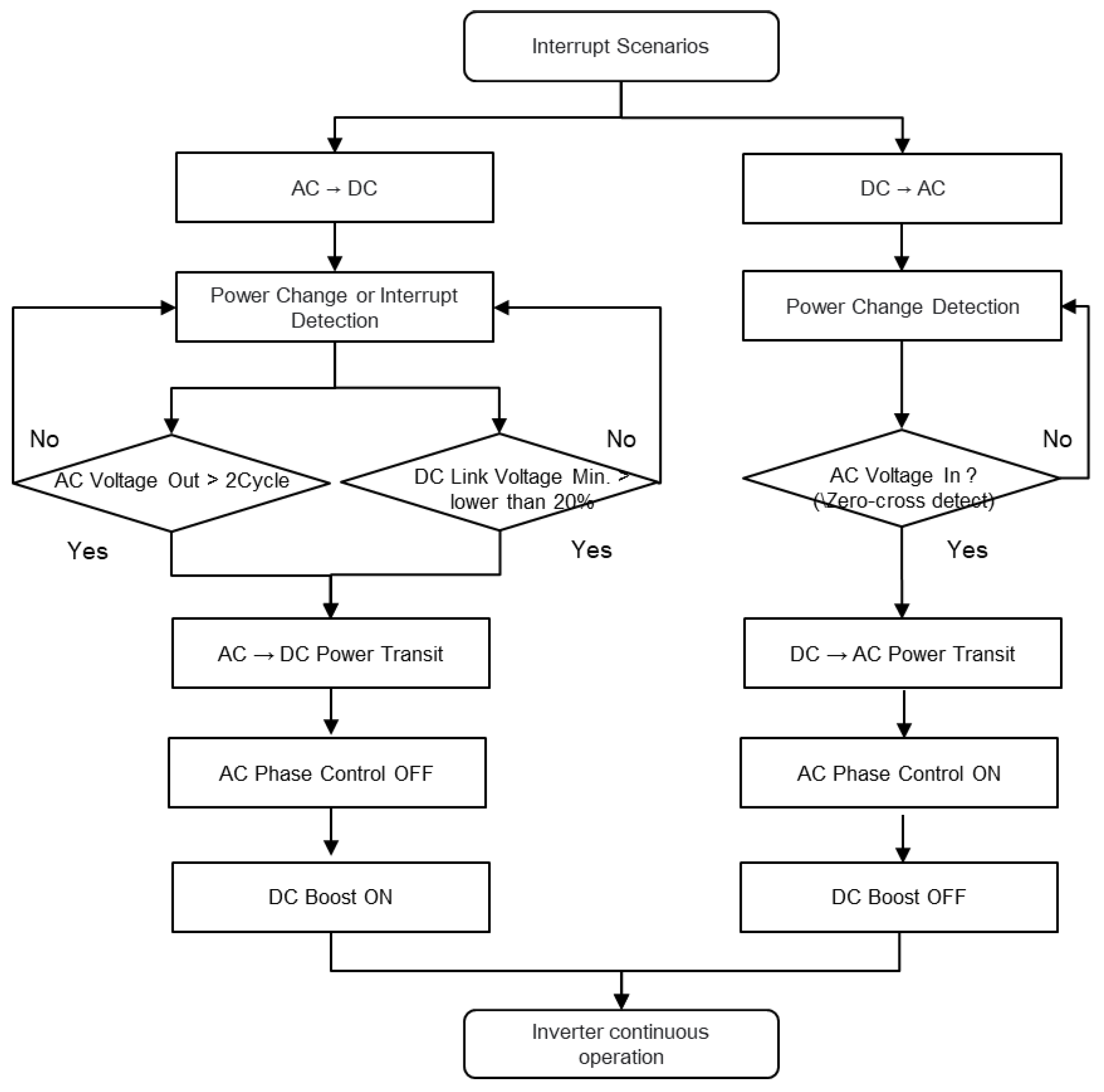
3.3.2. Input Power Change Method (Interrupt Scenarios)
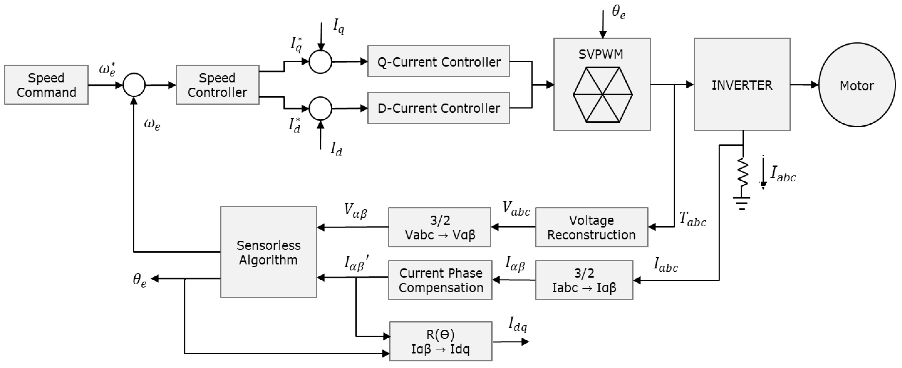
4. Control Scheme for Ultra-High-Speed Sensorless
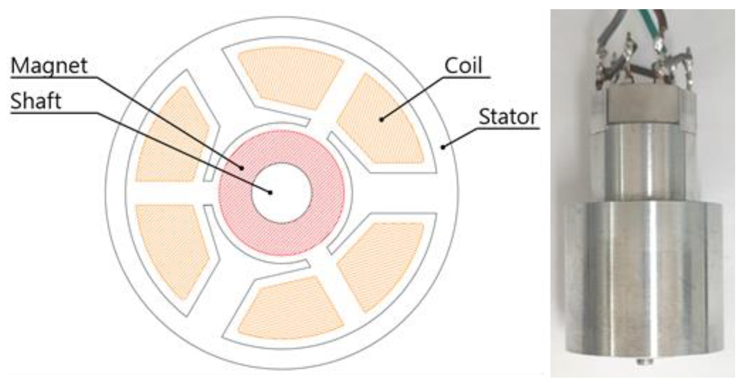
4.1. Motor Design
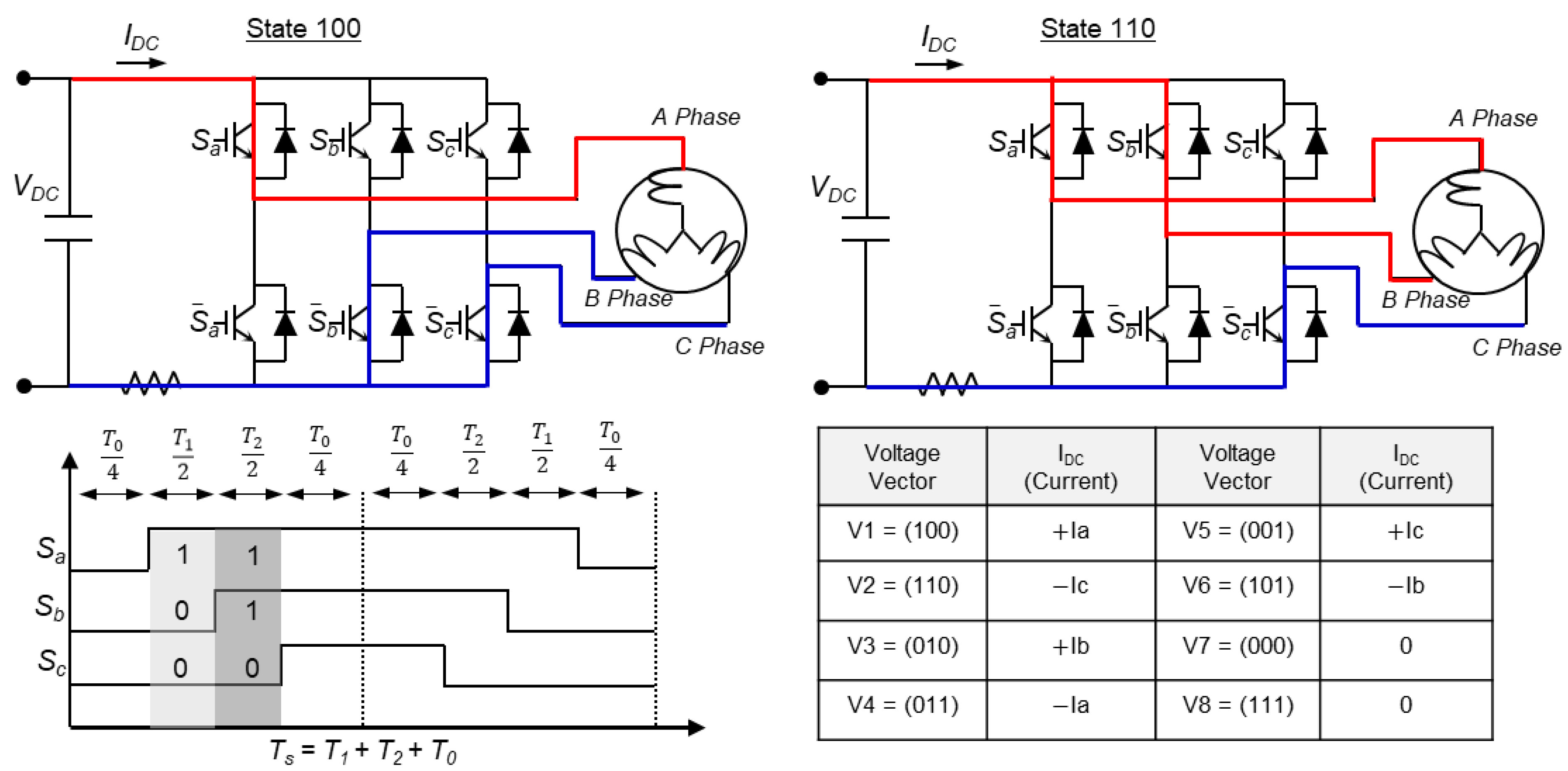
4.2. Proposed Control Scheme
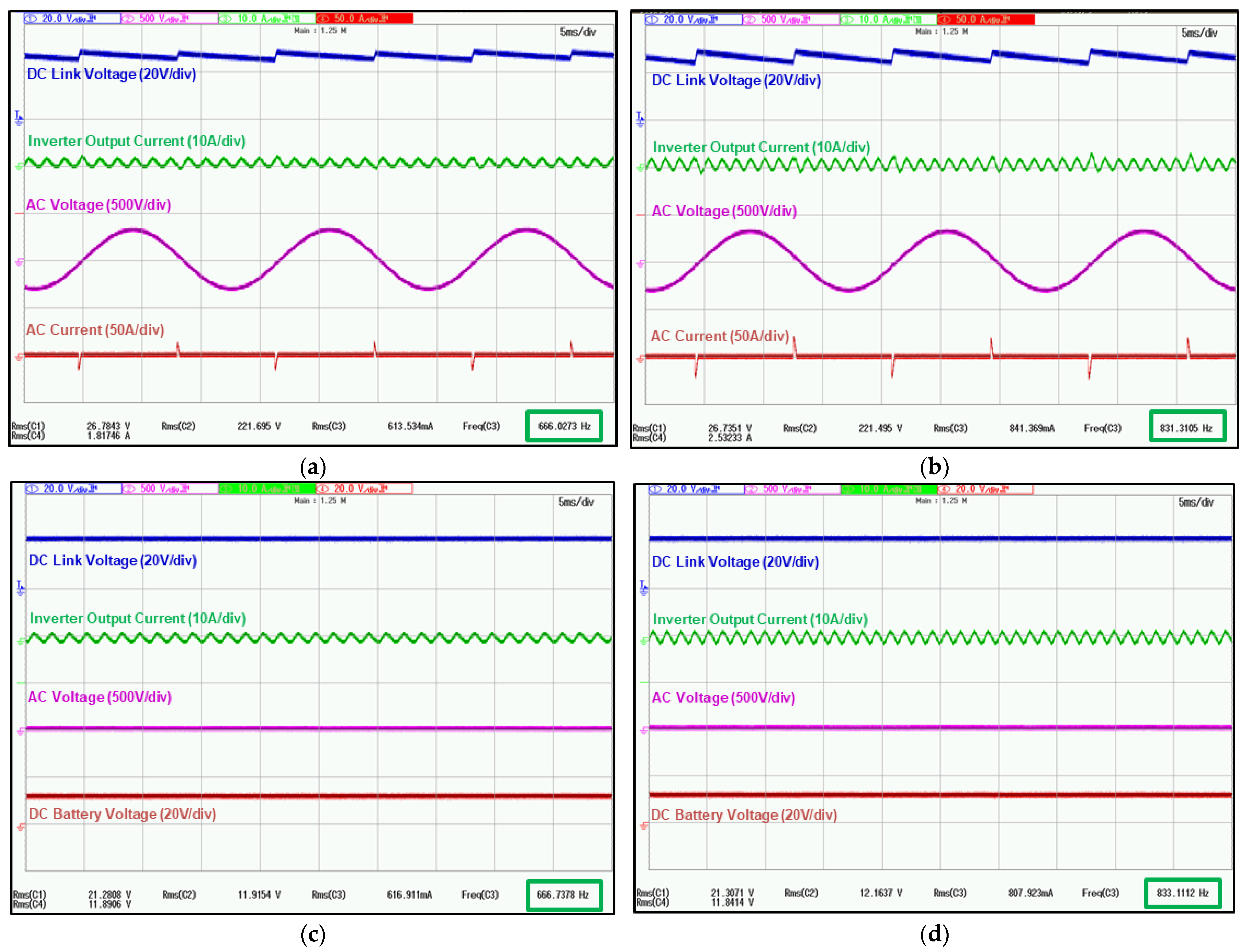
5. Experimental Results
6. Conclusions
Author Contributions
Funding
Conflicts of Interest
References
- Ahmad, F.; Haider, A.A.; Naveed, H.; Mustafa, A.; Ahmad, I. Multiple Input Multiple Output DC to DC Converter. In Proceedings of the 5th International Multi-Topic ICT Conference (IMTIC 2018), Jamshoro, Pakistan, 25–27 April 2018. [Google Scholar]
- Sulaiman, S.; Nair, J.R. Multi-Input Transformer Coupled DC-DC Converter For Rural Electrification Using Renewable Energy Sources. In Proceedings of the IEEE National Conference, Chennai, India, 10–12 October 2014. [Google Scholar]
- Zhang, N.; Sutanto, D.; Muttaqi, K.M. A buck-boost converter based multi-input DC-DC/AC converter. In Proceedings of the IEEE International Conference on Power System Technology (POWERCON), Wollongong, Australia, 28 September–1 October 2016. [Google Scholar]
- Wang, X.; Zhou, S.; Wu, L.; Zhao, M.; Hu, C. Iron Loss and Thermal Analysis of High Speed PM motor Using Soft Magnetic Composite Material. In Proceedings of the 22nd International Conference on Electrical Machines and Systems (ICEMS), Harbin, China, 11–14 August 2019. [Google Scholar]
- Luise, F.; Tessarolo, A.; Pieri, S.; Raffin, P.; Chiara, M.D.; Agnolet, F.; Scalabrin, M. Design and technology solutions for high-efficiency high-speed motors. In Proceedings of the International Conference on Electrical Machines, Marseille, France, 2–5 September 2012. [Google Scholar]
- Burnand, G.; Perriard, Y. Very-High-Speed Miniaturized Permanent Magnet Motors: Design and Optimization. In Proceedings of the Energy Conversion Congress and Exposition (ECCE), Baltimore, MD, USA, 29 September–3 October 2019; pp. 5258–5264. [Google Scholar]
- Chen, J.; Guo, Y.; Zhu, J. Development of a High-Speed Permanent-Magnet Brushless DC Motor for Driving Embroidery Machines. IEEE Trans. Magn. 2007, 43, 4004–4009. [Google Scholar] [CrossRef] [Green Version]
- Parnklang, J.; Seabgsai, T.; Yongyutwichai, K.; Wongprasert, Y. 18650 Battery Real Time Output Resistance Test. In Proceedings of the 5th International Conference on Control and Robotics Engineering (ICCRE), Beijing, China, 24–26 April 2020. [Google Scholar]
- Soto, A.; Berrueta, A.; Sanchis, P.; Ursúa, A. Analysis of the main battery characterization techniques and experimental comparison of commercial 18650 Li-ion cells. In Proceedings of the IEEE Industrial and Commercial Power Systems Europe (EEEIC / I&CPS Europe), Genova, Italy, 10–14 June 2019. [Google Scholar]
- Lin, C.W.; Tzou, Y.Y. Digital voltage control of boost CRM PFC AC/DC converters with TRIAC Phase Control dimmer. In Proceedings of the IEEE International Conference on Power System Technology (POWERCON), Auckland, New Zealand, 23–26 October 2012. [Google Scholar]
- Lü, Z.; Sun, F. Consistent speed control under 220/120Vac power supply. In Proceedings of the International Conference on Electrical and Control Engineering, Yichang, China, 16–18 September 2011. [Google Scholar]
- Jiang, D.; Wang, F. Current ripple prediction for three phase PWM converter. IEEE Trans. Ind. Appl. 2014, 50, 531–538. [Google Scholar] [CrossRef]
- Blasko, V.; Kaura, V.; Niewiadomski, W. Sampling of discontinuous voltage and current signals in electrical drives: A system approach. IEEE Trans. Ind. Appl. 1998, 34, 1123–1130. [Google Scholar] [CrossRef]
- Gu, Y.; Ni, F.; Yang, D.; Liu, H. Switching-State Phase Shift Method for Three-Phase-Current Reconstruction with a Single DC-Link Current Sensor. IEEE Trans. Ind. Electron. 2011, 58, 5186–5194. [Google Scholar]
- Shin, H.J.; Ha, J.I. Phase Current Reconstructions from DC-Link Currents in Three-Phase Three-Level PWM Inverters. IEEE Trans. Power Electron. 2014, 29, 582–593. [Google Scholar] [CrossRef]
- Blaabjerg, F.; Pedersen, J.K.; Jaeger, U.; Thoegersen, P. Single current sensor technique in the DC link of three-phase PWM-VS inverters: A review and a novel solution. IEEE Trans. Ind. Appl. 1997, 33, 1241–1253. [Google Scholar] [CrossRef]
- Fatu, M.; Teodorescu, R.; Boldea, I.; Andreescu, G.D.; Blaabjerg, F. I-F starting method with smooth transition to EMF based motion-sensorless vector control of PM synchronous motor/generator. In Proceedings of the IEEE Power Electronics Specialists Conference, Rhodes, Greece, 15–19 June 2008. [Google Scholar]
- Iepure, L.I.; Boldea, I.; Blaabjerg, F. Hybrid I-f Starting and Observer-Based Sensorless Control of Single-Phase BLDC-PM Motor Drives. IEEE Trans. Ind. Electron. 2012, 59, 3436–3444. [Google Scholar] [CrossRef]
- Morimoto, S.; Kawamoto, K.; Sanada, M.; Takeda, Y. Sensorless control strategy for salientpole PMSM based on extended EMF in rotating reference frame. IEEE Trans. Ind. Appl. 2002, 38, 1054–1061. [Google Scholar] [CrossRef]
- Ichikawa, S.; Tomita, M.; Doki, S.; Okuma, S. Sensorless control of permanent-magnet synchronous motors using online parameter identification based on system identification theory. IEEE Trans. Ind. Electron. 2006, 53, 363–372. [Google Scholar] [CrossRef]
- Taniguchi, S.; Mochiduki, S.; Yamakwa, T.; Wakao, S.; Kondo, K.; Yoneyama, T. Starting procedure of rotational sensorless PMSM in the rotating condition. IEEE Trans. Ind. Appl. 2009, 45, 194–2020. [Google Scholar] [CrossRef]
- Curpertino, F.; Pellegrino, G.; Giangrande, P.; Salvatore, L. Sensorless position control of permanent-magnet motors with pulsating current injection and comparison of motor end effects. IEEE Trans. Ind. Appl. 2011, 47, 1371–1379. [Google Scholar] [CrossRef] [Green Version]
- Zhou, Y.; Long, S. Sensorless direct torque control for electrically excited synchronous motor based on injecting high-frequency ripple current into rotor winding. IEEE Trans. Energy Convers. 2015, 30, 246–253. [Google Scholar] [CrossRef]
- Boldea, I.; Paicu, M.C.; Andreescu, G.D. Active Flux Concept for Motion-Sensorless Unified AC Drives. IEEE Trans. Power Electron. 2008, 23, 2612–2618. [Google Scholar] [CrossRef]
- Holtz, J.; Quan, J. Sensorless vector control of induction motors at very low speed using a nonlinear inverter model and parameter identification. IEEE Trans. Ind. Appl. 2002, 38, 1087–1095. [Google Scholar] [CrossRef]
- Consoli, A.; Scarcella, G.; Testa, A. Industry application of zero-speed sensorless control techniques for PM synchronous motors. IEEE Trans. Ind. Appl. 2001, 37, 513–521. [Google Scholar] [CrossRef]
- Briz, F.; Degner, M.W.; Garcia, P.; Lorenz, R.D. Comparison of saliency-based sensorless control techniques for AC machines. IEEE Trans. Ind. Appl. 2004, 40, 1107–1115. [Google Scholar] [CrossRef]
- Ogasawara, S.; Akagi, H. Implementation and position control performance of a position-sensorless IPM motor drive system based on magnetic saliency. IEEE Trans. Ind. Appl. 1998, 34, 806–812. [Google Scholar] [CrossRef] [Green Version]
- Chen, Z.; Tomita, M.; Doki, S.; Okuma, S. An extended electromotive force model for sensorless control of interior permanent-magnet synchronous motors. IEEE Trans. Ind. Electron. 2003, 50, 288–295. [Google Scholar] [CrossRef]


| Parameter | Model or Value |
|---|---|
| Diode (D1) | DI2010S |
| Power Switch (S1–S6) | BSC054N04NS |
| TRIAC (S7) | BTA316X-800CT |
| Power Switch (S8) | IRLS4030 |
| Diode (D2) | MBRD20U60CT |
| Capacitor (C1) | 50 V/220 uF |
| Capacitor (C2) | 50 V/220 uF × 3 a |
| Inductor (L) | 4.7 uH |
| Parameter | Value |
|---|---|
| Nominal voltage | 3.65 V |
| Maximum voltage | 4.2 V |
| Cut-off voltage | 2.5 V |
| Typical capacity | 2100 mAh |
| Dimension | 18.5 mm × 65 mm |
| Parameter | Value |
|---|---|
| Maximum rotation speed | 50,000 rpm |
| Back electromotive force | 0.3 V peak @ 1000 rpm |
| Phase Resistance | 0.5 Ω |
| Phase Inductance | 0.18 mH |
| Size | Ø 28 × 55 mm |
| Weight | 65 g |
| Parameter | Value |
|---|---|
| AC Voltage and Freq. | 220 V/60 Hz |
| DC Battery Voltage | 12 V |
| Max. Motor Speed | 50,000 rpm |
| Inverter Switching Freq. | 30 kHz |
| DC Boost Switching Freq. | 300 kHz |
| Phase Control Max. Angle | 20° |
Publisher’s Note: MDPI stays neutral with regard to jurisdictional claims in published maps and institutional affiliations. |
© 2022 by the authors. Licensee MDPI, Basel, Switzerland. This article is an open access article distributed under the terms and conditions of the Creative Commons Attribution (CC BY) license (https://creativecommons.org/licenses/by/4.0/).
Share and Cite
Lee, D.-G.; Kim, R.-Y. Design and Control of Ultra-High-Speed Sensorless Drive with Two-Input Power Source for Portable Consumer Electronics. Electronics 2022, 11, 1024. https://doi.org/10.3390/electronics11071024
Lee D-G, Kim R-Y. Design and Control of Ultra-High-Speed Sensorless Drive with Two-Input Power Source for Portable Consumer Electronics. Electronics. 2022; 11(7):1024. https://doi.org/10.3390/electronics11071024
Chicago/Turabian StyleLee, Dong-Geun, and Rae-Young Kim. 2022. "Design and Control of Ultra-High-Speed Sensorless Drive with Two-Input Power Source for Portable Consumer Electronics" Electronics 11, no. 7: 1024. https://doi.org/10.3390/electronics11071024
APA StyleLee, D.-G., & Kim, R.-Y. (2022). Design and Control of Ultra-High-Speed Sensorless Drive with Two-Input Power Source for Portable Consumer Electronics. Electronics, 11(7), 1024. https://doi.org/10.3390/electronics11071024