Abstract
Superconducting magnets with stable and strong magnetic fields play a pivotal role in fields such as biology, medical science, and physics. Given the difficult measurement conditions and low measurement accuracy of the strong magnetic field, a measurement method based on magnetic flux modulation is proposed in this paper. Additionally, a high-stability coil-driving device is established. A circuit for coil speed acquisition and measurement is developed. The effective values of induced electromotive forces corresponding to the measured strong magnetic field are obtained, following the de-noising principle of the lock-in amplifier. Particularly, a traceable transmission standard is formed when the measurement coil is calibrated by the national standard magnetic field. The experimental system results demonstrated that the uncertainty of the proposed method reaches the order of E-4 for the measurement of magnetic induction intensity below 7T. This significantly contributes to the measurement of superconducting strong magnetic fields.
1. Introduction
The extreme experimental conditions generated by a strong magnetic field provide new opportunities for basic scientific research work, and the related experimental device has become a recognized “national weapon” for exploring scientific treasures in scientific and technological fields [1]. The “fractional quantum Hall effect” [2] that won the Nobel Prize in Physics at the end of the 20th century benefited from a strong magnetic environment. Magnet devices generating a strong magnetic field can be divided into three types: water-cooled magnets (also called resistive magnets), superconducting magnets, and hybrid magnets. Among them, the superconducting magnet requires a small excitation current source power, does not need the large water supply and purification equipment of conventional magnets, and can provide a stable and strong magnetic field for a long time. It plays a crucial role in the fields of biology, medical science, and physics [3,4,5,6]. At present, many countries have established increasingly strong magnetic field laboratories. For example, the US High Field Laboratory (NHMFL) developed a superconducting magnet system in 2012 to produce 32 T [7]. The Japan Institute of Physics and Chemistry (RIKEN) produced a 28 T high-temperature interpolated magnet with high uniformity using layer winding [8,9,10]. The F71 multi-axis gauss meter with the Hall probe, developed by the Lakeshore Company, can measure a strong magnetic field of up to 35T [11]. The team at the Institute of Electrical Engineering, Chinese Academy of Sciences, used high-temperature interpolated magnet technology to develop an all- superconducting magnet with a central magnetic field of up to 32.35 T [12].
The accurate measurement of strong magnetic fields is an essential prerequisite for conducting scientific research in a strong magnetic field environment. Thus, Miyagi et al. developed a high-flux density magnet measurement system by using a new sheet tester [13]. The system verifies the accuracy of the measurement of alternating current (AC) loss at high magnetization (55,000 A/m) by measuring the eddy current loss of a copper plate compared with the theoretical value. It is shown that the magnetic properties of non-oriented electrical steel sheets can be measured until 2.1 T. Wang Xiaofei et al. employed the method of field magnetic resonance to achieve a stable magnetic field measurement [14]. Wang Yueyi et al. measured the capacitance change induced by the magnetic field generated Lorentz force to drive the flat plate periodically, by reversing the magnetic field size, with the measurement range reaching 0.05–1.50 T [15]. Academician Zhang Zhonghua et al. established a national standard for superconducting strong magnetic fields and achieved a magnetic induction measurement by tracing the physical constant of the proton gyromagnetic ratio [16]. Moreover, they realized the magnetic induction intensity measurement by tracing the physical constant of the proton gyromagnetic ratio [17]. Nevertheless, this method requires high magnetic field uniformity and heavy water probes under strong magnetic fields.
In this study, based on magnetic flux modulation technology, an induction coil is independently winded, a high-stability coil-driving device is developed, and a coil speed collection and measurement circuit is designed. Following the principle of lock-in amplifier denoising, the noisy induced electromotive force is used as the input signal. Meanwhile, the actual speed of the coil is obtained through the encoder and converted by the measuring circuit to form a reference signal. The effective value of the induced electromotive force related to the intensity of the measured strong magnetic field is acquired. After the induction coil is traced and calibrated in the national standard magnetic field, its measurement uncertainty reaches the level of E-4. This method has the advantages of simple operation and wide measurement range and significantly contributes to the measurement of superconducting strong magnetic fields.
2. Principle of Magnetic Flux Modulation
A coil with N turns and a cross-sectional area S is placed in a superconducting uniform strong magnetic field with a magnetic induction intensity of B. The magnetic flux Φ of the coil changes when it is rotating at an angular velocity , perpendicular to the direction of the magnetic field. According to Faraday’s law of electromagnetic induction, the induced electromotive force E(t) is expressed as follows:
Under the known N, S, and , the field strength B of the magnetic field to be measured can be obtained by collecting the E(t) generated by the coil, namely,
3. Measuring System Design
Figure 1 illustrates a schematic diagram of the composition of a strong magnetic field measurement system. The system is composed of three parts: a coil-driving device, a strong magnetic field to be measured, and a signal acquisition and processing unit. The coil driving device consists of a servo motor, its driver, a transmission shaft, a bracket, a vibration-damping mechanism, and a coil. Among them, the servo motor and the coil are connected by a transmission shaft with a length of about 2 m to eliminate the mutual influence between the servo motor and the strong magnetic field to be measured. Additionally, an orthogonal rotation speed conversion mechanism is designed at the end of the transmission shaft to realize the continuous movement of the coil cutting the magnetic line of induction in the measuring hole of the strong magnetic field to be measured. Moreover, the noise removal principle of the lock-in amplifier is adopted to accurately measure the induced electromotive force of the rotating coil. First, the noise-containing induced electromotive force is used as the input signal. Then, the actual speed of the coil is obtained through the encoder and converted by the measuring circuit to form a reference signal. Finally, the effective value of the induced electromotive force after denoising is acquired. After the rotating coil is calibrated by the standard strong magnetic field, the magnetic field strength to be measured can be calculated according to Equation (2).
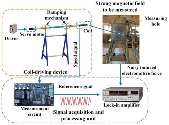
Figure 1.
Schematic diagram of the strong magnetic field measurement system.
3.1. Coil-Driving Device
Considering that the stability of the coil rotation speed directly affects the accuracy of the measurement results, a servo motor with good speed performance and strong load capacity is employed as the driving power source of the coil. It can effectively control the coil to rotate at a uniform speed in the center of the magnetic field to be measured. By adjusting the control parameters, such as the drive speed loop gain and integral time, the error between the actual speed and the set speed of the motor can be maintained within 2 rpm, as presented in Table 1.

Table 1.
Motor speed error at different speeds.
Moreover, a 10:1 reducer is installed at the servo motor to further improve the overall performance of the entire drive unit. In this way, the output torque is boosted, while the transmission error of the coil-driving unit is reduced to one-thousandth.
As illustrated in Figure 2, the coil used in the experiment is made of enameled wire wound on a non-magnetic pure resin skeleton, with an inner diameter of 6 mm, an outer diameter of 15 mm, and a wall thickness of 1 mm at both ends. There is a total of 400 turns. The coil is connected to the external non-magnetic resin wireframe through a bearing and passes a rotational speed orthogonal conversion mechanism composed of a turbine worm and a belt. The coil is driven by a servo motor to realize the continuous cutting of the magnetic induction line movement in the strong magnetic field to be measured. Moreover, a specially designed conductive slip ring is installed between the coil and the non-magnetic wireframe to smoothly lead the induced electromotive force signal on the coil to the lock-in amplifier.
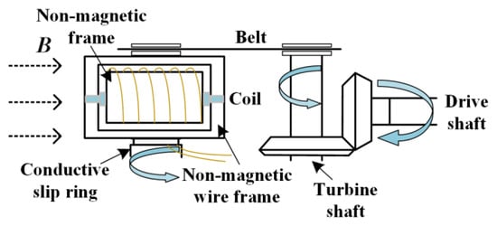
Figure 2.
Coil probe structure diagram.
3.2. Experimental System for Measuring the Strong Magnetic Field
The experimental system is illustrated in Figure 3. The left side shows the superconducting magnet generation system. The right side shows the coil-driving device, which drives the coil to cut the magnetic lines of induction at a constant speed in the measuring hole, located at the center of the magnet generation system. An encoder is installed at the rotating end of the coil to obtain the angular displacement of the coil in real time.
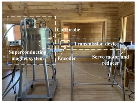
Figure 3.
Actual measurement system.
A strong magnetic field of up to 7 T can be generated by such superconducting strong magnetic field equipment, which is composed of a low-temperature vacuum system, a circulating water refrigeration unit, a mechanical pump, a molecular pump, a superconducting magnet, and a direct current source. Before the excitation, the mechanical pump and the molecular pump cooperate to pump the magnet space into an ultra-high vacuum state. Meanwhile, the refrigerator lowers the temperature of the magnet system to below 4 K. The excitation is conducted to produce a stable superconducting strong magnetic field. The output signal of the encoder is processed by the measuring circuit and connected to the lock-in amplifier to obtain the effective value of the induced electromotive force. Then, the magnitude of the measured strong magnetic field is characterized.
3.3. Signal Acquisition and Processing Unit
Figure 4 shows that this paper is based on the principle of lock-in amplifier denoising. First, the noisy induced electromotive force is used as the input signal. Next, the actual speed of the coil is obtained through the encoder and converted by the measuring circuit to form a reference signal. After its internal phase-sensitive detection and low-pass filtering, the AC component voltage U(t) output by the lock-in amplifier is
where and r indicate the phases of the input signal and the reference signal, respectively; Vi and Vref denote the input signal and reference signal amplitude, respectively. U(t) is half of the product of the input signal and the reference signal amplitude- when its phase difference is zero. Specifically, a high-speed position encoder TS5700N5801 is installed at the rotating position of the coil to accurately obtain the reference signal.
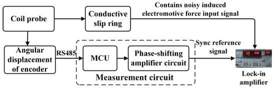
Figure 4.
Signal processing flow.
A special measurement circuit is developed to convert the position signal into an analog reference sine wave, with the same frequency and phase as the coil speed in real time, through digital-to-analog conversion and phase-shifting amplification. After these two signals are connected to the SR830 lock-in amplifier, the effective induced electromotive force signal, with the same frequency as the reference signal, is separated from the noise interference.
The measurement circuit is composed of modules such as power management, RS485 communication, STM32 microprocessor minimum system, DAC conversion, and phase-shifting amplification. The circuit design block diagram and the PCB board are shown in Figure 5. Its main functions include: (1) receiving the coil rotation angle displacement signal collected by the encoder; (2) processing the position signal into an analog sine signal consistent with the coil rotation frequency; (3) outputting an analog sine reference wave with the same frequency and phase as the coil electromotive force after phase shifting and amplification.
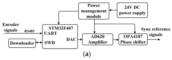
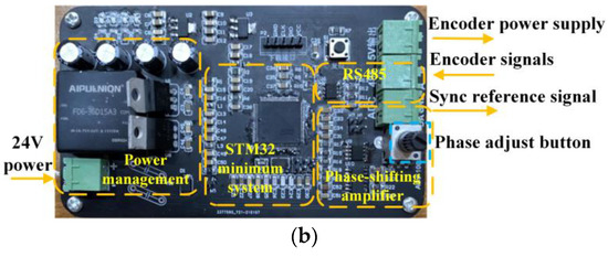
Figure 5.
Sync reference signal acquisition circuit: (a) block diagram of circuit design; (b) PCB circuit diagram.
4. Experimental Data Processing and Error Analysis
4.1. Estimation and Calibration of the Effective Area of the Coil
The product of the number of coil turns and the effective area is called the coil constant NS, which is a key indicator of the coil performance. The traceable calibration of this constant determines the accuracy of the strong magnetic field measurement method based on the electromagnetic induction principle.
4.1.1. NS Estimate
The inner and outer diameters of the coil are d1 = 6 mm and d2 = 15 mm, respectively. The number of turns N is 400. The estimated value of the effective area of the coil NSe is
NSe is only used as a verification of the order of magnitude of the effective area of the coil instead of the effective area of the coil during actual measurement. It must be calibrated traceably.
4.1.2. NS Calibration
China’s superconducting strong magnetic field measurement standard was established by the Chinese Academy of Metrology. With the frequency and gyromagnetic ratio of the radio frequency field in nuclear magnetic resonance, the absolute value of the strong magnetic field is measured in the range of 2–12 T, with an accuracy of 6 × 10⁻⁵. Additionally, the error range is verified by circumstantial experiments [18].
In this study, the effective area NS of the coil is calibrated by measuring the effective value of the electromotive force of the coil in the standard superconducting strong magnetic field. First, a stable and strong magnetic field of 0.5 T is generated by the superconducting magnet device. Then, the coil speed is set to 60 r/min. The effective value of the induced electromotive force is recorded every 1 min, for a total of 14 times, as provided in Table 2.
Table 2.
Collected values of the induced electromotive force.
As observed in Table 2, the average effective value of the electromotive force at this time is = 68.43 mv, and the final coil constant NS is
where B = 0.5 T and ω = 2πf = 2π rad/s. Then, NS = 3.08 × 10⁻² m2 can be obtained. This value is consistent with NSe. During the process of estimating the coil constant, the multi-turn coil is regarded as a continuous whole, and the gap between the individual turns is ignored. Thus, NSe is larger than the actual calibration NS.
4.2. Analysis of Results
4.2.1. Relative Error of Measurement
The coil rotation frequency is set to 1 Hz. The strong magnetic field generated by the superconducting magnet system (Figure 5) is independently measured by the nuclear magnetic resonance measuring instrument and the measurement system developed in this paper. The measurement results are listed in Table 3.
Table 3.
Magnetic field measurement results.
Table 3 reveals that the calculated value of magnetic field intensity is close to the measured value of nuclear magnetic resonance, with a relative error of less than 1‰. This effectively verifies the feasibility of the designed strong magnetic field measurement system.
4.2.2. Measurement Uncertainty
The measurement uncertainty of the strong magnetic field measurement system is majorly reflected in the calibration uncertainty of the coil effective area NS, including the following two parts:
- (1)
- Standard Uncertainty of Type A
The type A standard uncertainty of the effective area of the coil NS is derived from the induced electromotive force collected in the calibration experiment. uE is expressed as
By substituting the data in Table 2 into Equation (6), the standard uncertainty of Type A, introduced by the average value of the electromotive force, is obtained to be uE = 6.5 × 10⁻⁴.
- (2)
- Standard Uncertainty of Type B
Due to the changes in ambient temperature and magnetization, the coil may be deformed. However, the coil bobbin is made of pure resin non-magnetic materials, and the experimental environment temperature is relatively constant. Thus, the type B standard uncertainty introduced in this section is estimated to be ut = 1 × 10⁻⁴.
Under the combination of the above two types of uncertainties, the final uncertainty uc of the strong magnetic field measurement system is
5. Conclusions
Based on the principle of magnetic flux modulation, a strong magnetic field measurement system, composed of a coil-driving device and a signal acquisition and processing unit, is designed in this paper. Moreover, a superconducting strong magnetic field measurement experiment is conducted. The conclusions are drawn as follows.
- (1)
- The coil-driving device connects the servo motor and the coil through a non-magnetic stainless steel drive shaft with a length of 2 m to eliminate the mutual influence between the servo motor and the strong magnetic field to be measured as much as possible. After a 10:1 reducer is assembled at the end of the servo motor, the coil speed error can be reduced to less than one-thousandth;
- (2)
- The signal acquisition and processing circuit can output a reference analog sine wave with the same frequency and phase as the coil electromotive force;
- (3)
- After the calibration of the coil constant NS in a standard magnetic field, a traceable transmission standard is established to significantly improve the accuracy of the strong magnetic field measurement system;
- (4)
- The results demonstrate that the final uncertainty of the strong magnetic field measurement system can reach the order of E-4. This highly contributes to the measurement of the superconducting strong magnetic field.
Author Contributions
Data curation, Z.L. (Zhun Li) and Z.L. (Zengkun Leng); Formal analysis, Z.L. (Zhun Li), Y.L. and Z.O.; Investigation, Z.O. and Y.L.; Methodology, Y.L. and Z.Y.; Project administration, Y.L.; Resources, S.Z.; Software, Z.L. (Zengkun Leng); Supervision, Y.L. and Z.Y.; Visualization, Z.L. (Zengkun Leng); Supervision, Y.L. and Z.Y. Validation, Z.L. (Zhun Li), Y.Z. and Z.Y. Writing—original draft, Z.L. (Zhun Li) and S.Z.; Writing—review and editing, Z.L. (Zengkun Leng) and Z.Y. All authors have read and agreed to the published version of the manuscript.
Funding
This work was funded by the National Natural Science Foundation of China, grant number NSFC 51777199.
Institutional Review Board Statement
Not applicable.
Informed Consent Statement
Not applicable.
Data Availability Statement
The data presented in this study are available on request from the corresponding author. The data are not publicly available due to privacy.
Conflicts of Interest
Authors declare no conflict of interest.
References
- Ku, G.L.; Shao, S.F. Steady-state strong magnetic field technology and its scientific significance. Sci. Technol. Rev. 2018, 36, 93–96. [Google Scholar]
- Stormer, H.L.; Tsui, D.C. The fractional quantum Hall effect. Proc. Natl. Acad. Sci. USA 1987, 84, 4696–4697. [Google Scholar] [CrossRef] [Green Version]
- Yao, Y. The Research of Detection and Application Technology of Weak Magnetic Field. Master’s Thesis, Wuhan University of Technology, Wuhan, China, 2002. [Google Scholar]
- Caruso, M.J.; Smith, C.H.; Bratland, T.; Schneider, R. A new perspective on magnetic field sensing. Sensors 2010, 15, 236–250. [Google Scholar]
- Frollo, I.; Andris, P.; Krafcilk, A. Magnetic and Electric Fields Measurements. In Proceedings of the 11th International Conference on Measuremnet, Smolenice, Slovakia, 29–31 May 2017; pp. 259–262. [Google Scholar]
- Xu, Z.; Liu, J.; Zhang, X.X. Bio-magnetic field intensity detector for magnetic field produced by magnetotactic bacterium. Mod. Electron. Tech. 2013, 36, 29–34. [Google Scholar]
- Markiewicz, W.D.; Larbalestier, D.C.; Weijers, H.W.; Voran, A.J.; Pickard, K.W. Design of a superconducting 32 T magnet with REBCO high field coils. IEEE Trans. Appl. Supercond. 2012, 22, 4300704. [Google Scholar] [CrossRef]
- Kiyoshi, T.; Choi, S.; Matsumoto, S.; Zaitsu, K.; Hase, T.; Miyazali, T.; Hamada, M.; Hosono, M.; Maeda, H. Bi-2223 innermost coil for 1.03 GHz NMR magnet. IEEE Trans. Appl. Supercond. 2011, 21, 2110–2113. [Google Scholar] [CrossRef]
- Matsumoto, S.; Kiyoshi, T.; Otsuka, A.; Hamada, M.; Maeda, H.; Yanagisawa, Y.; Nakagome, H.; Suematsu, H.S. Generation of 24 T at 4.2 K using a layer-wound GdBCO insert coil with Nb3Sn and Nb–Ti external magnetic field coils. Supercond. Sci. Technol. 2012, 25, 108–112. [Google Scholar] [CrossRef]
- Yanagiawa, Y.; Xu, Y.; Iguchi, S. Combination of high hoop stress tolerance and a small screening current-induced field for an advanced Bi-2223 conductor coil at 4.2K in an external field. Supercond. Sci. Technol. 2015, 28, 125005. [Google Scholar] [CrossRef]
- Lake Shore. F71 Multi-Axis Teslameter. Available online: https://www.lakeshore.com/products/categories/specification/magnetic-products/gaussmeters-teslameters/f71-and-f41-teslameters (accessed on 1 October 2020).
- Liu, J.H.; Wang, Q.L.; Qin, L.; Zhou, B.Z. World record 32.35-tesla direct-current magnetic field generated with whole superconductor magnet. Supercond. Sci. Technol. 2020, 33, 03LT01. [Google Scholar] [CrossRef]
- Miyagi, D.; Yamazaki, T.; Otome, D.; Nakano, M. Development of measurement system of magnetic properties at high flux density using novel single-sheet tester. IEEE Trans. Magn. 2009, 45, 3889–3892. [Google Scholar] [CrossRef]
- Wang, X.F. Weak Magnetic Field Measurements of Magnetic Resonance Samples via Atomic Magnetometers. Master’s Thesis, University of Chinese Academy of Sciences, Beijing, China, 2019. [Google Scholar]
- Wang, Y.Y.; Xu, G.B.; Wang, C.C.; Chen, X.; Ma, Y.M. Structure design and characteristic analysis of a planar torsional micro sensor for strong magnetic field measurement. J. Hefei Univ. Technol. (Nat. Sci.) 2020, 10, 1352–1356. [Google Scholar]
- Zhang, Z.H.; Wang, D.A.; Hu, Z. China’s superconducting strong magnetic field test standard. Electr. Meas. Instrum. 1989, 12, 3–8. [Google Scholar]
- Liu, J.Y. Research and Design of the Proton Precession Magnetometer Sensor. Master’s Thesis, Jilin University, Changchun, China, 2015. [Google Scholar]
- Wang, S.H. Research on the Magnetic Field Measurement Standards and Traceability Technology of Magnetic Resonance Imaging. Master’s Thesis, Hebei University, Baoding, China, 2014. [Google Scholar]
Publisher’s Note: MDPI stays neutral with regard to jurisdictional claims in published maps and institutional affiliations. |
© 2022 by the authors. Licensee MDPI, Basel, Switzerland. This article is an open access article distributed under the terms and conditions of the Creative Commons Attribution (CC BY) license (https://creativecommons.org/licenses/by/4.0/).