Article

Controller Design of Tracking WMR System Based on Deep Reinforcement Learning

1
Department of Electronic Engineering, National Quemoy University, Jinning 892009, Taiwan
2
Department of Electrical Engineering, National Chin-Yi University of Technology, Taichung City 411030, Taiwan
*
Author to whom correspondence should be addressed.
Electronics 2022, 11(6), 928; https://doi.org/10.3390/electronics11060928
Submission received: 10 February 2022 / Revised: 9 March 2022 / Accepted: 15 March 2022 / Published: 16 March 2022
(This article belongs to the Special Issue Wireless Sensor Networks Applications in Internet of Things)

Abstract

:
Traditional PID controllers are widely used in industrial applications due to their simple computational architecture. However, the gain parameters of this simple computing architecture are fixed, and in response to environmental changes, the PID parameters must be continuously adjusted until the system is optimized. This research proposes to use the most important deep reinforcement learning (DRL) algorithm in deep learning as the basis and to modulate the gain parameters of the PID controller with fuzzy control. The research has the ability and advantages of reinforcement learning and fuzzy control and constructs a tracking unmanned wheel system. The mobile robotic platform uses a normalization system during computation to reduce the effects of reading errors caused by the wheeled mobile robot (WMR) of environment and sensor processes. The DRL-Fuzzy-PID controller architecture proposed in this paper utilizes degree operation to avoid the data error of negative input in the absolute value judgment, thereby reducing the amount of calculation. In addition to improving the accuracy of fuzzy control, it also uses reinforcement learning to quickly respond and minimize steady-state error to achieve accurate calculation performance. The experimental results of this study show that in complex trajectory sites, the tracking stability of the system using DRL-fuzzy PID is improved by 15.2% compared with conventional PID control, the maximum overshoot is reduced by 35.6%, and the tracking time ratio is shortened by 6.78%. If reinforcement learning is added, the convergence time of the WMR system will be about 0.5 s, and the accuracy rate will reach 95%. This study combines the computation of deep reinforcement learning to enhance the experimentally superior performance of the WMR system. In the future, intelligent unmanned vehicles with automatic tracking functions can be developed, and the combination of IoT and cloud computing can enhance the innovation of this research.

1. Introduction

In response to Industry 4.0, the application studies of the Internet of Things and intelligent robots have been popular subjects for industrial and academic development. The wheeled mobile robot (WMR) tracking system, which can be extensively used in path following and control of domestic robots [1], transport robots [2], unmanned vehicles [3], and navigation systems [4], has become one of the major research focuses of related technical fields. At present, common WMRs mostly use black adhesive tape, walls, or other media with feature recognition, to form the path planning of a tracking system [5], and uses infrared reflective [6], ultrasound [7], laser ranging, image recognition [8], or the feature medium recognition of gas detection to obtain the real-time position of WMR and to control tracking [9].
In the tracking control of WMR, a simple method is to use a digital transducer, which only judges “white” and “black” (0 and 1) modes for path following. While such a two-value logic judgment method is relatively easy, control accuracy and stability are not ideal; therefore, it is often used in basic program education for schoolchildren in practical applications [10]. Another method is to partition several gray level-like sensing blocks between “white” and “black” (0 and 1), meaning the real-time position of the WMR is judged more accurately according to the signal intensity detected by the sensor, and the corresponding output is made for the motor according to the operation of the controller. This operational method is often combined with PID control, fuzzy control, and an artificial neural network algorithm. As the amount of computation is huge, it can be implemented by a combinational logic circuit, microcontroller, microprocessor, and field programmable gate array (FPGA), and the control effect is much better than two-value logic [11]. Therefore, it has been extensively used in practical applications.
It is known that the conventional PID controller has been universally used in industry for its simple computing architecture; however, as the control loop uses fixed gain parameters, the complex system is sometimes over-controlled, and stability is poor. In order to remedy such defects, conventional PID control is combined with fuzzy control in this paper, the Fuzzy-PID controller is designed for WMR tracking, and the mBot robot kit, as produced by the Makeblock Company, is used as the test platform for our Fuzzy-PID controller. The mBot robot kit is a perfect educational kit combining metal blocks, a sensing module, development software, and peripheral tools, which supports the graphical programming environment of Scratch [12]. Thus, it has become the key teaching material of STEM education [13]. However, in the Me-Line-Follower kit of the Makeblock Company, the design of the sensing module is the digital two-value logic judgment of a Schmitt trigger with an IR sensor, and even though there are five sensors, fine control fails; thus, the tracking effect is poor. Therefore, the conventional PID control and fuzzy control were combined in this study, and three CNY70 IR sensors were used to test the gray area between “black” and “white” (1 and 0) in order to provide a Fuzzy-PID controller with more precise tracking operation. Finally, the mBot platform was used for our Fuzzy-PID controller’s step function and complex path tracking test. The experimental results showed that the Fuzzy-PID controller design proposed in this paper performs better than the conventional PID controller in tracking stability, maximum overshoot, and tracking time during step response and site tracking testing.
The main contribution of this research is to use the fuzzy control based on deep reinforcement learning (DRL) algorithm combined with PID control to make the automatic tracking unmanned vehicle developed in this research with intelligent ability. Compared with the existing related literature research, the accuracy and efficiency of traditional PID control are improved by 15.2%, and the tracking time is also shortened by 6.78%. The convergence time is about 0.5 s. In addition, the deep augmentation fuzzy control adopted in this study can simplify the system’s nonlinear complexity and improve the WMR system’s adaptability. Control of mechanism dynamics can give more precise automatic control. This research combines artificial intelligence computing and can be combined with the Internet of Things cloud system to carry out the innovation of this research.
The structure of this paper is as follows; the “abstract” is to explain the general research background, research purpose, research methods, research results, and important contributions of the whole paper. The “introduction” subsection describes this study’s literature review and analysis. The “system architecture and device” section introduces the software and hardware of this study and analyzes the main functions and purposes of its various electronic components and mechanisms. The “experimental method” section explains the relevant research methods of using DRL-Fuzzy combined with PID control and discusses and analyzes how to combine intelligent computing. The “results and discussion” section presents the results and verification of the whole experiment. The last part is the “conclusion and future work” and “references” [14,15,16].

2. System Architecture and Device

The system architectures and operating principles of the conventional PID controller, fuzzy controller, mBot robot, and the DRL-Fuzzy-PID controller, as proposed in this paper, are outlined as follows:

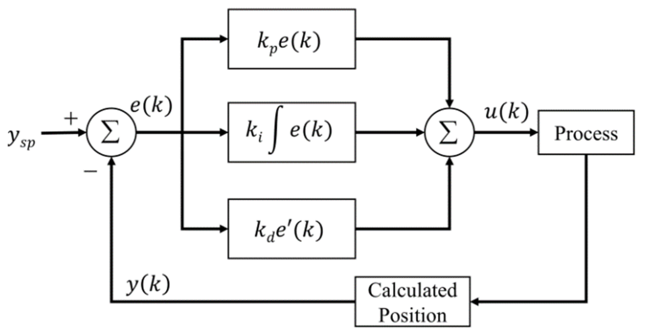
2.1. Conventional PID Controller

The operation of a conventional closed-loop PID controller in applying a WMR tracking system is expressed as Equations (1)–(3), and the system architecture is shown in Figure 1. Where ysp: the set point of the controller, e(k): the error of the sensing position and set point, e′(k): the error variation of two consecutive moments, kp: the proportional gain parameter, ki: the integral gain parameter, kd: the derivative gain parameter, u(k): the output of PID controller operation. Process block: the voltage of the right and left motors is controlled by the value of u(k) to control the speed difference. Calculated Position block: the position y(k) of WMR is calculated and fed back to the input end (Σ) and compared with the controller set point ysp for the PID controller to control the position error. Expressed as Equation (3), kp, ki,and kd are three important gain parameters of the PID controller, and appropriate tuning of the values is closely bound with the control effectiveness of the PID controller [17,18].
e ( k ) = y s p y ( k )
e ( k ) = e ( k ) e ( k 1 )
u ( k ) = k p e ( k ) + k i e ( k ) + k d e ( k )

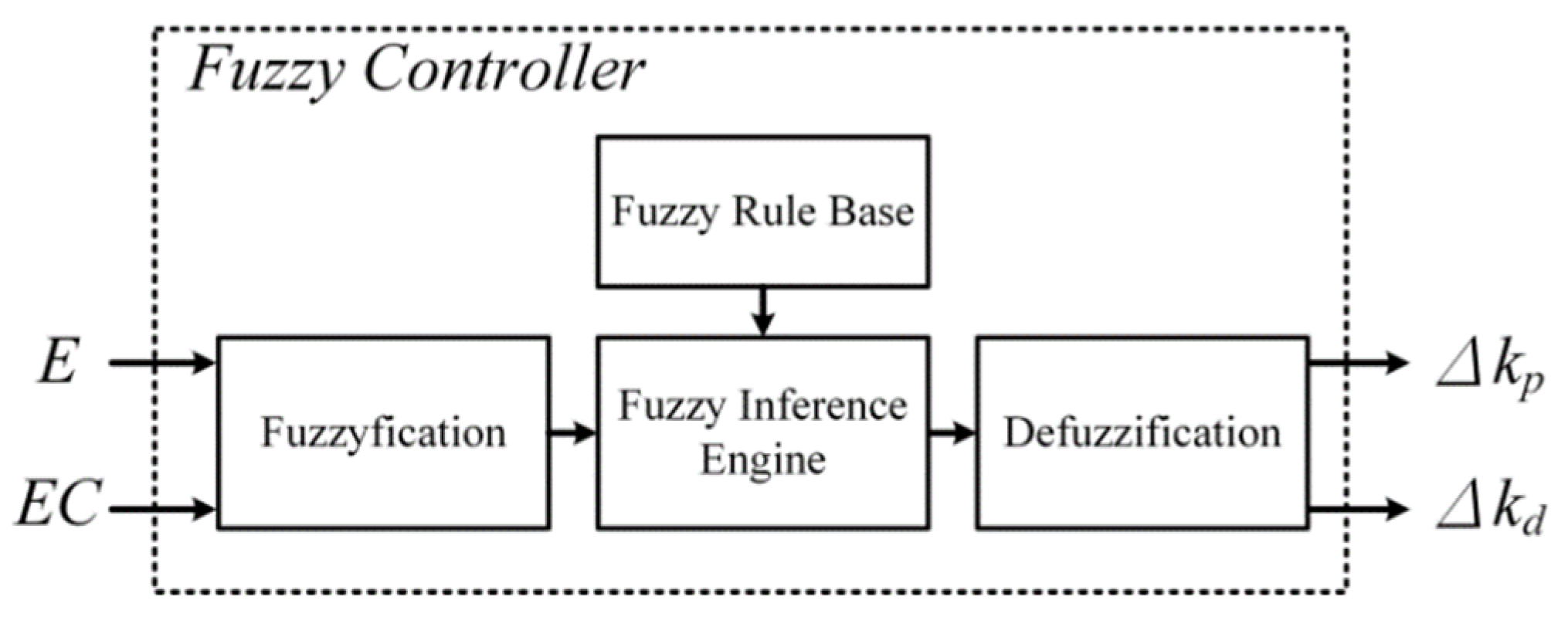
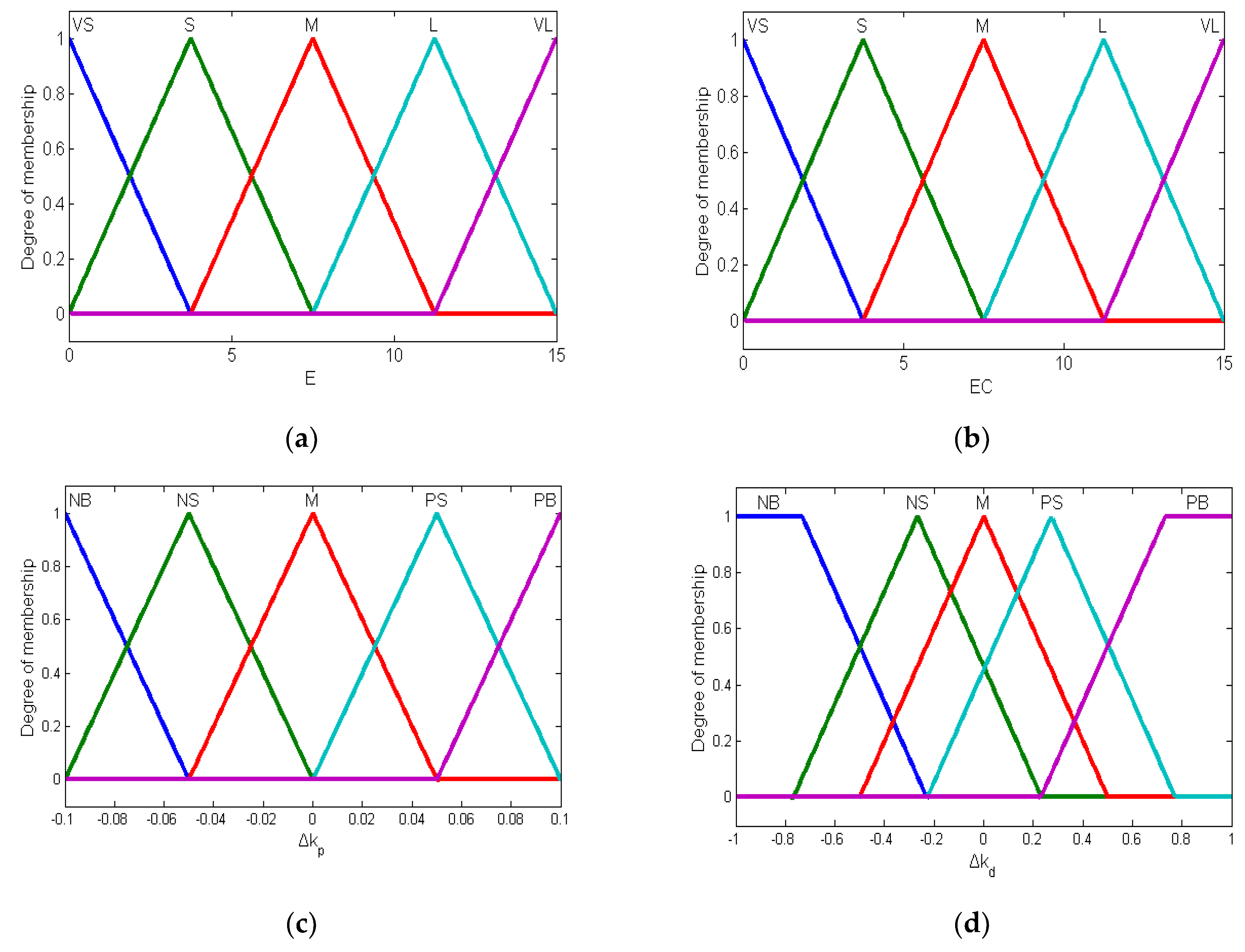
2.2. Fuzzy Controller

The system architecture of the fuzzy controller is shown in Figure 2. The operation mode is approximately divided into five parts: (1) define input/output variable; (2) fuzzification; (3) create a knowledge base of rules; (4) fuzzy inference; (5) defuzzification. In Figure 2, input parameters E and EC of the fuzzy controller are defined, which are obtained by normalizing the e(k) and e′(k) of the PID controller (Figure 1). Afterward, input parameters E and EC are converted into semantic values by the fuzzification program. The corresponding semantic fuzzy output is generated after fuzzy inference of the fuzzy rule base, as designed by expertise. Finally, the semantic fuzzy output is converted into the crisp output of the fuzzy controller by the operational program of defuzzification for the PID controller to tune gain parameters (Δkp, Δkd) [19,20].

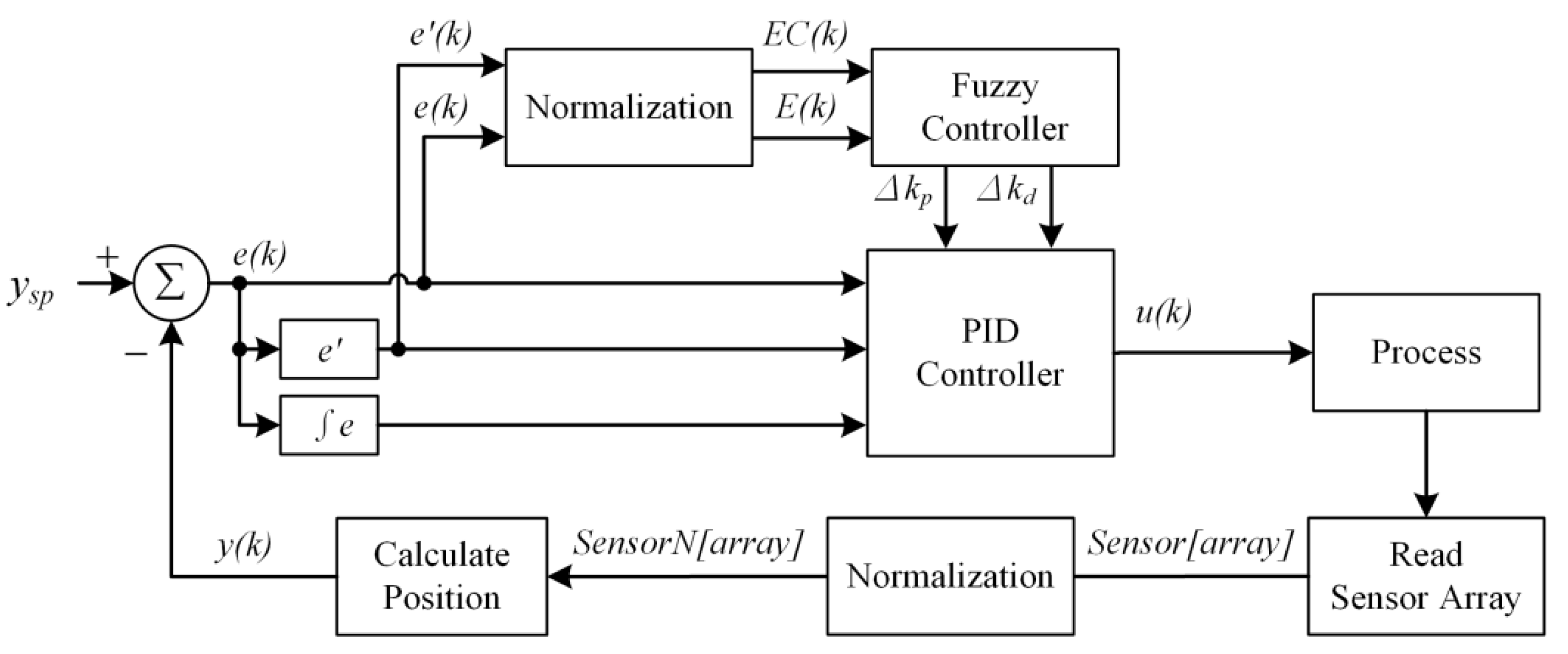
2.3. Fuzzy-PID Controller

As stated above, the Fuzzy-PID used in this study was combined with fuzzy control and a conventional PID controller to remedy the defect of using fixed gain parameters in the conventional PID controller and render control more accurate and the system steadier. The system architecture is shown in Figure 3. In terms of the system workflow and principle design, the position error amount e(k) and error variation e′(k), as obtained by comparing the detected value of the sensor array with ysp after normalization, and position calculation were used as the input parameters of the PID controller. However, in terms of the fuzzy controller, the original e(k) and e′(k) are normalized to obtain the corresponding E(k) and EC(k) as the input parameters. After a series of fuzzification, fuzzy inference, and defuzzification processes, gain parameter modulations Δkp and Δkd are obtained to tune PID controller gain parameters kp and kd. Finally, the PID controller exports u(k) to the process block according to the tuned kp and kd as the basis of motor voltage modulation and left-right speed difference control.

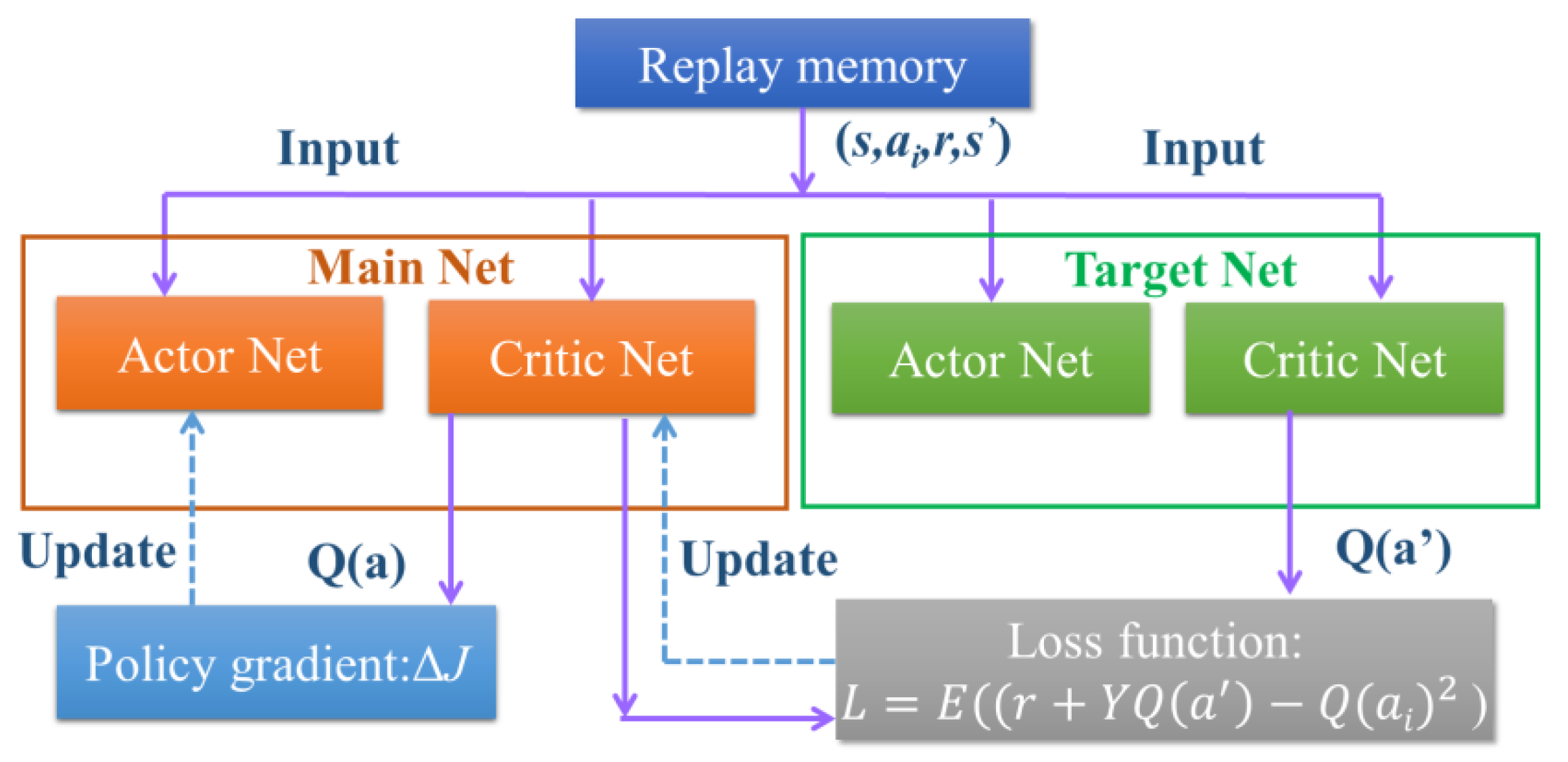
2.4. Deep Reinforcement Learning(DRL)
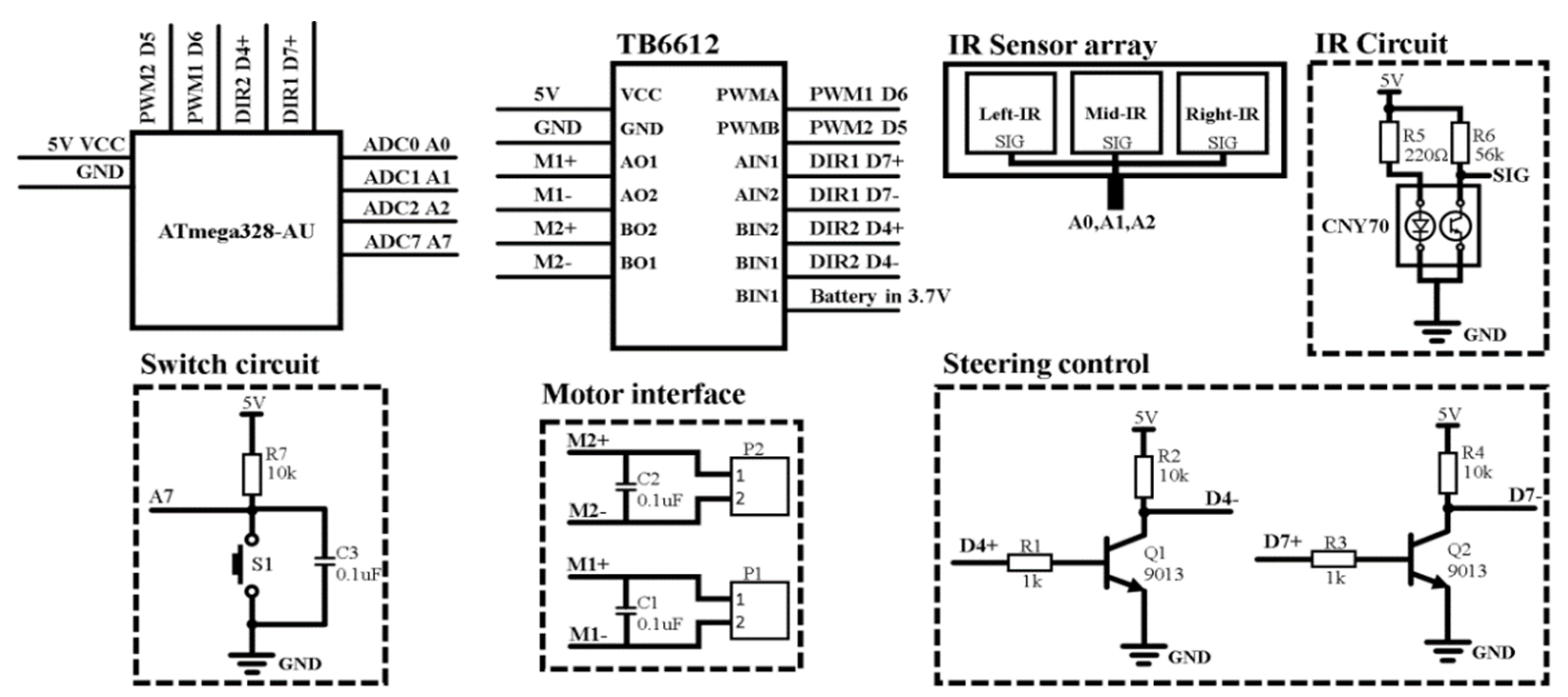
Reinforcement learning is an important branch of machine learning. Reinforcement learning is based on the Markov decision process and is suitable for controlling individuals who act autonomously in the environment. Through the interaction process between the intelligent body and the environment, it continuously learns and optimizes the action selection of the intelligent body in the current state so as to achieve a good control effect on the intelligent body itself. After the agent in reinforcement learning makes a decision, it will generate action and apply this action to the environment. If the environment gives the agent an instant reward value, the reward value will indicate that the agent is performing the action and changing the environment. The degree of satisfaction for the environment after is the state [21]. The basic structure of reinforcement learning is shown in Figure 4.
This study considers that the input space and output space of the motion control of the tracking unmanned vehicle are continuous, so in this study, the depth under the Actor-Critic (AC) framework suitable for continuous input and output space is adopted. Deterministic policy gradient (DPG) algorithm is the process framework of the AC algorithm shown in Figure 5 [22].
In the DPG algorithm, the samples in the training process are stored in the replay memory in turn, and a certain amount of mini batch samples are randomly selected for training. ActorNet accepts sample state S t drawn from replay memory. According to the strategy function a = π ( s / θ π ) , the optimal action a t considered by the strategy function at this moment is obtained, The action acts on the environment to obtain the next moment state S t + 1 , and CriticNet accepts the current moment state S t and action a t at the same time, and inputs the next moment state S t + 1 into the target network TargetNet to obtain the target expected value r + Q ( S t + 1 , a t + 1 / θ Q ) , The squared difference between the target expected value and the current expected value is the loss function of CriticNet, which is used to update the CriticNet network, while the ActorNet network relies on r + Q ( S t + 1 , a t + 1 / θ Q ) to update the parameters with respect to the expected gradient of θ π . The framework of the DPG algorithm is shown in Figure 6 [23].
There are three very important concepts in reinforcement learning: state, action, and action reward. These three concepts directly affect the final learning effect. The action in this study is designed as the rotational speed, which is also the network output of the neural network controller. In the motion control problem of the WMR system, according to the existing experience and knowledge, the target state and the current state of the WMR system must be known when controlling the tracking unmanned vehicle. So in this study, the state of reinforcement learning problem is defined as the difference between the target state and the current state [24].
At the same time, to improve the generalization performance of the controller and make the controller adapt to the control of different trajectory targets and states, in this study, the difference between the target state and the current state is normalized, and the difference between the difference and the target value is normalized. The ratio serves as the state ratio, which is the input to the neural network, as shown in Equation (4).
S = G C G
In Equation (4), S is the state ratio of the WMR system, G is the target state value of the WMR system, and C is the current state value of the WMR system. In the process of reward function design, considering that the closer the current state value of the tracking unmanned vehicle is to the target state value, the greater the reward feedback received by the neural network, the reward function is designed as a negative exponential function of the state ratio S. When the tracking unmanned self-propelled vehicle reaches the target state value, the neural network gets the maximum feedback value, as shown in Equation (5).
R = k e | S |
In Equation (5), R is the reward feedback value of the tracking unmanned vehicle, and k is the feedback coefficient [25].

2.5. MBot Robot

This study used the mBot robot as the test platform for a Fuzzy-PID controller in the WMR tracking system. The main hardware architecture is shown in Figure 7. Atmega328-AU is the Atmeal AVR series 8-bit microcontroller and the arithmetic and control core of this system. The motor driver IC is TB6612, which can drive a 15 V/1.2 A DC motor. The IR array is changed to 3 CNY70 circuit modules, and each contains one infrared transmitter and one phototransistor. The SIG voltage signal change resulting from the variation of the phototransistor with infrared reflection is read to accurately determine the real-time position of the mBot robot on the tracking path. The forward/reverse rotation of the motor and left-right speed difference was controlled by the motor driver IC (TB6612) [26].

3. Experimental Methods

The experimental design and adjustment processes of gain parameters Δkp and Δkd are shown in Figure 8. When the control program is started, the sensor reading is normalized and stored in the SensorN array. The Position data are obtained by the weighting operation of the value of the SensorN array. The e(k) and e′(k) are determined from PID control Equations (1) and (2) and normalized to obtain E(k) and EC(k) as the input parameters of the fuzzy control system, as designed by the Fuzzy Logic Toolbox of Matlab. There are 256 IF-THEN discriminant sentences listed, where the Δkp and Δkd are determined for compensation modulation of the gain parameters of the PID controller. In this experiment, it is noteworthy that, to reduce the amount of CPU calculation and save memory space, the mBot vehicle body framework, the location of the three sensors. The tracking path coordinate settings have high symmetry. Therefore, for the fuzzy controller in this experiment, the positive and negative values of e(k) and e′(k) are disregarded. In contrast, the absolute values |e(k)| and |e′(k)| are directly used as the input parameters of normalization. However, the e(k) and e′(k) are kept as input parameters for the PID controller to decide the rightward or leftward deviation of mBot.
According to the experimental process in Figure 8, the normalization, position calculation, tracking path regression, Fuzzy-PID gain parameter system design, and tracking path test design are briefly described as follows.

3.1. Normalization

As the process and characteristics of each CNY70 sensor are slightly different, the read sensor parameters are more or less different. The normalization operation is expressed as Equations (6) and (7), which improve the characteristic difference of the different sensors, and the range of experimental parameters e(k) and e′(k) is modulated. Where Xin: input value of the normalization operation, Yout: output value of the normalization operation, Xmin(Xmax): the minimum set value (maximum value) of Xin in this experiment, Ymin(Ymax): the minimum set value (maximum value) of Yout in this experiment [27].
Y out = Y [ X in , X min , X max , Y min , Y max ]
Y out = { Y min + ( Y max Y min X max X min ) × ( X in X min ) , i f   X min < X in < X max Y min , i f   X in X min Y max , i f   X in X max

3.2. Position Calculation

The position calculation gives the position of the IR Array in relation to the path during robot tracking, and the controller operation corrects the real-time tracking path. The detailed computing mode is expressed as the following pseudocode A. Step 1: the voltage value of each sensor of the IR Array is read and stored in the sensor array from left to right. Step 2: the sensor value of the sensor array is stored in the sensor N array after normalization operations. The sensor normalization parameter is sensor N [Sensor,150,800,01000], meaning when the sensor value is smaller than 150, it is normalized to 0; if it is greater than 800, it is normalized to 1000; while the other values are normalized by Equation (7), to reduce the effect of the site and environment on the sensor reading. Step 3: the operation parameter is initialized. Step 4: the sensor values are multiplied by their respective weights, added by cycle, the total value sum parameter is obtained, and all the sensor values are added up to obtain the weighted parameter. Step 5: the sum is divided by the weighted value, and the position parameter value of the IR array in relation to path location is obtained. In the IR array setting with three sensors, the central location of the path is set as 1000, and the position value corresponding to the sensing array from the right to the left of the path is 0 to 2000.
Pseudo code A:
  • Read Sensor Array voltage from Sensor[array] = [Left-IR, Mid-IR, Right-IR]
  • Normalize Sensor Output SensorN[array]
  • Count = 0, Sum = 0, Weighted = 0
  • WHILE(Count < 3)
      Sum = Sum + (SensorN[Count] × Count × 1000)
      Weighted = Weighted + SensorN[Count]
      Count = Count + 1
     END WHILE
  • Position = Sum/Weighted

3.3. Regression of Tracking Path

When a robot is executing a tracking task, it often deviates from the path due to sharp turns, which cannot be modified instantly. Thus, it fails to retrieve the correct direction. Therefore, an algorithm is required to judge the deviated path direction in order that the robot can make corrections according to the right direction. The detailed calculation is expressed as the following pseudo-code B. Step 1: judge whether the position data is 0 or not (value 0 means the sensor has left the path). Step 2: if the position data is 0, judge whether or not the previous sensing position smaller than 1000 is true; if it is true, the position value is set as 0. Step 3: if it is not true, the position value is set as 2000. Step 4: if Step 1 is not true, the position operation value of the sensor in path tracking is updated to the last sensed position value.
Pseudo code B:
  • IF Position is 0 value THEN
  • IF LastPosition < 1000 THEN
      Position = 0
  • ELSE IF LastPosition > 1000 THEN
      Position = 2000
     END IF
  • ELSE THEN
    LastPosition = Position
     END IF

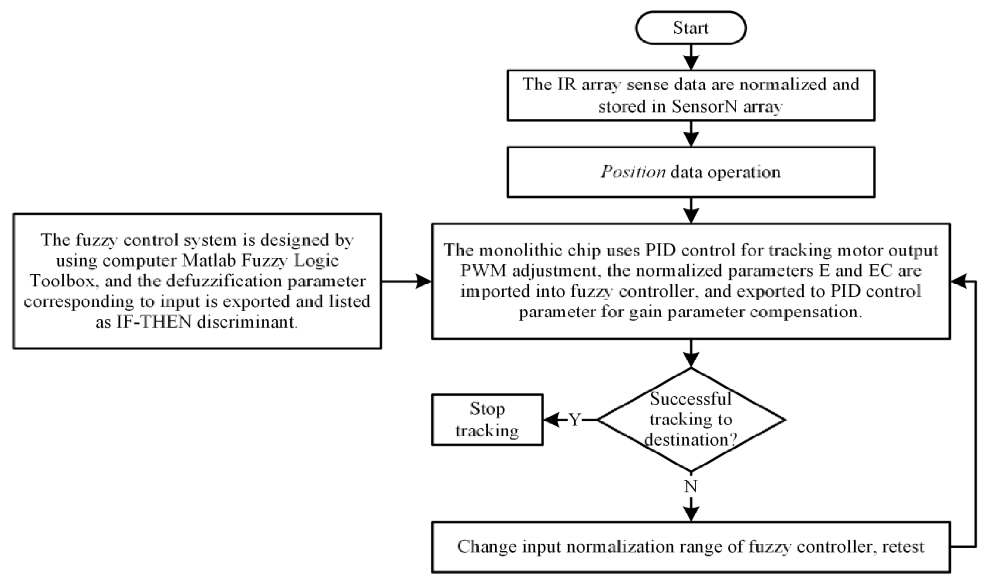
3.4. Fuzzy-PID Gain Parameter System Design

The conventional PID controller uses fixed gain parameters kp, ki and kd, as it is difficult to optimize the complex tracking site design, control system stability, and maximum overshoot of the system. In order to solve this problem, this paper uses fuzzy control to modulate the gain parameters of the PID controller. As gain parameters kp and kd vary with the data, it implements better control performance. Many studies have discussed using a fuzzy controller for operation after the PID controller calculates the output, adjusts the gain parameters of the PID controller, or directly modifies the outputs of the PID controller to improve the adaptation of the conventional PID controller [28,29]. While these methods have a significant effect, a lot of operation and memory space is required in practical application; thus, the cost is relatively high. Therefore, as mentioned above, this paper proposes simple system architecture and uses fuzzy control to modulate the gain parameters, which reduces the number of chip operations and saves memory space [30].
Figure 9 shows the design of the input/output membership function for the fuzzy controller of this paper. Figure 9a shows the regularization parameter E(k) of position error amount e(k); Figure 9b shows the regularization parameter EC(k) of position error variation e′(k), and both are designed by using five typical membership functions. The linguistic variables are VS: very small, S: small, M: medium, L: large, VL: very large. The interval of linguistic variables is 0 to 15. Figure 9c,d show the proportional gain modulation parameter Δkp and derivative gain modulation parameter Δkd of the PID controller, respectively. The linguistic variables are NB: negative big, NS: negative small, M: medium, PS: positive small, and PB: positive big. The range of the Δkp fuzzy interval is set as −0.1 to 0.1, while the range of the Δkd fuzzy interval is set as −1 to 1, and this modulation range is sufficient to deal with most disturbances.
According to the gain adjustment experience of the PID controller, the rule list of the fuzzy controller is created. When E(k) is large and EC(k) is small, the distance to the set point is long, and modulation is slow; thus, the gain parameter must be increased. When E(k) is medium and EC(k) is medium, the distance to the set point is short, and the adjustment is a little fast; thus, the gain parameter must be slightly reduced to prevent excessive system overshoot. When E(k) is small, the error to the set point is small, and the gain parameter must be minimized. Table 1 shows the complete fuzzy rule base, as established according to the aforesaid rules.
In Figure 10a,b the fuzzification process attaining compensation parameters Δkp and Δkd of the defuzzification surfaces. As shown in the figure, we found Δkp of the surface to be steeper, and Δkd is relatively smooth. Its designed to reduce kd gain the amplitude of fluctuation, and kp gain has the large adjustment range of minor errors, can improve the response speed of large adjustments. Defuzzification uses discrete center of gravity, expressed as Equation (8), where n represents the output total quantized number, yi represents No. i quantized value, and μC(yi) represents the membership value of yi in fuzzy set C.
y * = i = 1 n μ C ( y i ) y i i = 1 n μ C ( y i )

3.5. Design of Tracking Experiment

To determine the performance difference between the conventional PID controller and Fuzzy-PID controller, this experiment uses a white background, a black path, and a finish line orthogonal site, as shown in Figure 11a. At the same time, the tracking test of the step response and the function are expressed as Equation (9). At time 200 ms, the system set point ysp is changed from 1000 to 1600 in order to test the stability of Ps of the control system and maximum overshoot percentage (MO) [31].
y s p = { 1000 , t < 200   ms 1600 , t 200   ms
In addition, the design of fuzzy control is adjusted according to the test results of the step responses to create a Fuzzy-PID parameter gain control system better than the conventional PID controller. Finally, as shown in Figure 11b, an S-shaped curve, a common curve site tracking task, is used to compare control effectiveness and discuss tracking completion time and stability Ps.
The definition of the control system stability check indicator Ps is expressed as Equation (10), where a smaller value represents higher system stability. Where n: the total number of read data, |e(k)|: the signed magnitude arithmetic of No. k error amount e(k), ysp: the tracking set point of the system, and ysp = 1000 in this experiment. In addition, the maximum overshoot percentage (MO) of this system is defined as Equation (11). Where yextreme: the sensing extreme point with maximum error amount to system set point ysp, ymax: the maximum position point of the system, and ymax = 2000 in this experiment
P s = 1 n k = 1 n | e ( k ) |
M O = | y e x t r e m e y s p y m a x y s p | × 100 %

4. Results and Discussion

In this study, the DRL-Fuzzy-PID control method was used for related experiments and simulations where the purpose was to develop an unmanned tracking bicycle with intelligent computing. The experiment was carried out by driving the bicycle, and the tracking part was to limit the same path every time for comparison, and the iterative calculation method was used to find the best convergence time. Therefore, the battery saturation of the experimental bicycle is the same as the capacities are all the same, and the changes in obstacles and trajectories must be the same for comparison. In addition, in the process of conducting experiments under the limited conditions of this study, such as changes and uncertainties of experimental conditions such as external environment light and road conditions, it is a problem worthy of an in-depth discussion in the DRL-Fuzzy-PID control system. This research has successfully developed a self-propelled vehicle with intelligent computing. In the future, it can connect multiple vehicles for Internet of Things cloud computing to construct a relatively large intelligent self-propelled vehicle system, which can be applied to unmanned trucks in automated factories, or it is the application of intelligent Internet of things bicycles and other applications of automatic warehousing.

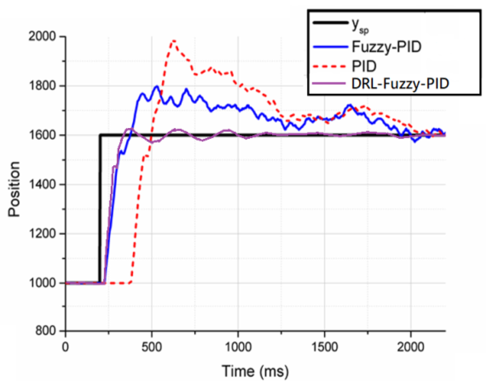
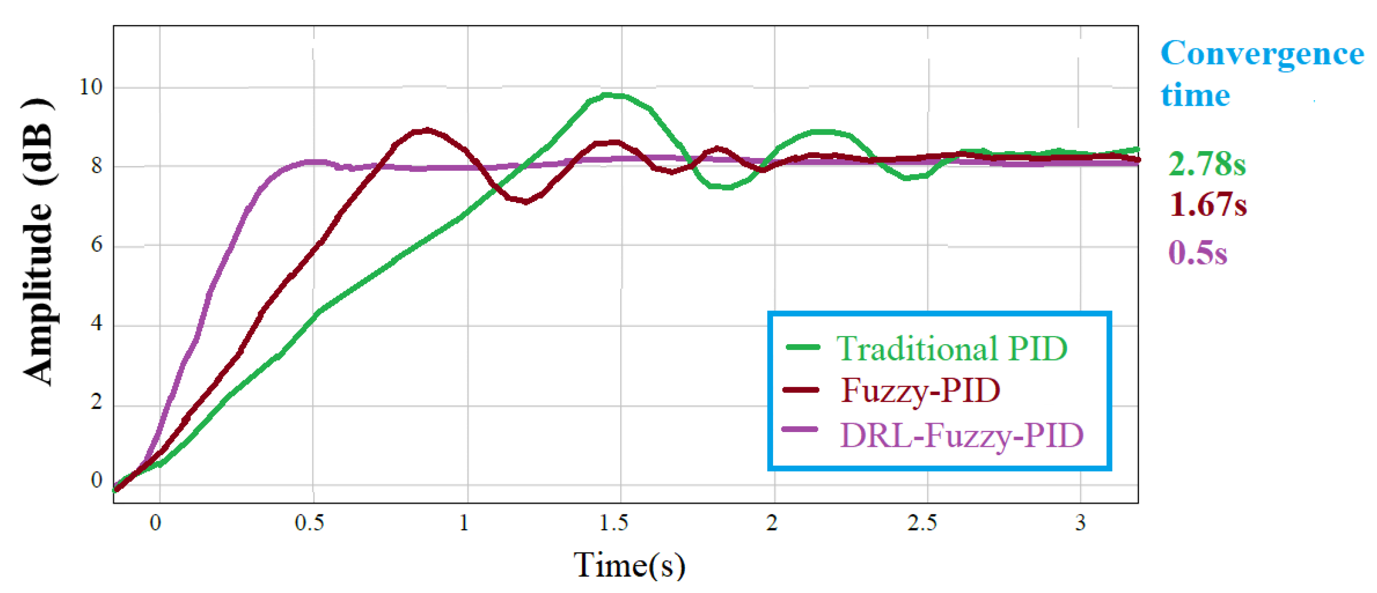
4.1. Comparison of DRL-Fuzzy PID, Fuzzy PID and Traditional PID Control in the Step Response of mBot

This study used a straight black path and Equation (9) to test the performances of the conventional PID, Fuzzy-PID, and DRL-Fuzzy-PID controller in the one-step function response to compare the optimization of the control systems. To fully demonstrate the performance difference among PID, Fuzzy-PID and DRL-Fuzzy-PID controllers, the parameter designs in this step response test are identical, as shown in Table 2. Speedmax: the maximal output of motor PWM control, if the PWM value is 255, the output voltage is 5 V, and the other PID control gain parameters are the better values found in this experiment. It is known that the DRL-Fuzzy-PID controller adjusts the input parameters by normalization, and the range is related to the response speed and modulation of DRL-Fuzzy-PID modulation, which significantly influences control effectiveness. As the system set point ysp = 1000 in this experiment, and the system tracking range is 0~2000, the tracking error amount e(k) is −1000 ≤ e(k) ≤ 1000. Therefore, based on system symmetry and the consideration of shortening CPU computing time and saving memory space, the normalization operation of e(k) only takes the absolute value |e(k)| as the operation parameter. When parameter en(k) is obtained, the input parameter E(k) of the fuzzy controller is obtained by the normalization operations of parameter en(k). The overall operation sequence is e(k)− > |e(k)|− > en(k)− > E(k), expressed as E(k)[|e(k)|, enmin, enmax, Emin, Emax], where enmin, enmax, Emin and Emax represent the minimum and maximum set values of en and E in this experiment. Similarly, the normalization operation of e′(k) refers to e(k), expressed as EC(k)[|e′(k)|, en′min, en′max, ECmin, ECmax].
As stated above, in the step response experiment, the normalization operation parameter settings for e(k) and e′(k) are E(k)[|e(k)|,0200,0,15] and EC(k) [|e′(k)|,0,70,0,15], as shown in Table 2. Figure 11, Figure 12 and Figure 13 and Table 3 show the results of the conventional PID, Fuzzy-PID, and DRL-Fuzzy-PID controller after compensation calculation of gain parameters kp and kd. Figure 13 shows the relationship between the compensation modulation and tracking time of kp and kd. For the experimental part of parameter compensation adjustment, we set PID initial value kp is 0.16 and kd is 1.0. Since the robot is initially positioned exactly at the center point 1000, thus, E and EC will be close to zero, kp and kd received the influence of the compensation parameters Δkp and Δkd, it will be reduced to low points. Due to 200 ms the step response, the system needs to adjust the compensation greatly so that the gain parameters kp and kd rise to 0.24 and 0.17. After constant adjustment of the parameters, the gain parameters are close to stabilizing. As can be seen in Figure 13, we use the step response experiment as an example. The FPID can correct the parameters faster and reach stability at 1900 ms. Table 3 shows the experimental results of the control effectiveness of tracking stability Ps and M.O. According to the experimental data, the system stability Ps of the DRL-Fuzzy-PID controller is lower than that of the PID controller by 83.4, and the performance of M.O. is reduced by 47.5%. The DRL-Fuzzy-PID control system designed in this paper has much better control effectiveness than the conventional PID controller.

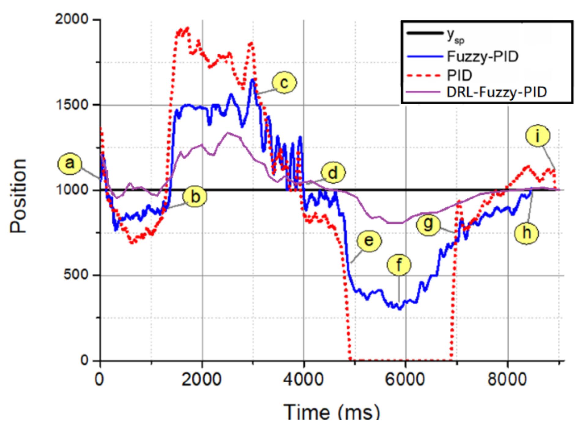
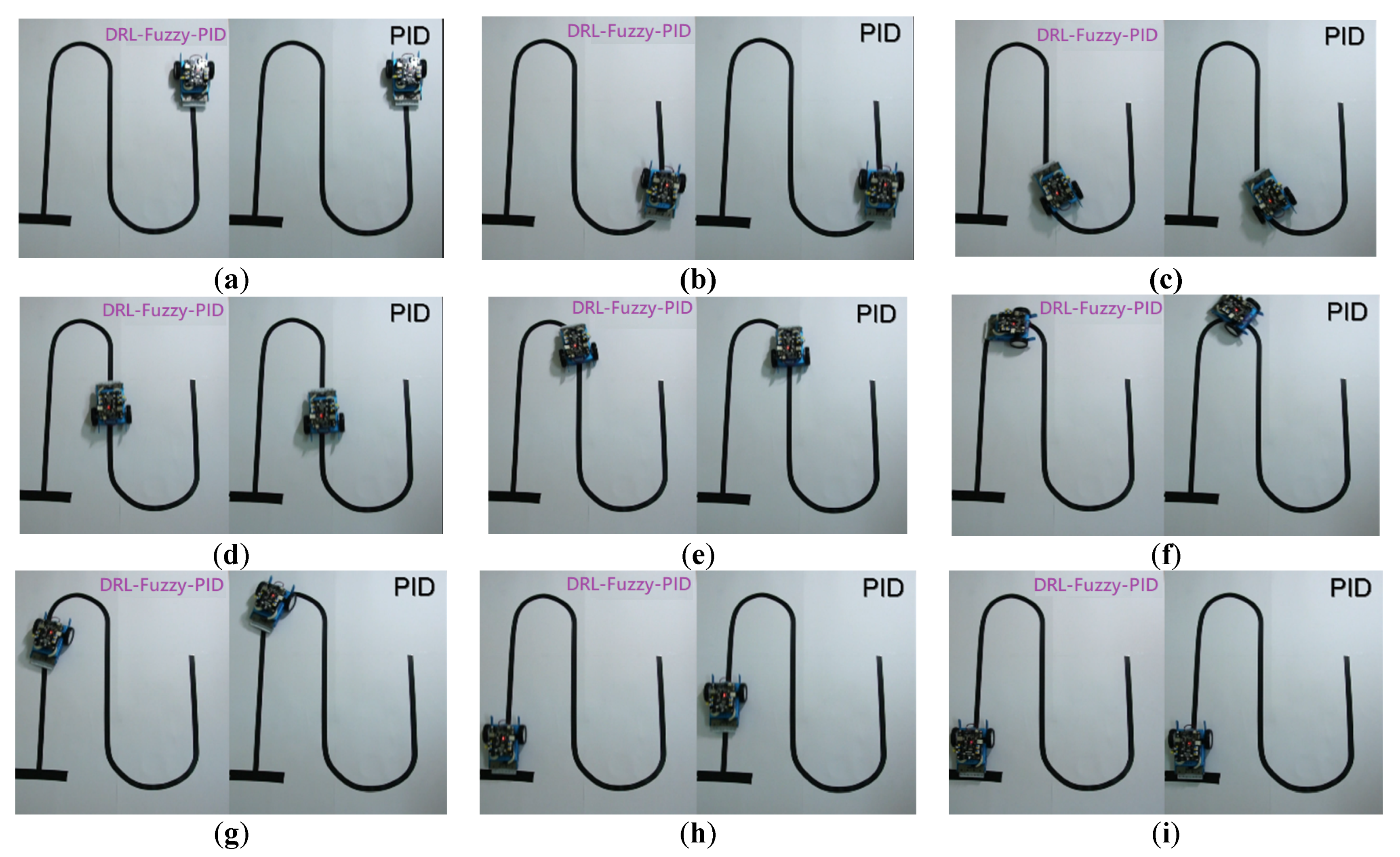
4.2. Comparison of DRL-Fuzzy PID, Fuzzy PID Control and Traditional PID Control in mBot Field Tracking

The field tracking performance comparison of conventional PID, Fuzzy-PID, and DRL-Fuzzy PID controller is shown in Table 4, which follows the parameter design shown in Table 2. After the normalization operation of e(k) and e′(k) in this experiment, the input parameters E(k)[|e(k)|,0200,0,15] and EC(k)[|e′(k)|,0,70,0,15] of the Fuzzy-PID and DRL-Fuzzy-PID controller are obtained, and the performances in the straight and curved tracking test for mBot are better than the PID controller. The site tracking tasks are compared in Figure 14. Table 5 shows the performance in tracking stability Ps, maximum overshoot M.O., and tracking time. The results show that when the system set point ysp is set as 1000 for a tracking task, the system stability Ps of the Fuzzy-PID and DRL-Fuzzy PID is lower than that of the PID controller by 15.2%, and the performance of M.O. is reduced by 35.6%. The correction time of PID for an excessive angle accounts for 22% of the overall tracking time, while the DRL-Fuzzy-PID tracking does not leave the line. According to the tracking path in Figure 15, while the DRL-Fuzzy-PID system sometimes corrects its deficiencies, it is much more optimized than the PID controller (e.g., mark 2 to 3 and 5 to 7). In addition, the overall tracking time of the DRL-Fuzzy-PID is shorter than that of the PID controller by 524 ms; thus, the demand for time is reduced by about 6.78%.
However, DRL-Fuzzy-PID, Fuzzy-PID, and PID present different path tracking effects, as shown in Figure 15 and explained with the marks in Figure 14.
Figure 16 shows the relationship between the compensation modulation and tracking time of kp and kd. For the experimental part of parameter compensation adjustment, we set PID initial value kp as 0.17 and kd as 1.0. Gain parameters, kp and kd, increased to 0.3 and 1.73, respectively, as the system must make a significant adjustment to compensate at the bend; but decrease to 0.04 and 0.27 in straight line mode.

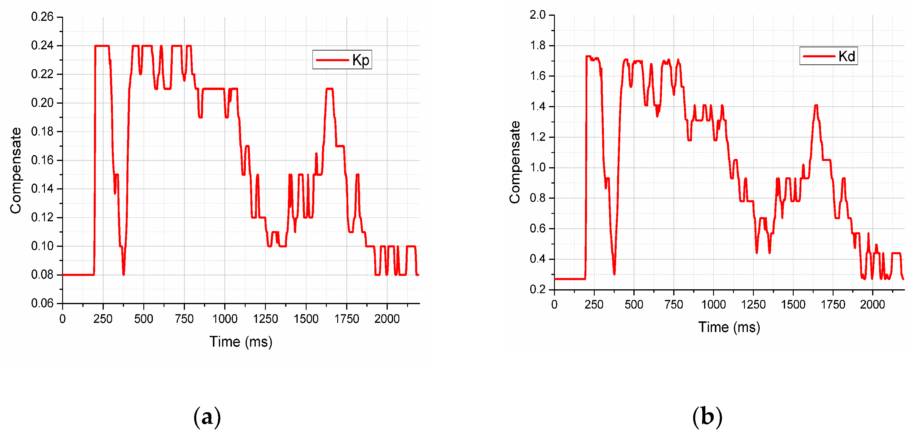
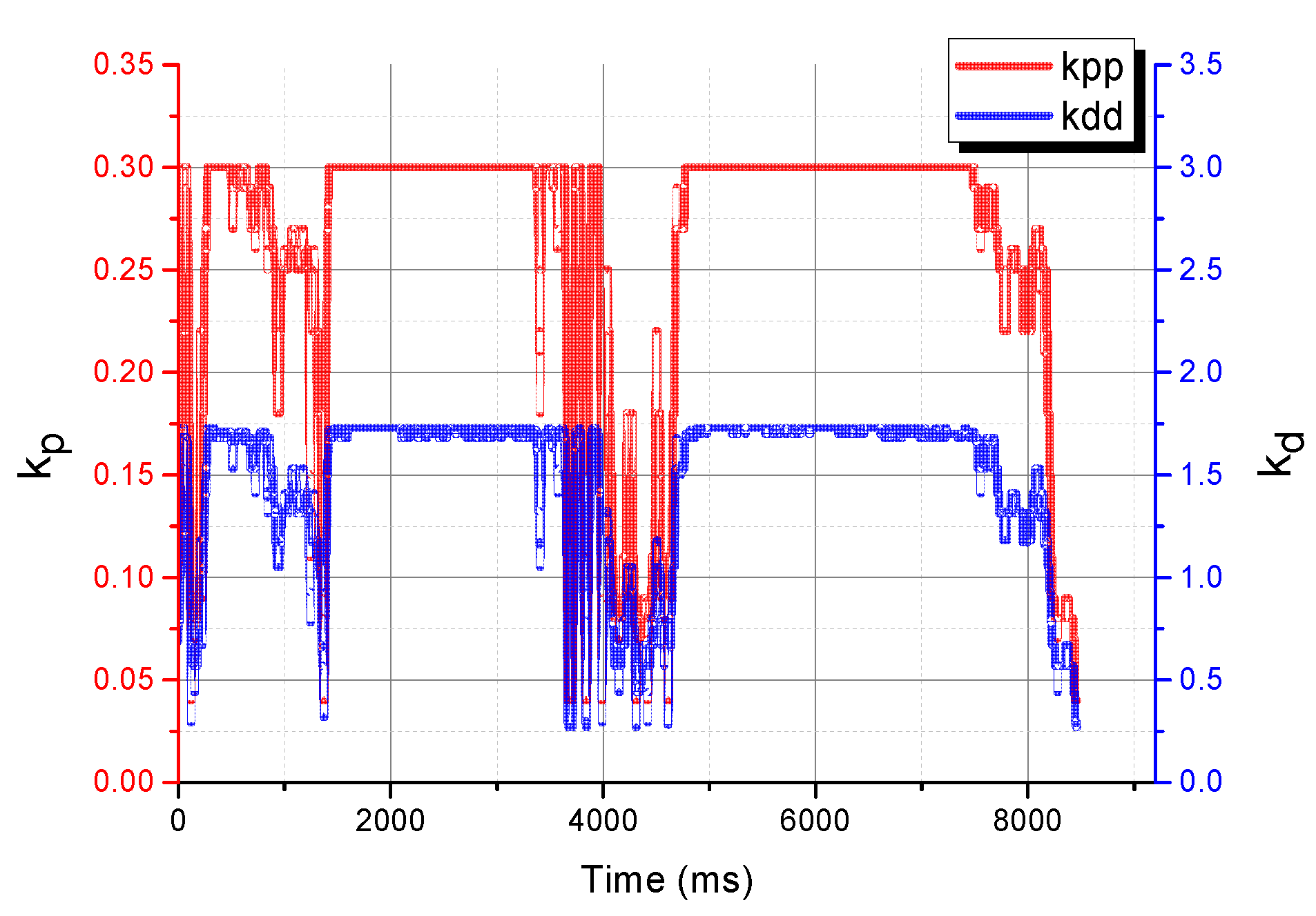
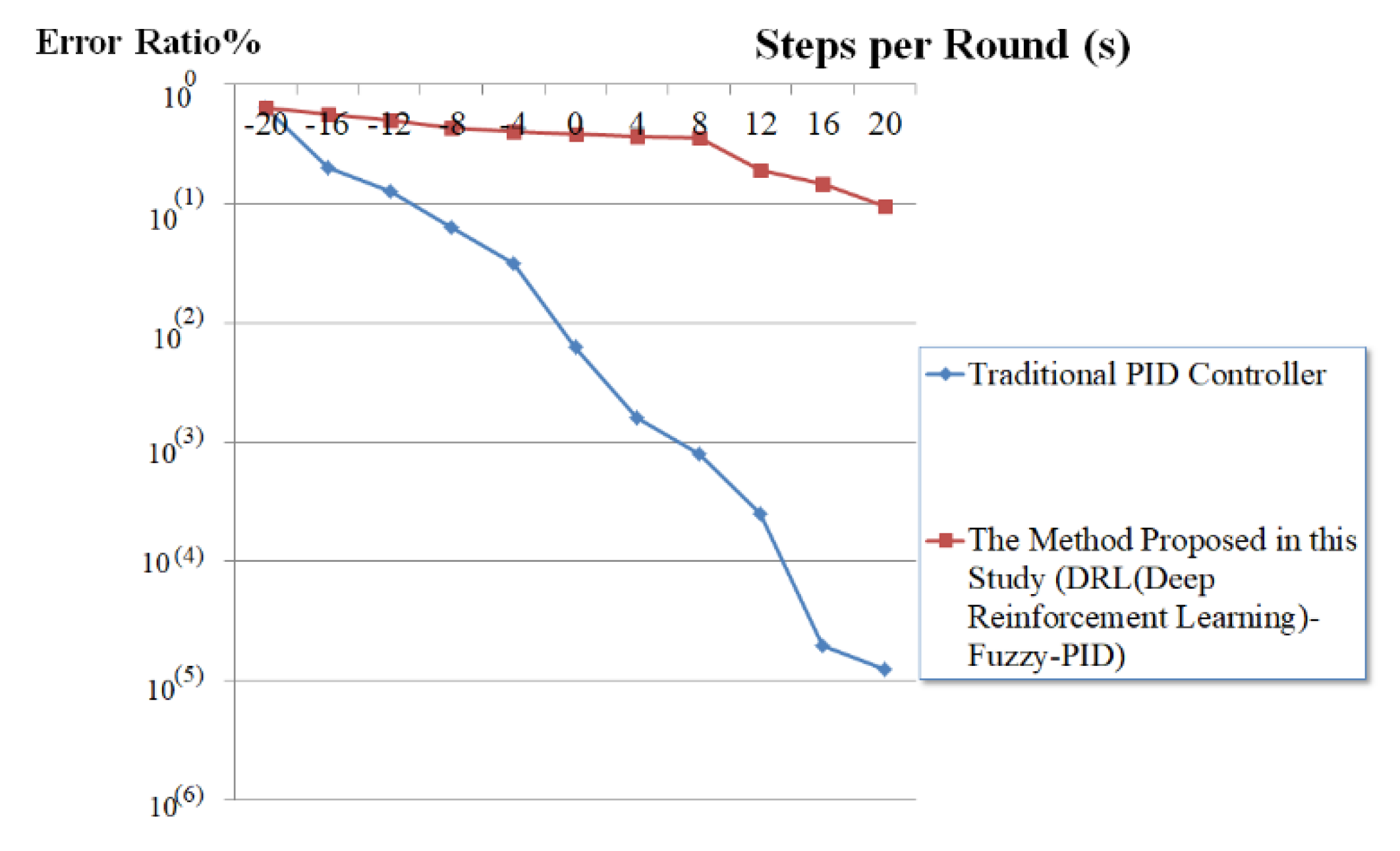
4.3. Experiments and Discussions Based on Deep Reinforcement Learning(DRL)

In the final experiment of this research, the trajectory control algorithm based on deep learning uses a neural network as the motion controller. The neural network has a strong mathematical mapping ability and can describe the controller mathematically. Compared with the traditional PID control algorithm, the DRL-Fuzzy-PID control algorithm based on deep learning proposed in this study can save the experience-dependent and time-consuming manual parameter adjustment process (Fuzzy defines the attribution function program). To a certain extent, the development difficulty of the DRL-Fuzzy-PID control algorithm is reduced. The author’s previous related research proposes a control algorithm using a supervised learning neural network for DRL-Fuzzy-PID training. Compared with the supervised learning training method, the algorithm proposed in this study saves the collection process of training samples and has more obvious advantages. This study analyzes the motion characteristics of the tracking unmanned vehicle and the characteristics of common reinforcement learning algorithms. Combined with its dynamic characteristics analysis and design environment state space, and analysis of action space and reward conditions, intelligent deep learning control and environment interactively generate training samples and train the network to achieve motion control of tracking unmanned vehicles.
Taking the controller test training as an example, during the test training process, to improve the generalization ability of the controller and reduce the complexity of the state design, the training of this round was stopped if the target state was not set during the training process of each round. If it is judged that the target state is reached in each round of training, the state that needs to be judged is complex and in the form of floating-point numbers. Taking the height controller as an example, when judging to reach the target height state, it is necessary to judge that the height is near the target value, and the speed and acceleration are near the zero value. Therefore, in the training process of the DRL-Fuzzy-PID controller in this study, the training time was appropriately extended for each round. Due to the existence of the reward function, the controller will gradually stabilize near the target value to obtain the maximum return, thereby achieving a stable controller. Training avoids the problem of state judgment and enhances the controller’s generalization ability.
After a series of tests and assessments, during the controller test training process, the controller is trained with 100 steps per round and 300 rounds of rounds to obtain a converged controller. The experimental parameter settings during the controller training process are shown in Table 6.
The trained controller has a good tracking effect in terms of state tracking. Figure 17 shows the tracking control error diagram of the reinforcement learning controller. The curve in the figure shows the error change of the tracking process. It can be seen from Figure 17 that the error value of the algorithm proposed in this study converges to within 5% during the second session and training.
The controller that was tested and trained had a good anti-interference ability. In the presence of interference, it only oscillated in the initial stage and then quickly returned to the steady state. Figure 18 is a graph comparing the frequency response curves of the controller proposed in this study (DRL-Fuzzy-PID), Fuzzy-PID and traditional PID control after training. (The setting value is 8 dB, and the optimal convergence time is 0.5 s (DRL-Fuzzy-PID)).
Through the analysis and comparison, it can be seen that the deep reinforcement learning control has better control performance. This research proposes a new control scheme, introduces the reinforcement learning method, analyzes the environmental state of the controlled object when it moves, and designs the corresponding penalty function—a motion control solution for tracking bicycles based on deep reinforcement learning. Through simulation experiments, it is verified that the method can well complete the motion control of the unmanned boat and has a better control effect than the traditional PID algorithm under the same conditions. Using the adjustment calculation and adaptive changes of the gradient in reinforcement learning to improve the Fuzzy-PID algorithm in (1) fast response, (2) correction of a steady-state error, and (3) avoid artificial intuition error judgment, the above three points have good compensation, and the correction function can be verified from the experiments. Among the three algorithms discussed in this study, the DRL-Fuzzy-PID algorithm has the shortest convergence time ratio, the fastest rise time, and the smallest steady-state error.

5. Conclusions and Future Work

This research proposes a DRL-Fuzzy-PID controller with gain parameter compensation architecture based on deep reinforcement learning, which reduces the CPU computing load of the microcontroller and saves memory space. The simulated WMR tracking test results in the experiments in this study show that the deep reinforcement learning fuzzy controller can effectively compensate the parameter values when the PID controller parameter settings cannot be corrected immediately. Therefore, DRL-Fuzzy-PID is about 238 ms faster than PID and starts to correct when testing for step response, reaching the stable point earlier. In the S-curve tracking task, the total time was reduced by about 36%. The DRL-Fuzzy-PID controller significantly improves the system stability and reduces the maximum overshoot percentage of the system. These experimental results show that the architecture of DRL-Fuzzy-PID is feasible, and its practical effect is very good. However, if the initial settings of PID gain parameters are not optimized, there is still a certain room for improvement in system tracking performance.
This research uses a deep reinforcement learning algorithm combined with the Fuzzy-PID control method to conduct experimental simulation and verification, understand the simplification of fuzzy control in nonlinear complexity, and add empirical rules. The biggest contribution of this paper is to improve the accuracy and efficiency of the overall WMR system and shorten the tracking time. This research paper takes the WMR system as the starting point, uses deep reinforcement learning technology, and combines the mathematical model of tracking bicycles to analyze and design the state space, action space, and environment reward. Through the interaction between the intelligent controller and the environment, training samples are generated, the network is trained, and the motion control of the WMR system is realized. It is verified by experimental simulation that the trained DRL-Fuzzy-PID controller can control the WMR system well and has certain advantages in stability and anti-interference ability compared with the traditional PID control algorithm.
In the future, this system can be combined with IoT cloud computing to establish two-way information collection and remote Fuzzy-PID controller settings to realize the establishment of system control on the cloud platform, a DRL-Fuzzy-PID control system, and IoT functions. In addition, the cooperative adaptive control of the entire WMR system can be improved. The multi-variable DRL-Fuzzy-PID cooperative control method can be used to adjust different trajectory lanes with good adaptability; that is, the multi-variable DRL-Fuzzy-PID control algorithm has good robustness to unstructured trajectories. In the future, this research can be used for the application and development of intelligent self-propelled vehicles. This research will develop towards the direction of multi-variable collaborative DRL-Fuzzy-PID control intelligent calculus in the future.

Author Contributions

Conceptualization, C.-T.L. and W.-T.S.; methodology, C.-T.L.; software, W.-T.S.; validation,; formal analysis, W.-T.S.; writing—original draft preparation, C.-T.L.; writing—review and editing, W.-T.S. All authors have read and agreed to the published version of the manuscript.

Funding

This research received no external funding.

Data Availability Statement

Data sharing does not apply to this article as no datasets were generated or analyzed during the current study.

Acknowledgments

This research was supported by the Department of Electronic Engineering at the National Quemoy University and the Department of Electrical Engineering at the National Chin-Yi University of Technology. The authors would like to thank the National Chin-Yi University of Technology, National Quemoy University for supporting this research.

Conflicts of Interest

The authors declare that they have no conflicts of interest to report regarding the present study.

References

  1. Möller, R.; Krzykawski, M.; Gerstmayr-Hillen, L.; Horst, M.; Fleer, D.; De Jong, J. Cleaning robot navigation using panoramic views and particle clouds as landmarks. Robot. Auton. Syst. 2013, 61, 1415–1439. [Google Scholar] [CrossRef]
  2. Backman, J.; Oksanen, T.; Visala, A. Navigation system for agricultural machines: Nonlinear model predictive path tracking. Comput. Electron. Agric. 2012, 82, 32–43. [Google Scholar] [CrossRef]
  3. Poongodi, C.; Premalatha, J.; Lalitha, K.; Vijay, A.D. Region based find and spray scheme for co-operative data communication in vehicular cyber-physical systems. Intell. Autom. Soft Comput. 2017, 23, 501–507. [Google Scholar]
  4. Matveev, A.S.; Hoy, M.C.; Savkin, A.V. The problem of boundary following by a unicycle-like robot with rigidly mounted sensors. Robot. Auton. Syst. 2013, 61, 312–327. [Google Scholar] [CrossRef]
  5. Santos, M.C.P.; Santana, L.V.; Brandão, A.S.; Sarcinelli-Filho, M.; Carelli, R. Indoor low-cost localization system for controlling aerial robots. Control Eng. Pract. 2017, 61, 93–111. [Google Scholar] [CrossRef]
  6. Kaliński, K.J.; Mazur, M. Optimal control at energy performance index of the mobile robots following dynamically created trajectories. Mechatronics 2016, 37, 79–88. [Google Scholar] [CrossRef]
  7. Iacca, G.; Caraffini, F.; Neri, F. Memory-saving memetic computing for path-following mobile robots. Appl. Soft Comput. 2013, 13, 2003–2016. [Google Scholar] [CrossRef]
  8. Alvarez-Santos, V.; Pardo, X.M.; Iglesias, R.; Canedo-Rodriguez, A.; Regueiro, C.V. Feature analysis for human recognition and discrimination: Application to a person-following behaviour in a mobile robot. Robot. Auton. Syst. 2012, 60, 1021–1036. [Google Scholar] [CrossRef]
  9. Yang, L.; Noguchi, N.; Takai, R. Development and application of a wheel-type robot tractor. Eng. Agric. Environ. Food 2016, 9, 131–140. [Google Scholar] [CrossRef]
  10. Lei, W.; Li, C.; Chen, M.Z.Q. Robust adaptive tracking control for quadrotors by combining pi and self-tuning regulator. IEEE Trans. Control Syst. Technol. 2019, 27, 2663–2671. [Google Scholar] [CrossRef]
  11. Lin, X.-L.; Wu, C.-F.; Chen, B.-S. Robust H adaptive fuzzy tracking control for MIMO nonlinear stochastic poisson jump diffusion systems. IEEE Trans. Cybern. 2019, 49, 3116–3130. [Google Scholar] [CrossRef] [PubMed]
  12. Resnick, M.; Maloney, J.; Monroy-Hernández, A.; Rusk, N.; Eastmond, E.; Brennan, K.; Millner, A.; Rosenbaum, E.; Silver, J.; Silverman, B.; et al. Scratch: Programming for all. Commun. ACM 2009, 52, 60–67. [Google Scholar] [CrossRef]
  13. Benitti, F.B.V. Exploring the educational potential of robotics in schools: A systematic review. Comput. Educ. 2012, 58, 978–988. [Google Scholar] [CrossRef]
  14. Chen, J.; Wu, C.; Yu, G.; Narang, D.; Wang, Y. Path following of wheeled mobile robots using online-optimization-based guidance vector field. IEEE/ASME Trans. Mechatron. 2021, 26, 1737–1744. [Google Scholar] [CrossRef]
  15. Hermand, E.; Nguyen, T.W.; Hosseinzadeh, M.; Garone, E. Constrained control of UAVs in geofencing applications. In Proceedings of the 2018 26th Mediterranean Conference on Control and Automation (MED), Zadar, Croatia, 19–22 June 2018; pp. 217–222. [Google Scholar]
  16. Wang, C.; Liu, X.; Yang, X.; Hu, F.; Jiang, A.; Yang, C. Trajectory tracking of an omni-directional wheeled mobile robot using a model predictive control strategy. Appl. Sci. 2018, 8, 231. [Google Scholar] [CrossRef] [Green Version]
  17. Ouyang, P.R.; Pano, V.; Dam, T. PID position domain control for contour tracking. Int. J. Syst. Sci. 2015, 46, 111–124. [Google Scholar] [CrossRef]
  18. Wang, W.; Xu, L.; Hu, H. Neuron adaptive PID control for greenhouse environment. J. Ind. Prod. Eng. 2015, 32, 291–297. [Google Scholar] [CrossRef]
  19. Iqbal, A.; Abu-Rub, H.; Nounou, H. Adaptive fuzzy logic-controlled surface mount permanent magnet synchronous motor drive. Syst. Sci. Control Eng. 2014, 2, 465–475. [Google Scholar] [CrossRef]
  20. Santos, B.R.; Fonseca, T.; Barata, M.; Ribeiro, R.A.; Sousa, P. A method for automatic fuzzy set generation using sensor data. Intell. Autom. Soft Comput. 2008, 14, 279–294. [Google Scholar] [CrossRef]
  21. Zhang, Q.; Lin, J.; Sha, Q.; He, B.; Li, G. Deep interactive reinforcement learning for path following of autonomous underwater vehicle. IEEE Access 2020, 8, 2169–3536. [Google Scholar] [CrossRef]
  22. Kim, T.; Lee, J.-H. Reinforcement learning-based path generation using sequential pattern reduction and self-directed curriculum learning. IEEE Access 2020, 8, 147790–147807. [Google Scholar] [CrossRef]
  23. Cao, Z.; Wong, K.-C.; Lin, C.-T. Weak human preference supervision for deep reinforcement learning. IEEE Trans. Neural Netw. Learn. Syst. 2021, 32, 5369–5378. [Google Scholar] [CrossRef] [PubMed]
  24. Zhang, Z.; Wang, D.; Gao, J. Learning automata-based multiagent reinforcement learning for optimization of cooperative tasks. IEEE Trans. Neural Netw. Learn. Syst. 2021, 32, 4639–4652. [Google Scholar] [CrossRef] [PubMed]
  25. Zhang, G.; Li, H. Research on fuzzy enhanced learning model of multienhanced signal learning automata. IEEE Trans. Ind. Inf. 2019, 15, 5980–5987. [Google Scholar] [CrossRef]
  26. Voštinár, P. Using mBot robots for the motivation of studying computer science. In Proceedings of the 2020 43rd International Convention on Information, Communication and Electronic Technology (MIPRO), Opatija, Croatia, 28 September–2 October 2020; pp. 653–657. [Google Scholar]
  27. Wang, R.; Liang, M.; He, Y.; Wang, X.; Cao, W. A normalized adaptive filtering algorithm based on geometric algebra. IEEE Access 2020, 8, 92861–92874. [Google Scholar]
  28. Dounis, A.I.; Kofinas, P.; Alafodimos, C.; Tseles, D. Adaptive fuzzy gain scheduling PID controller for maximum power point tracking of photovoltaic system. Renew. Energy 2013, 60, 202–214. [Google Scholar] [CrossRef]
  29. Premkumar, K.; Manikandan, B.V. Fuzzy PID supervised online ANFIS based speed controller for brushless DC motor. Neurocomputing 2015, 157, 76–90. [Google Scholar] [CrossRef]
  30. Devi, T.M.; Kasthuri, N.; Natarajan, A.M. Environmental noise reduction system using fuzzy neural network and adaptive fuzzy algorithms. Int. J. Electron. 2013, 100, 205–226. [Google Scholar] [CrossRef]
  31. Feng, G.; Guo, X.; Wang, G. Infrared motion sensing system for human-following robots. Sens. Actuators A Phys. 2012, 185, 1–7. [Google Scholar] [CrossRef]
Figure 1. Architecture diagram of conventional PID control in robot tracking.
Electronics 11 00928 g001
Figure 2. Fuzzy control system architecture diagram.
Electronics 11 00928 g002
Figure 3. Fuzzy-PID control system architecture diagram.
Electronics 11 00928 g003
Figure 4. Block diagram of the basic logical structure of reinforcement learning.
Electronics 11 00928 g004
Figure 5. Actor-Critic algorithm flow chart.
Electronics 11 00928 g005
Figure 6. DPG algorithm framework.
Electronics 11 00928 g006
Figure 7. Circuit diagram of tracking platform of mBot robot.
Electronics 11 00928 g007
Figure 8. Experimental Process.
Electronics 11 00928 g008
Figure 9. Fuzzy membership function design for input/output parameter of the fuzzy controller. (a) membership of E(k), (b) membership of EC(k), (c) membership of Δkp, (d) membership of Δkd.
Electronics 11 00928 g009
Figure 10. Output surface after defuzzification of fuzzy controller. (a) Δkp Surface, (b) Δkd Surface.
Electronics 11 00928 g010
Figure 11. Robot control system test site. (a) Straight line site for step response test, (b) S-curve tracking path.
Electronics 11 00928 g011
Figure 12. PID gain parameter tendency chart after modulation by DRL-Fuzzy-PID controller. (a) kp, (b) kd.
Electronics 11 00928 g012
Figure 13. Position comparison diagram of DRL-Fuzzy-PID, Fuzzy-PID, and PID control in step response.
Electronics 11 00928 g013
Figure 14. Position comparison diagram of PID, Fuzzy-PID, and DRL-Fuzzy-PID controller in site tracking control.
Electronics 11 00928 g014
Figure 15. Comparison chart of the tracking position at each marker point. Mark (a): Start from the same point simultaneously. Mark (b): The radius of the first bend is approximately 11 cm. Data show that DRL-Fuzzy-PID tracks are closer to the line center than PID. Mark (c): Travel along a straight line after passing the first bend. Mark (d): Both are traveling along the center of the straight line. Mark (e): The radius of the second bend is approximately 8 cm. DRL-Fuzzy-PID provides a greater correction at the sharp bend due to the compensation of Δkp. Therefore, DRL-Fuzzy-PID can travel closer to the center than PID. Mark (f): DRL-Fuzzy-PID continues tracking along the line, while PID implements pseudocode B computing for reverting from deviation due to insufficient correction. Mark (g): Both are ready for traveling straight after passing the bend. As shown in the figure, DRL-Fuzzy-PID travels a little ahead of PID. Mark (h): DRL-Fuzzy-PID completes tracking, which takes 7327 ms. Mark (i): PID completes tracking, which takes 8924 ms.
Electronics 11 00928 g015
Figure 16. PID gain parameter tendency chart after modulation by DRL-Fuzzy-PID controller.
Electronics 11 00928 g016
Figure 17. Analysis of tracking control error of deep reinforcement learning controller.
Electronics 11 00928 g017
Figure 18. Comparison of the response curves of the (DRL-Fuzzy-PID) controller proposed in this study, Fuzzy-PID and traditional PID controllers.
Electronics 11 00928 g018
Table 1. Fuzzy rule base design for E(K) and EC(K).
Δkp, Δkd.EC(K)
VSSMLVL
E(K)VSNBNBNBNBNB
SNSNSNSNSNB
MPSPSMMNS
LPBPBPSPSM
VLPBPBPBPBPS
Table 2. Parameter design of conventional PID, Fuzzy-PID, and DRL-Fuzzy-PID control in step response.
PID Controller Parameters
Speedmax = 210kp = 0.16ki = 0.00001kd = 1.0
Fuzzy-PID Controller Parameters
Speedmax = 210kp = 0.16ki = 0.00001kd = 1.0Δkp
[−0.1 0.1]
Δkd
[−1.0 1.0]
DRL-Fuzzy-PID Controller Parameters
Speedmax = 210kp = 0.16ki = 0.00001kd = 1.0Δkp
[−0.1 0.1]
Δkd
[−1.0 1.0]
Table 3. Results of conventional PID, Fuzzy-PID, and DRL-Fuzzy-PID control in step response.
ControllerCompare PsCompare MO
PID181.497%
Fuzzy-PID9849.5%
DRL-Fuzzy-PID7532.3%
Table 4. Parameter design of conventional PID, Fuzzy-PID, and DRL-Fuzzy-PID control for site tracking.
PID Controller Parameters
Speedmax = 210kp = 0.16ki = 0.00001kd = 1.0
Fuzzy-PID Controller Parameters
Speedmax = 210kp = 0.16ki = 0.00001kd = 1.0Δkp
[−0.1 0.1]
Δkd
[−1.0 1.0]
DRL-Fuzzy-PID Controller Parameters
Speedmax = 210kp = 0.16ki = 0.00001kd = 1.0Δkp
[−0.1 0.1]
Δkd
[−1.0 1.0]
Table 5. Site tracking results of conventional PID, Fuzzy-PID, and DRL-Fuzzy-PID control.
ControllerCompare PsCompare MOCompare Follow Time
PID640.8100% (3541 ms)7387 ms
Fuzzy-PID398.8100% (606 ms)6775 ms
DRL-Fuzzy-PID256.4100% (238 ms)427 ms
Table 6. DRL-Fuzzy-PID Controller Experimental Parameter Values.
ParameterNumber of RoundsSteps per RoundLearning RateNumber of Training BatchesReward Decay Rate
Value3001000.02720.8
Publisher’s Note: MDPI stays neutral with regard to jurisdictional claims in published maps and institutional affiliations.

