Article

New Modulation Technique in Smart Grid Interfaced Multilevel UPQC-PV Controlled via Fuzzy Logic Controller

1
Department of Electrical Power Engineering, Tishreen University, P.O. Box 2237, Latakia, Syria
2
Department of Electrical and Computer Systems Engineering, Monash University, Clayton, VIC 3800, Australia
*
Author to whom correspondence should be addressed.
These authors contributed equally to this work.
Electronics 2022, 11(6), 919; https://doi.org/10.3390/electronics11060919
Submission received: 5 February 2022 / Revised: 13 March 2022 / Accepted: 14 March 2022 / Published: 16 March 2022

Abstract

:
The use of sensitive electronic devices has increased recently; hence, power quality has become an important factor in electrical power systems. The various disturbances occurring in the electrical network (harmonics, voltage swells, sags, etc.) may lead to technical-economic damage that negatively impacts the quality of the supplied power. Therefore, the use of the Unified Power Quality Conditioner (UPQC) is a promising solution to limit such damage. In this paper, a nine-level structure of the proposed standardized power quality conditioner is analyzed. The conditioner is connected between a photovoltaic system (UPQC-PV) and a smart grid. Then, a new approach to generate switches for the switches of both the series and parallel converters is proposed. This modulation technique relies on an adaptive hysteresis band (AHB) that is determined via a fuzzy logic controller in order to obtain the required modified output voltage with minimum distortion. Simulation results, using MATLAB/Simulink, of different disturbance scenarios that may occur in the network are presented to verify the accuracy of the proposed fuzzy-logic-based AHB control system. Compared with the conventional SPWM, it is found that the proposed AHB modulation technique significantly improves the power quality in terms of producing less total harmonic distortion in both the voltage and current waveforms.

1. Introduction

Industrial and technical development led to increasing the usage of advanced electronic equipment; however, the operation of such equipment give rise to many problems in the electrical grid, including the emergence of higher harmonics, and thus the deformation of the supply voltage waves. Likewise, the separation and connection of large loads and the starting of high-power motors are the main sources of different transients that occur in the electrical grid. The other disturbances such as sag and swell of the voltage may also negatively affect the performance of power inverters and other loads connected to the grid. Hence, the use of such electrical and electronic equipment, which is sensitive to the quality of electrical energy, imposes further restrictions on the quality of energy provided by the grid [1,2].
The electronic-based approaches are effective solutions to power quality problems. Traditionally, several methods have been used to overcome power quality problems, such as static capacitors that compensate the reactive power in the grid as well as induction reactors that consume the reactive power in the grid during the low loading period. In addition, thyristor switched capacitor (TSC), thyristor controlled reactor (TCR), and static VAR compensators (STATCOM) have been utilized to provide more flexibility in controlling the reactive power compensation [3].
Passive and active filters have been used to improve the power quality. On the one hand, passive filters have used to cancel the harmonics, but these methods suffer from plenty of disadvantages, such as the significance of the size; the possibility of electrical resonance occurrence; and, most importantly, the fixed compensation that limits the possibility of performing their functions [4]. Contrary to passive filters, active filters have important advantages, including more flexibility, reduced size, and greater control capacity [5]. Furthermore, the active filters are divided into shunt, series, and mixed filters. The shunt active filters are connected in parallel circuits with the load to overcome current power quality problems like high harmonics [6]. The series active filters are connected in series with the load to overcome voltage-related power quality problems (sags and voltage swells, interruptions, etc.) [7]. Mixed (series-parallel) filters combine the characteristics of series and parallel active filters; hence, they have the capability of treating voltage and current related power quality problems. Such control approach is called the Unified Power Quality Conditioner (UPQC), which has been regarded as one of the most effective active power filters [1,8].
Multilevel converters have been used as active filters in order to further improve the shape of the voltage waveforms and reduce the harmonic. In [9], a series active filter with a five-level converter with clamped diodes structure is introduced to compensate the voltage sag, swells, and harmonics disturbances in the medium voltage (MV) grid. The active filter with a nine-level converter proposed in [10] is used to compensate for voltage disturbances. This technique is tested experimentally, in which it relies on Park transformation (d-q) to generate the reference signals [10].
Harmonic elimination of cascaded H-bridge multilevel inverter is proposed in [11]. Even though the voltage harmonics have been addressed, the power quality problems related to voltage sag and swell have been neglected. In [12], a three-level with clamped diodes parallel active filter has been presented in which the fuzzy logic is used to control the filter. Compared with conventional PWM control, the obtained results prove the effectiveness of fuzzy logic in terms of reducing the total harmonic distortion (THD). Similarly, use of space vector modulation (SVM) to generate the signals for a five-level active filter shows great potential for reducing THD [13].
UPQC is used based on a five-level converter in which neural networks are deployed to control the converter output [14]. The neural networks have been trained using Leven-berg-Marquardt backpropagation. The training tests include several cases such as voltage harmonics and asymmetric loading. The dynamic performance of the PV-UPQC with a three-level clamped diodes converter has been studied in [15]. The distributed generation units connected to the standard multilevel power quality conditioner are discussed widely [16], where five-level clamped diodes switching structure has been used, and several cases such as load changes, voltage sag, and load supply interruption are discussed. The results showed that the THD decreases with the increase in the number of levels.
A five-level neutral point clamped UPQC to mitigate power issues is proposed in [17]. The comparative analysis with the conventional PI controller-based design and the cascaded H-bridge-based UPQC controller are provided. The basic approach of UPQC is to regulate the load side voltage and maintain low THD content, particularly at the grid side. Similarly, Ref. [18] proposes a cascaded H-bridge with multilevel inverter (CHBMLI) UPQC for the compensation of the voltage sag/swell in the source side and current harmonics in the load side produced by the non-linear loads. A predictive control-based algorithm called predictive phase dispersion modulation (PPDM) is used in this system to control the series and shunt active power filters of the UPQC.
The operational impact of distribution static compensator (D-STATCOM) is quantified in [19]. A cascaded H-bridge Nine-Level Multilevel Inverter (NL: MLI) UPQC is suggested to enhance power quality. The effectiveness of the proposed topology is evaluated for a constant DC voltage source and two SPV arrays.
In [20], multilevel inverters, which are used in a series shunt controller for producing accurate sinusoidal wave shape, are proposed. The series controller is connected to the grid side for grid power quality improvement, and grid side voltage sag/swell is reduced by a series controller. The performance of H bridge converters is compared where a three-level and five-level structures were used [21]. The results also show that the THD decreased with the increase in the number of levels. However, the increase in the number of switches leads to the complexity of the control circuit.
A comparison between three-level and five-level converters is introduced in [22]. Here, the sinusoidal pulse width modulation (SPWM) approach has been used to provide the pulses to the switches, an experimental analysis of the MC SPWM techniques for a three-phase, five-level, cascaded H-Bridge inverter with controller-based FPGA [23]. Due to their high number of components that may reduce the reliability, the literature also compares the faults that can appear in multilevel (ML) inverters [24]. As a result of the analyzed works, it can be concluded that ML inverters can significantly increase their availability and can be operated even with some faulty components. Furthermore, the existing loss calculation methods for power electronics switching and conduction losses can be utilized using simulation tools for any converter configuration and application range [25].
Given their importance to industrial applications, new typologies for multilevel converters have been proposed recently [26]. The control methods can be performed by extending the orthodox notion of ‘static’ load equivalent conductance into a time-variable signal. They may be used to characterize energy changes in the whole UPQC-and-load circuitry [27]. The UPQC can regulate energy flow between all sources and loads under compensation. Finally, the UPQC can be utilized to safeguard the sensitive loads in the distribution network [28]. Control strategies utilized in both series and shunt converters are the groundwork that shows the ability of UPQC to compensate throughout the transient condition, load disturbances, and source-side disturbances. In these strategies, the typical adaptive hysteresis controller PWM approach has been used to generate the pulses based on the reference signal.
In [29], a new single phase nine-level inverter topology for electrical loads such as R-load and RL-load is proposed. MATLAB/Simulink software is employed to analyze the performance of the anticipated MLI topology. A real-time prototype setup also has been implemented to validate the Simulink analysis [29]. A solitary phase nine-level-series-connected H-Bridge powered by photovoltaic MPPT-based SHAPF in view of basic controller is proposed [30]. Multilevel inverter promises a lot of advantages over conventional inverter, especially for high-power applications. Some of the advantages are that the output waveform was improved since multilevel inverter produced nearly sinusoidal output voltage waveforms; hence, the total harmonic distortion was also low. The switching losses also decreased. Additionally, the filter needed to smooth the output voltage was small; hence, the system was compact, lighter and much cheaper [31]. Considering the loads connected to the studied system are non-linear loads with a power rate of more than 20 kW, here the importance of nine-level to feed these loads by appropriate sinusoidal voltages is stressed. Moreover, the experimental results showed a high performance of nine-level inverter, especially when this type of inverter was connected to resistive-inductive loads.
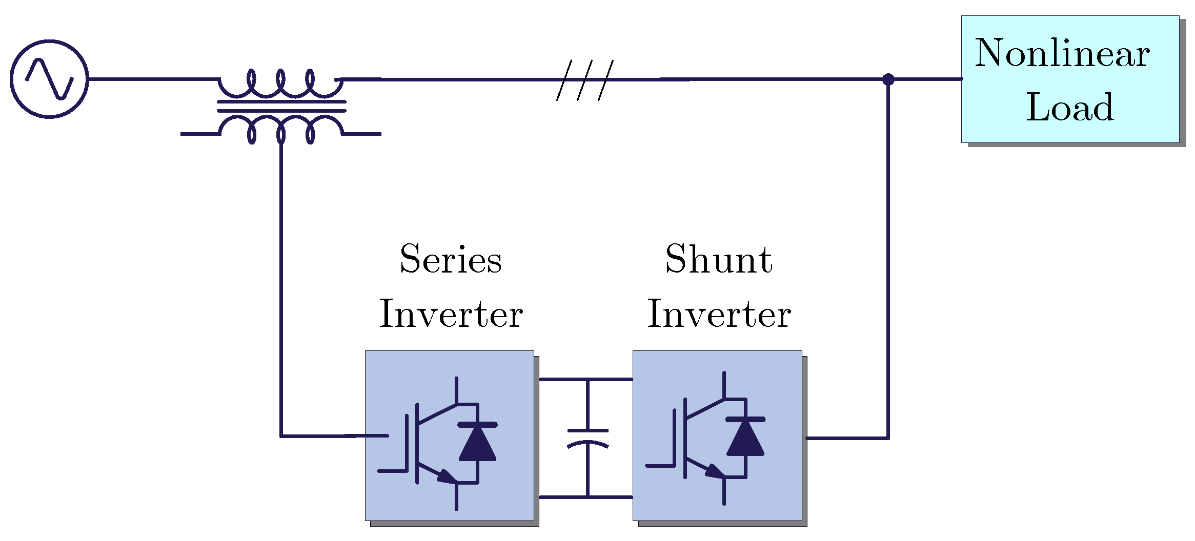
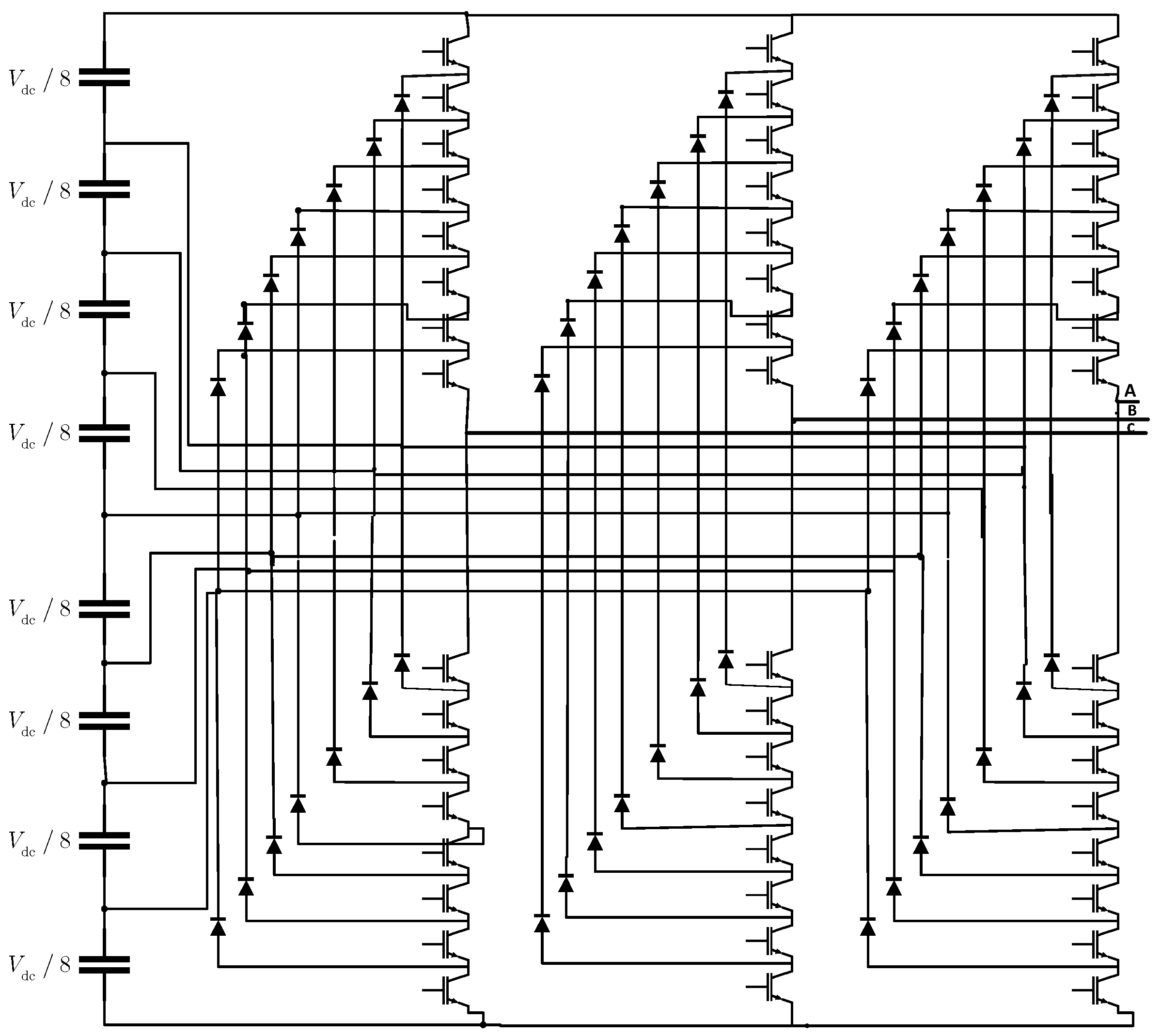
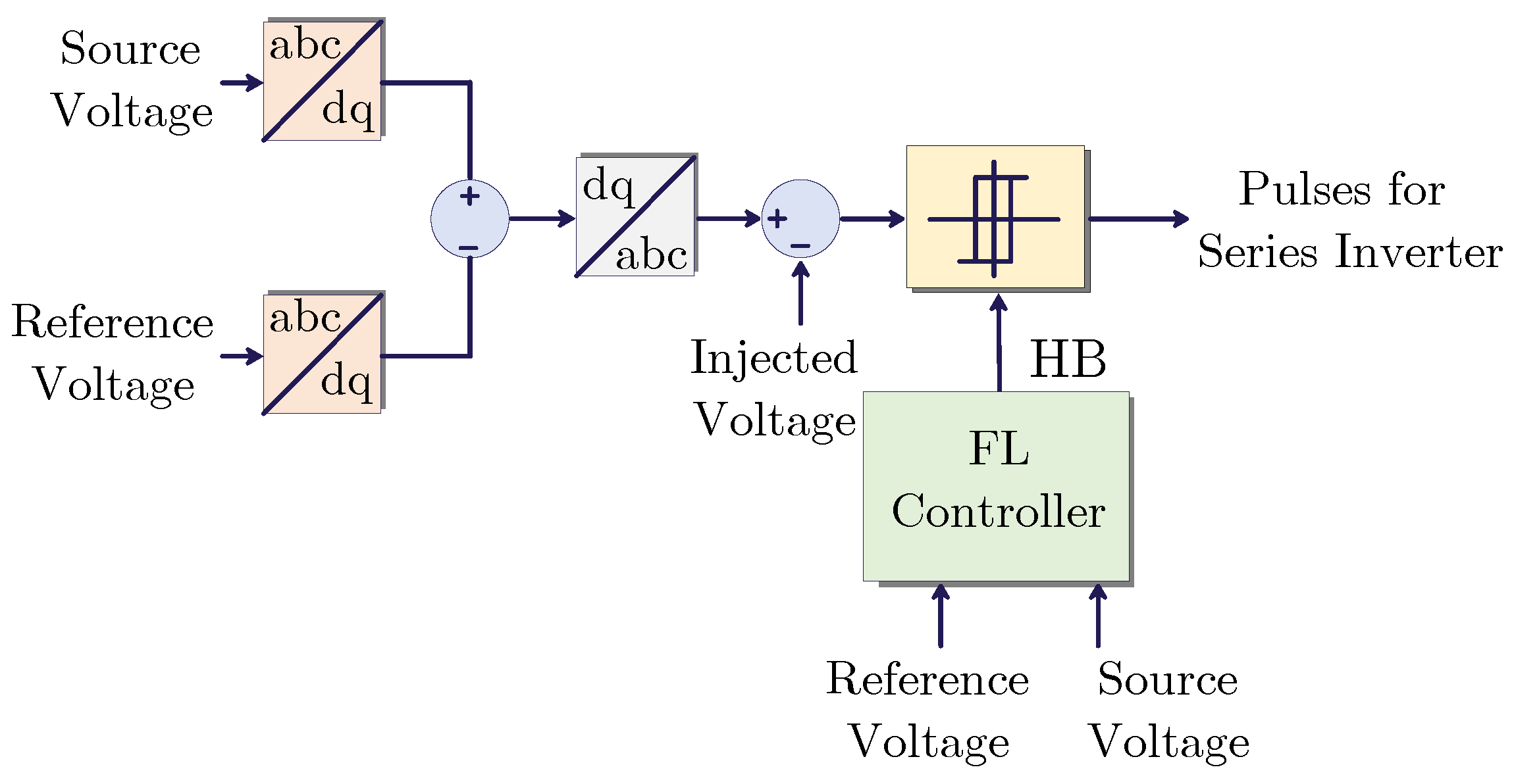
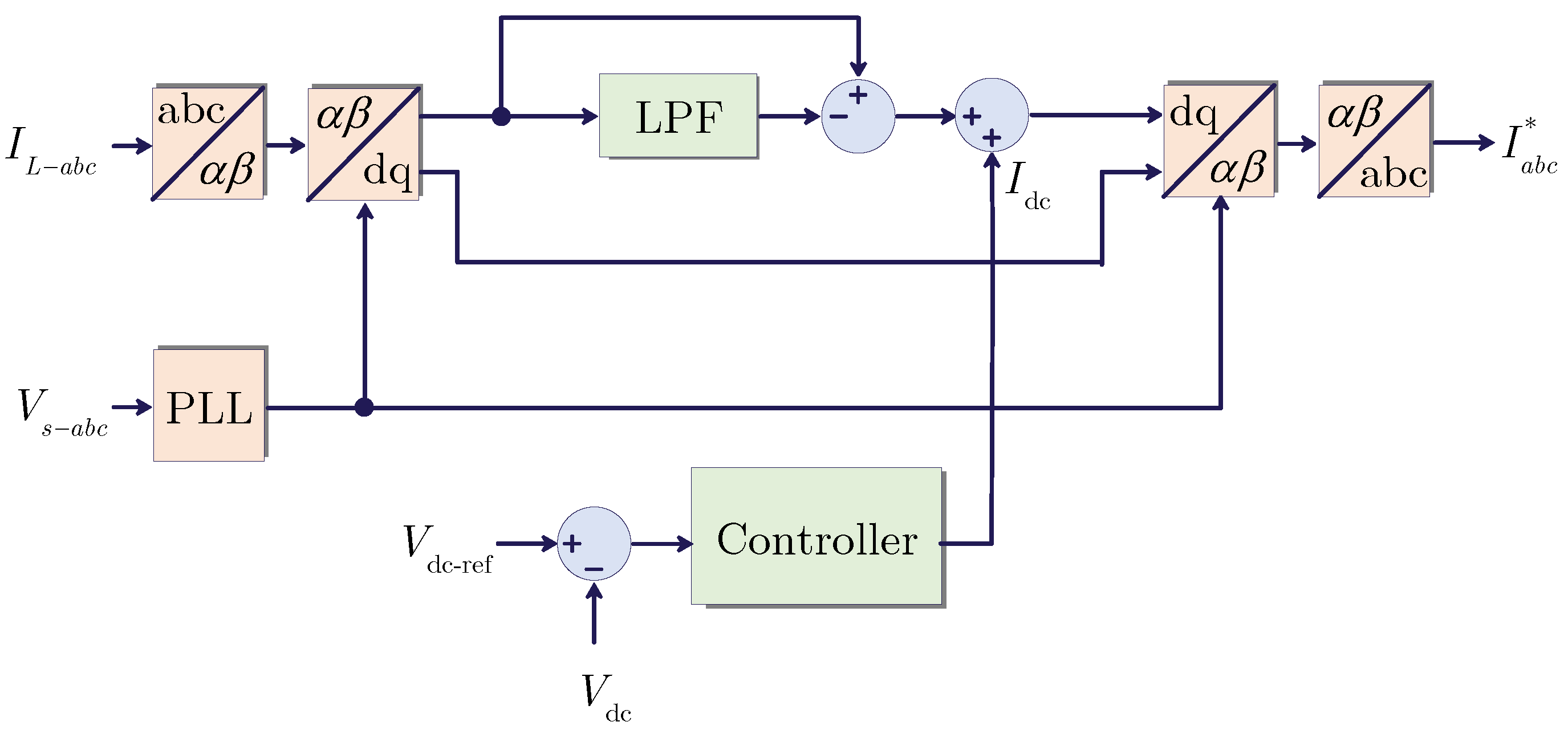
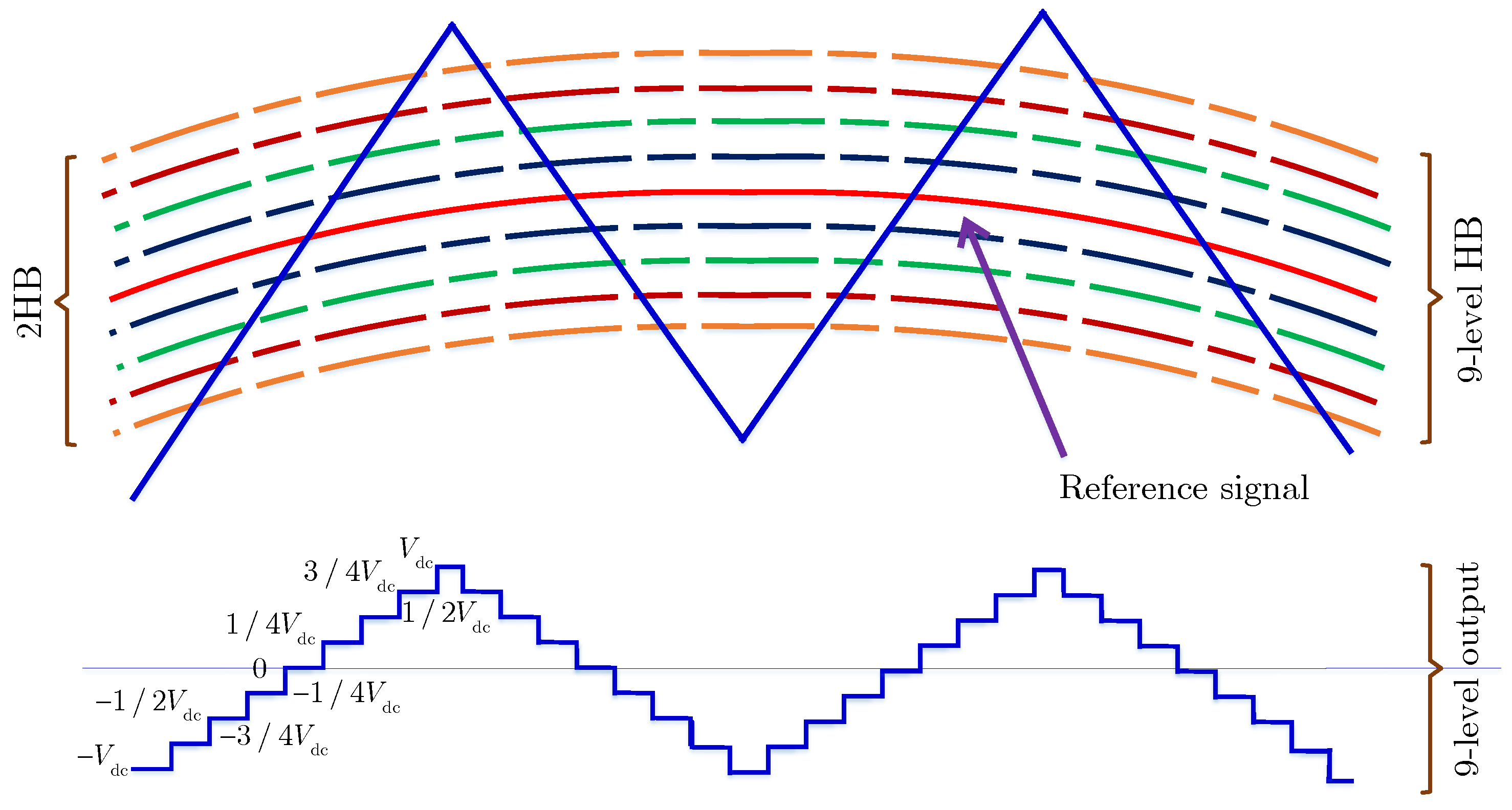
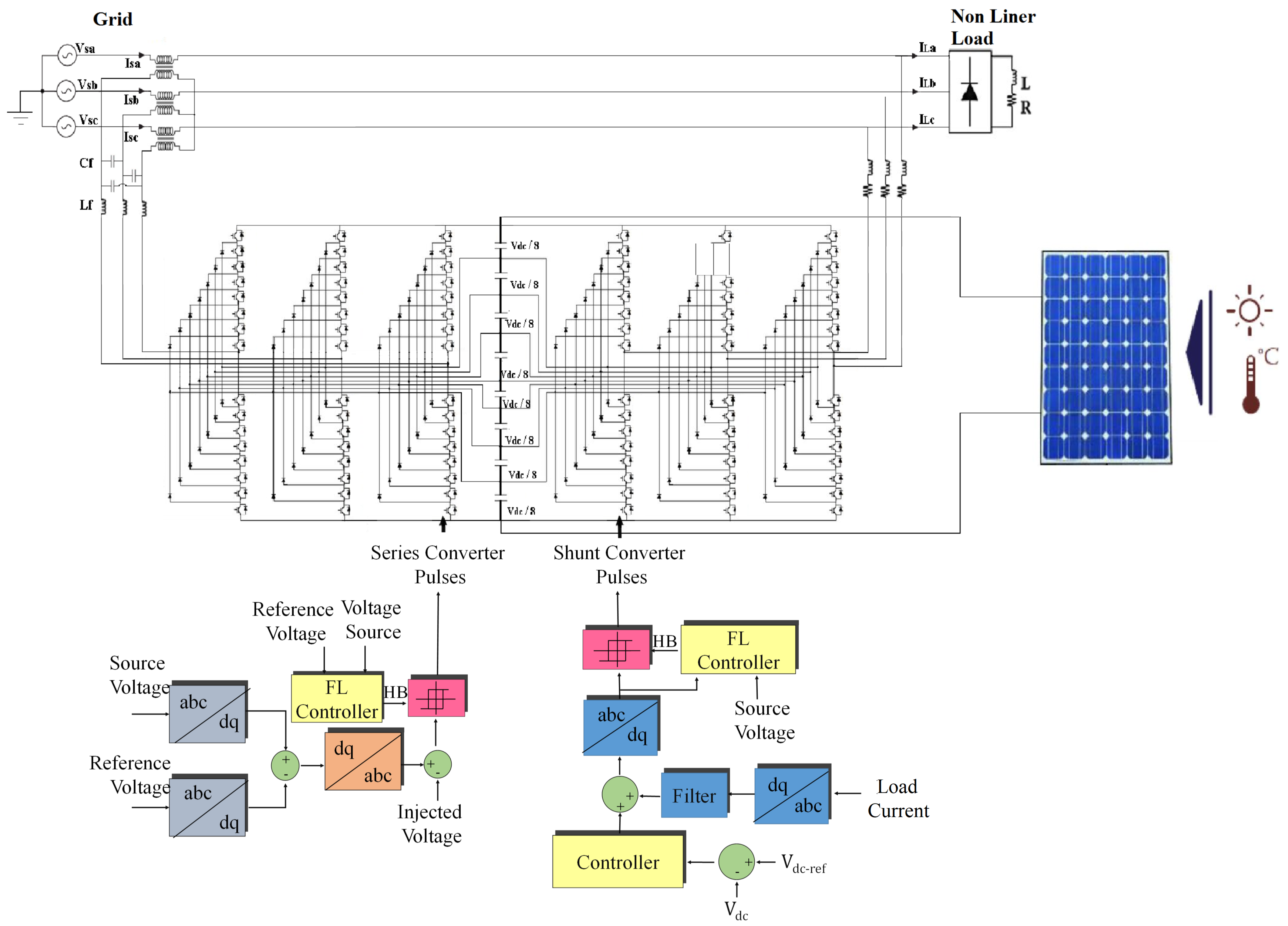
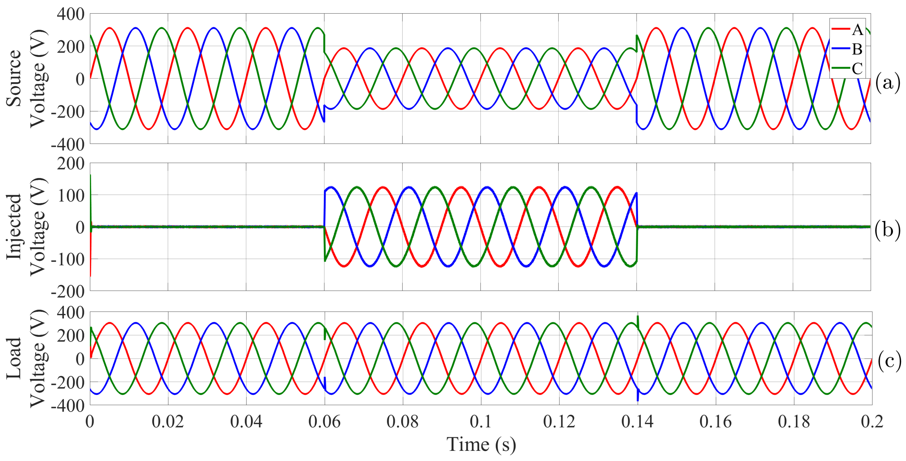
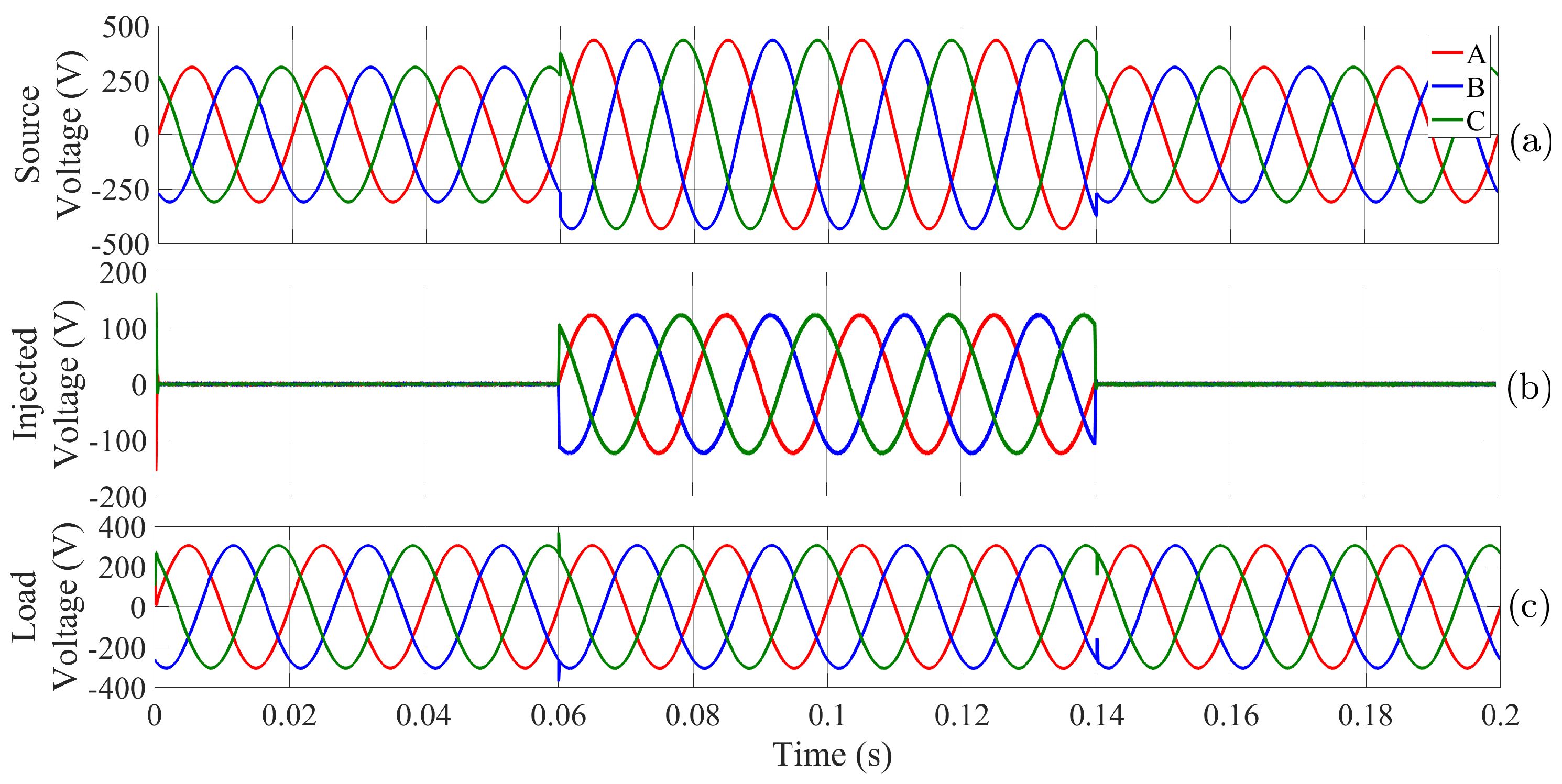
In this paper, a multi-level converter (9 levels) is suggested to operate as series and shunt converter of the UPQC. The synchronous reference frame (SRF) is proposed to extract the reference current and voltage signals, and the modulation technique in this paper depends on AHP with Fuzzy Logic (9 levels adaptive Hysteresis band), which is compared with other known modulation techniques such as SPWM; the advantage of the proposed method has been reached, without forgetting using solar array to feed the DC link, which matches both converters with required voltage. The obtained results are very important to prove that the effectiveness of the suggested UPQC system depends on nine-level inverter in reducing THD (less than 2%) for both voltage and current waveforms, in addition to enhancing the power quality.
The remainder of this paper is divided as follows: Section 2 illustrates the structure and control system of the UPQC. The proposed control modulation technique is illustrated in Section 3. Section 4 presents connecting the photovoltaic system and tracking of the maximum power points (MPPT). Section 5 presents the simulation results of the suggested system. Finally, conclusions are drawn in Section 6.

2. Structure of Multilevel Unified Power Quality Conditioner (UPQC)

Figure 1 presents the most common structure of the UPQC. It consists of two converters, one connected in series and the other in parallel with the load, and they share a common constant voltage link (DC link). Moreover, Figure 2 shows the nine-level multilevel converter structure used to implement the UPQC in this paper. Further details on the control implementation of these two converters are presented in the next three subsections.

2.1. Generating Reference Signals

There are several methods that can be used to generate reference signals (generation of reference voltages for the series converter, generation of reference currents of the parallel converter). Some of these methods depend on the frequency domain, such as the fast Fourier transform and the discontinuous Fourier transform. However, the main disadvantage of such methods is the very high computational cost (long time and large memory required) [14]. Other methods depend on the time domain such as the instantaneous active and reactive power theory and the SRF theory. The components of both voltage or current are continuous quantities in the SRF. However, the system cannot function properly in imbalance sceinarios as they lead to failure of control due to the second harmonics oscillations. Hence, additional control loops are required, which complicate the control system [15].

2.2. Control of the Series Converter

In case of voltage disturbances, the series converter will be operated. Figure 3 shows the control diagram for the series active filter. It can be seen that the SRF is used to generate the reference voltages that are obtained from the comparison of the measured voltage with a reference value with 1 p.u. amplitude and 120° phase displacement between the phases, as shown in Equation (1). Note that the initial voltage angle ( θ ) required for the abc-to-dq and dq-to-abc conversions is obtained via a phase locked loop (PLL) [16].
V a = sin ( ω t + φ ) V b = sin ( ω t + φ 2 π 3 ) V c = sin ( ω t + φ + 2 π 3 )
The abc-to-dq conversion is carried out using the park transformation depending on the Equation (2).
u d u q u 0 = 2 3 cos ( θ ) cos ( θ 2 π 3 ) cos ( θ + 2 π 3 ) sin ( θ ) sin ( θ 2 π 3 ) sin ( θ + 2 π 3 ) 1 2 1 2 1 2 u a u b u c
After that, the dq components are converted to abc coordinates using the inverse Park Transformation shown by Equation (3).
u a u b u c = cos ( θ ) sin ( θ ) 1 cos ( θ 2 π 3 ) sin ( θ 2 π 3 ) 1 cos ( θ + 2 π 3 ) sin ( θ + 2 π 3 ) 1 u d u q u 0

2.3. Control of the Parallel Converter

The shunt converter will be operated when current disturbances occur. Hence, the parallel active filter deals with power quality problems related to current and compensates for the reactive power. SRF is used to current signals extraction, and SRF can handle unbalanced voltages, where currents are handled independently of the supply voltage. The fundamental component of voltage or current in an SRF is the continuous quantities that can be easily extracted using suitable filters. Figure 4 presents the control structure of the converter. The reference signals are generated in the dq reference frame. Again, the transition from abc coordinates to the dq coordinates is done through Park transformation, where the transformation angle is obtained using the PLL. Figure 4 also shows the process of filtering out the high harmonics components by using appropriate low pass filter (LPF). Finally, via reverse Park conversion, the reference signals are obtained by transforming from the dq coordinates to the abc coordinates.

3. Proposed Modulation Technique

There are several techniques for generating pulses for electronic semiconductor switches such as linear techniques (e.g., PWM-SPWM-SVPWM), non-linear techniques (e.g., neural networks, fuzzy logic), and Hysteresis Band (HB). In this paper, the multilevel adaptive hysteresis band (ML-AHB) is presented to control the output voltage of the UPQC. This modulation technique is characterized by its fast response, accuracy in tracking capability, and less ripple. It is noteworthy that the bandwidth is variable and can be calculated mathematically or through artificial intelligence methods.
First, the source voltage ( V s ) signal and the reference signal ( V ref , I ref ) signals are fed to the fuzzy logic controller. Then, the Adaptive Hysteresis Band is obtained from the output of the fuzzy logic controller, as shown in Figure 5. Figure 6a,b show the procedure of generating the pulses for the parallel and series converters of phase (a), respectively. Figure 7 shows the nine-level adaptive Hysteresis Band that is being calculated by fuzzy logic controller. Table 1 presents the fuzzy logic rules used to determine the bandwidth (2HB). Five blurry (fuzzy) groups represented by triangular functions are used to characterize the output.

4. Connecting the Photovoltaic System and Maximum Power Point Tracking (MPPT)

The photovoltaic (PV) system is connected to the DC-Link, which is set between the series and parallel converters. This solar photovoltaic array is formed from the connection of 32 solar panels in series. Table 2 lists the paramters of the investigated KC200GT solar panel. The perturb and observation method is used in order to track the maximum power point (MPPT), where the corresponding voltage is 840 volts, at a radiation level of 1000 W/m2 and a temperature of 25 °C. Figure 8 presents the detailed control structure of the UPQC, including the photovoltaic array that injects its power to the constant DC-Link of 840 volts.

5. Simulation Results

To verify the performance of the proposed modulation technique, the UPQC system shown in Figure 8 is considered. In this system, the series and parallel filters are connected through DC link. Table 3 lists the parameters of the system. Seven cases of voltage and current disturbances are simulated, and the THD values of voltage and current waveforms are used for the comparison study with the conventional SPWM.

5.1. Voltage Sag

In this case study, the source voltage is source voltage waveform before and after it falls by 40% of its nominal value. Figure 9 shows the corresponding source voltage, injected voltage, and the load voltage. It can be seen that the UPQC reacts very quickly to the voltage sag and it injects a certain amount of the voltage in order to keep the load voltage equal to the desired nominal value.
Furthermore, Fourier transformation over the considered time duration (0.2 s) is used to calculate the THD for all phases before and after using UPQC, as shown in Table 4. It is evident that the voltage waveforms have much larger THD values before connecting the UPQC. The importance and effective role of the UPQC in general and the role of the AHB controller in particular for treating the voltage sag and eliminating its effects are emphasized. For example, the THD value of phase A when the AHB used is 0.63% of all phases. However, using the conventional SPWM has a THD equal to about 1.32%.

5.2. Voltage Swell

The grid voltage is increased to 140% of its nominal value in order to test the voltage swell scenarios. Figure 10 shows the voltage waveforms before and after applying the voltage increase by 40% of its nominal value. Table 5 shows a comparison of the THD values before and after activating the UPQC. It is clear that the UPQC ensures reliable supply to the load and that the THD value is much smaller when the AHB is used.

5.3. Compensation of Current Harmonics

Considering the load is non-linear, the harmonics are produced in the current waveforms. Figure 11 shows the current waveforms before and after the current harmonics compensation. It can be observed that the the harmonics are effectively compensated through the UPQC after is activated at 0.06 s. The corresponding THD values are reported in Table 6. The THD in the current waveforms is significantly reduced after enabling the UPQC.

5.4. Compensation of Current Harmonics for Asymmetric Load

When loading the first and second phases with an inductive-resistive load, the drawn current from the source is unequal between the three phases. Figure 12 shows the current waveforms of such a scenario. It can be seen that the current of asymmetric load is distributed unequally between the three phases. Figure 12 proves the ability of the UPQC to treat asymmetric disturbances as well. Here, as shown in Table 7, there is a significant decrease in THD of phase A from 18.2% before using the UPQC to 1.43% after using the UPQC.

5.5. Compensation of Voltage Harmonics

This case study investigates the performance of the UPQC when the source voltage waveforms contain background harmonics. Figure 13 shows the results of the source voltage, the injected voltage by the UPQC, and the load voltage. It can be seen that the load voltage is purely sinusoidal as the UPQC is enabled. As listed in Table 8, it can be seen that the THD value is decreased from 17.6% to 0.5% after enabling the UPQC. Additionally, Table 8 shows a comparison of the THD value when using in case of using SPWM and AHB to control UPQC for processing voltage harmonics. Thus, the low values of the THD shows the ability of the UPQC in general and UPQC controlled when the AHB is used. It reduces voltage harmonics that may occur in the grid. Therefore, the harmful effects of high harmonics and technical and economic problems on the consumers can be avoided.

5.6. Interruptions of Source Voltage

A sever case study is investigated in this case study. Figure 14 shows the source voltage interruption at 0.06 s. It can be seen from Figure 14b that the UPQC reacts rapidly to this event, and it regulates the load voltage to its nominal value. Furthermore, Table 9 shows large values of the THD before connecting the UPQC-PV. The effectiveness of the UPQC in general and the AHB controller in particular can obviouslt be used to eliminate the voltage interruption consequences.

5.7. Single Phase-to-Ground Fault

In order to test the UPQC performance in fault conditions, a single phase-to-ground fault in the source voltage is considered. In such scenarios, it is expected that the series converter will compensate the disturbances that occur in the concerned phase and provide the required voltage with-in the full time of the fault. Figure 15 confirms the effectiveness of the suggested filter to solve this problem. Figure 15 shows the occurrence of the phase-to-ground fault in the source voltage for four fundamental cycles. Before enabling the UPQC, the THD value of voltage of phase A is 53.86%, due to the mentioned fault. However, Figure 15b shows that the series converter compensates the disturbances within the fault period, where the THD value after compensation decreases to 1.9%. Furthermore, as listed in Table 10, it can be seen that the AHB outperforms the conventional SPWM technique.

6. Conclusions

This paper proposes a fuzzy logic modulation technique for a multilevel (ML) parallel-series conditioner (UPQC). The PV system is connected to the common DC link between the two converters that are working separately to compensate for voltage (series) and current (parallel) issues. The proposed UPQC-PV contributes to treating problems of imbalanced loading in three phases systems and to reducing the THD. Here, the increasing of level (to nine-level) compared to five- and seven- level contribute to further decreasing the rate of variation (dv/dt). The proposed control system was simulated (MATLAB/Simulink), and different perturbations were studied before and after enabling the compensation to verify the effectiveness of the proposed UPQC-PV. The simulation results verify that the voltage and current problems are effectively overcome by the proposed Adaptive Hysteresis Band using fuzzy logic control approach. Further research can explore possible applications of the suggested UPQC system for standalone microgrids where grid-forming inverters play a key role in such power-electronics-based electric systems.

Author Contributions

Conceptualization, H.K. and C.M.; methodology, H.K., C.M., I.H. and N.M.; software, H.K. and N.M.; validation, H.K. and C.M.; formal analysis, H.K. and N.M.; investigation, H.K., C.M. and N.M.; writing—Original draft preparation, H.K.; writing—Review and editing, C.M., I.H. and N.M.; visualization, H.K. and N.M.; supervision, C.M. and I.H.; project administration, C.M. and I.H. All authors have read and agreed to the published version of the manuscript.

Funding

This research received no external funding.

Conflicts of Interest

The authors declare no conflict of interest.

Abbreviations

The following abbreviations are used in this manuscript:
UPQCUnified power quality conditioner
AHBAdaptive hysteresis band
PVPhotovoltaic
PWMPulse-width modulation
SRFSynchronous reference frame
THDTotal harmonic distortion

References

  1. Sridhar, J.; Prakash, R. Power Quality Issues and Its Mitigation by Unified Power Quality Conditioner. In Proceedings of the International Conference on Current Trends in Engineering Science and Technology, ICCTEST, Bangalore, India, 5–7 January 2017. [Google Scholar]
  2. Mohammed, N.; Ciobotaru, M.; Town, G. Online parametric estimation of grid impedance under unbalanced grid conditions. Energies 2019, 12, 4752. [Google Scholar] [CrossRef] [Green Version]
  3. IEEE. IEEE Standard Definitions for the Measurement of Electric Power Quantities under Sinusoidal, Nonsinusoidal, Balanced, or Unbalanced Conditions; IEEE: Piscataway, NJ, USA, 2010. [Google Scholar]
  4. Akagi, H. Modern active filters and traditional passive filters. Bull. Pol. Acad. Sci. Tech. Sci. 2006, 54, 255–269. [Google Scholar]
  5. Zahira, R.; Fathima, A.P. A technical survey on control strategies of active filter for harmonic suppression. Procedia Eng. 2012, 30, 686–693. [Google Scholar] [CrossRef] [Green Version]
  6. Hussien, Z.; Atan, N.; Abidin, I. Shunt active power filter for harmonic compensation of nonlinear loads. In Proceedings of the National Power Engineering Conference, Bangi, Malaysia, 15–16 December 2003; pp. 117–120. [Google Scholar]
  7. Nabipour, M.; Razaz, M.; Seifossadat, S.G.; Mortazavi, S. A novel adaptive fuzzy membership function tuning algorithm for robust control of a PV-based Dynamic Voltage Restorer (DVR). Eng. Appl. Artif. Intell. 2016, 53, 155–175. [Google Scholar] [CrossRef]
  8. Paramanik, S.; Sarker, K.; Chatterjee, D.; Goswami, S. Smart grid power quality improvement using modified UPQC. In Proceedings of the 2019 Devices for Integrated Circuit (DevIC), Kalyani, India, 23–24 March 2019; pp. 356–360. [Google Scholar]
  9. Ali, M.; Khan, M.M.; Xu, J.; Faiz, M.T.; Ali, Y.; Hashmi, K.; Tang, H. Series Active Filter Design Based on Asymmetric Hybrid Modular Multilevel Converter for Traction System. Electronics 2018, 7, 134. [Google Scholar] [CrossRef] [Green Version]
  10. Varschavsky, A.; Dixon, J.; Rotella, M.; Morán, L. Cascaded nine-level inverter for hybrid-series active power filter, using industrial controller. IEEE Trans. Ind. Electron. 2009, 57, 2761–2767. [Google Scholar] [CrossRef]
  11. Geethalakshmi, B.; Kavitha, M.; Delhibabu, K. Harmonic compensation using multilevel inverter based shunt active power filter. In Proceedings of the 2010 Joint International Conference on Power Electronics, Drives and Energy Systems & 2010 Power India, New Delhi, India, 20–23 December 2010; pp. 1–6. [Google Scholar]
  12. Saad, S.; Zellouma, L. Fuzzy logic controller for three-level shunt active filter compensating harmonics and reactive power. Electr. Power Syst. Res. 2009, 79, 1337–1341. [Google Scholar] [CrossRef]
  13. Massoud, A.M.; Finney, S.J.; Cruden, A.J.; Williams, B.W. Three-phase, three-wire, five-level cascaded shunt active filter for power conditioning, using two different space vector modulation techniques. IEEE Trans. Power Deliv. 2007, 22, 2349–2361. [Google Scholar] [CrossRef]
  14. Vinnakoti, S.; Kota, V.R. Implementation of artificial neural network based controller for a five-level converter based UPQC. Alex. Eng. J. 2018, 57, 1475–1488. [Google Scholar] [CrossRef]
  15. Campanhol, L.B.; da Silva, S.A.; Azauri, A. A three-phase four-wire grid-connected photovoltaic system using a dual unified power quality conditioner. In Proceedings of the 2015 IEEE 13th Brazilian Power Electronics Conference and 1st Southern Power Electronics Conference (COBEP/SPEC), Fortaleza, Brazil, 29 November–2 December 2015; pp. 1–6. [Google Scholar]
  16. Subrahmanyam, K.; Gopal, B. PV system integration with multilevel-UPQC for power quality improvement in distribution system. Mater. Today Proc. 2020; in press. [Google Scholar] [CrossRef]
  17. Muneer, V.; Bhattacharya, A. Cascaded H bridge multi level inverter based unified power quality conditioner. In Proceedings of the 2018 IEEE 8th Power India International Conference (PIICON), Guangzhou, China, 14–16 May 2018; pp. 1–6. [Google Scholar]
  18. Vinothkumar, V.; Kanimozhi, R. Power flow control and power quality analysis in power distribution system using UPQC based cascaded multilevel inverter with predictive phase dispersion modulation method. J. Ambient. Intell. Humaniz. Comput. 2021, 12, 6445–6463. [Google Scholar] [CrossRef]
  19. Gupta, A. Power quality evaluation of photovoltaic grid interfaced cascaded H-bridge nine-level multilevel inverter systems using D-STATCOM and UPQC. Energy 2022, 238, 121707. [Google Scholar] [CrossRef]
  20. Sekhar, A.H.; Bharathi, S.L.K.; Asif, N.A.H.; Manikandan, P.V. Power Quality Enhancement Using Multi-Level Inverter with UPQC and Robust Back Propagation Neural Network Strategy. SPAST Abstr. 2021, 1. Available online: https://spast.org/techrep/article/view/2967 (accessed on 1 February 2022).
  21. Shriwastava, R.; Daigavane, M.; Wagh, N. Comparative Analysis of Three Phase 2-Level VSI with 3-Level and 5-Level DCMLI Using CB-SVM. In Proceedings of the IEEE International Conference on Electrical, Electronics, Computers, Communication, Mechanical and Computing (EECCMC-2018), Tamil Nadu, India, 28–29 January 2018; pp. 4304–5386. [Google Scholar]
  22. Haris, M.; Pathak, M.; Agarwal, P. Comparison of SPWM multilevel inverter fed PMSM drive with two level inverter fed drive. In Proceedings of the International Conference on Recent Advances and Innovations in Engineering (ICRAIE-2014), Jaipur, India, 9–11 May 2014; pp. 1–5. [Google Scholar]
  23. Benanti, S.; Buccella, C.; Caruso, M.; Castiglia, V.; Cecati, C.; Di Tommaso, A.; Miceli, R.; Romano, P.; Schettino, G.; Viola, F. Experimental analysis with FPGA controller-based of MC PWM techniques for three-phase five level cascaded H-bridge for PV applications. In Proceedings of the 2016 IEEE International Conference on Renewable Energy Research and Applications (ICRERA), Birmingham, UK, 20–23 November 2016; pp. 1173–1178. [Google Scholar]
  24. Lezana, P.; Pou, J.; Meynard, T.A.; Rodriguez, J.; Ceballos, S.; Richardeau, F. Survey on fault operation on multilevel inverters. IEEE Trans. Ind. Electron. 2009, 57, 2207–2218. [Google Scholar] [CrossRef] [Green Version]
  25. Hafezi, H.; Faranda, R. A new approach for power losses evaluation of IGBT/diode module. Electronics 2021, 10, 280. [Google Scholar] [CrossRef]
  26. Kouro, S.; Malinowski, M.; Gopakumar, K.; Pou, J.; Franquelo, L.G.; Wu, B.; Rodriguez, J.; Pérez, M.A.; Leon, J.I. Recent advances and industrial applications of multilevel converters. IEEE Trans. Ind. Electron. 2010, 57, 2553–2580. [Google Scholar] [CrossRef]
  27. Szromba, A. The unified power quality conditioner control method based on the equivalent conductance signals of the compensated Load. Energies 2020, 13, 6298. [Google Scholar] [CrossRef]
  28. Patjoshi, R.K.; Mahapatra, K. Resistive optimization with enhanced PLL based nonlinear variable gain fuzzy hysteresis control strategy for unified power quality conditioner. Int. J. Electr. Power Energy Syst. 2016, 83, 352–363. [Google Scholar] [CrossRef]
  29. Rai, S.K.; Mathew, L.; Shimi, S. Software and Hardware Implementation of a Nine Level Inverter with Low Component Count. In Proceedings of the IECON 2020 The 46th Annual Conference of the IEEE Industrial Electronics Society, Singapore, 18–21 October 2020; pp. 3318–3324. [Google Scholar]
  30. Arulmurugan, R.; Chandramouli, A. Design and implementation of a nine-level inverter with shunt active filter for distributed system. In Proceedings of the 2018 4th International Conference on Electrical Energy Systems (ICEES), Chennai, India, 7–9 February 2018; pp. 224–228. [Google Scholar]
  31. Yusof, N.A.; Sapari, N.M.; Mokhlis, H.; Selvaraj, J. A comparative study of 5-level and 7-level multilevel inverter connected to the grid. In Proceedings of the 2012 IEEE International Conference on Power and Energy (PECon), Kota Kinabalu, Malaysia, 2–5 December 2012; pp. 542–547. [Google Scholar]
Figure 1. Structure of the Unified Power Quality Conditioner (UPQC).
Electronics 11 00919 g001
Figure 2. Structure of the converter used in the multilevel UPQC.
Electronics 11 00919 g002
Figure 3. Control diagram of the series active filter.
Electronics 11 00919 g003
Figure 4. Control diagram of the shunt converter.
Electronics 11 00919 g004
Figure 5. Calculating the Adaptive Hysteresis Band (HB) using fuzzy logic: (a) for current and (b) for voltage.
Electronics 11 00919 g005
Figure 6. The generation of pulses for both parallel (a) and series (b) converters of phase a through AHB.
Electronics 11 00919 g006
Figure 7. The nine-level adaptive hysteresis band.
Electronics 11 00919 g007
Figure 8. Simulation of the suggested system.
Electronics 11 00919 g008
Figure 9. The simulation results of the 40% symmetrical voltage sag with a duration of 80 ms: (a) Source voltage, (b) injected voltage, and (c) load input voltage.
Electronics 11 00919 g009
Figure 10. The simulation results of the voltage swell (a) Source voltage, (b) injected voltage, (c) load voltage.
Electronics 11 00919 g010
Figure 11. The simulation results of the current waveform before and after compensation the harmonics: (a) load current, (b) filter current, and (c) source current.
Electronics 11 00919 g011
Figure 12. The simulation results of the current waveforms before and after compensation harmonics for the asymmetric load (a) load current, (b) UPQC current, and (c) source current.
Electronics 11 00919 g012
Figure 13. The simulation results of voltage harmonics (a) Source voltage, (b) injected voltage, and (c) load voltage.
Electronics 11 00919 g013
Figure 14. The simulation results of the voltage interruption (a) Source voltage, (b) injected voltage, and (c) load voltage.
Electronics 11 00919 g014
Figure 15. The simulation results of the phase interruption (a) Source voltage, (b) injected voltage, and (c) load voltage.
Electronics 11 00919 g015
Table 1. Fuzzy groups used to determine the bandwidth.
VsNLNMZEPMPL
dic/dt,
dv/dt
NLPVSPSPSPMPM
NMPSPSPSPMPM
ZEPLPLPVLPLPL
PMPMPMPSPSPS
PLPMPMPSPSPVS
Table 2. The parameters of the KC200GT solar panel.
DescriptionValueUnit
Maximum power200W
Maximum power voltage26.3V
Maximum power current7.61A
Open circuit voltage32.9V
short circuit current8.21A
Numbers of serial cells54-
Table 3. The parameters of the system.
QuantityValueUnit
Line to line voltage of the grid380V
Phase voltage of the grid220V
Maximum phase voltage311V
Grid frequency50Hz
Load impedanceR = 15 Ω
L = 30mH
Transformation ratio1:1-
Reference DC Voltage840V
Line impedance R L = 0. 1 Ω
L L = 10µH
Switching frequency5kHz
Shunt filter impedanceR = 1
L = 2.1mH
Table 4. The voltage THD for the case of voltage sag.
PhaseSource THD%THD% Using SPWMTHD% Using AHB
A15.151.320.63
B15.51.360.69
C15.321.370.7
Table 5. The voltage THD for the case of voltage swell.
PhaseSource THD%THD% Using SPWMTHD% Using AHB
A10.971.050.29
B11.021.060.31
C10.981.080.32
Table 6. The current THD for the case of current harmonics.
PhaseSource THD%THD% Using SPWMTHD% Using AHB
A23.972.721.49
B24.12.761.5
C24.042.771.5
Table 7. The current THD for the case of asymmetric loading.
PhaseSource THD%THD% Using SPWMTHD% Using AHB
A18.22.291.43
B18.162.241.43
C20.222.261.44
Table 8. The THD for the case of voltage harmonic compensation.
PhaseSource THD%THD% Using SPWMTHD% Using AHB
A17.671.110.55
B17.691.140.58
C17.71.120.56
Table 9. The THD for the case of voltage interruption.
PhaseSource THD%THD% Using SPWMTHD% Using AHB
A53.862.321.65
B53.92.361.68
C53.892.371.69
Table 10. The THD for the case of voltage interruption in the first phase.
PhaseSource THD%THD% Using SPWMTHD% Using AHB
A53.862.521.90
B0.282.461.89
C0.292.451.88
Publisher’s Note: MDPI stays neutral with regard to jurisdictional claims in published maps and institutional affiliations.

