1. Introduction
The depletion of natural resources and the continuously growing population of the planet are posing a difficult to tackle situation for the agricultural sector [
1]. Assisted by the wide bouquet of modern innovative technologies, the digital transformation of this sector seems to be a promising direction for making problems less intense [
2]. This transformation requires well-skilled personnel, and thus, all groups of people getting involved in the agricultural processes, from students and teachers/academics to farmers and their consultants, should be able to understand and use the diverse technological innovations dominating this area. The latter is not an easy objective, but educational systems worldwide have already started to become more responsive to such demanding circumstances, as it is now apparent that learners all over the world should acquire diverse skills preparing them for jobs that have not been invented yet [
3].
Towards this direction, the educational curricula are updated incorporating various STEM (Science, Technology, Engineering and Mathematics) activities that often encourage the learners to participate in the design, implementation and testing stages of actual systems. Many innovative solutions are widely available to successfully support laboratory-level trials, thus aiming at creating interesting projects involving microcontrollers and pairing electronics that are quite inexpensive [
4]. Indeed, a considerable work is done using small and affordable systems, such as robotic devices, typically through Project Based Learning (PBL) approaches [
5], for primary and secondary education [
6,
7] and for the universities [
8,
9], where more effort should be made [
10]. The incorporation of STEM/robotic paradigm into the modern educational practices is not always a flawless process [
11,
12]. Furthermore, as the students are becoming more experienced, they ask for more demanding learning scenarios of convincing role and size that better match real-world situations. The gap between academia and industry, in terms of suitable engineering skills potential, is apparent [
13,
14] and easier to be bridged, in terms of pure software development, using open software environments [
15]. However, the software platforms are also extremely valuable for facilitating robotic system development and/or programming controllers of industrial specifications [
16,
17,
18], with the agriculture not being an exception [
19]. For these reasons, in many cases, the creation of satisfactory educational scenarios requires additional equipment (e.g., electromechanical components) that is quite pricy, if newly purchased. In such cases, the utilization of retired or scrapped components is a promising alternative. Apart from that, the selection of similar components is in pace with the general directions for sustainability and recycling that modern societies should follow [
20].
In terms of agricultural education, many approaches at the universities are limited to web-enhanced solutions, using ICT technologies as a facilitator for general content delivery [
21]. When trying to add the “engineering” term, the higher education practices are based almost on the same miniature electromechanical and power electronic components (e.g., LEDs, tiny DC motors, and cheap low-voltage motor controllers) that are utilized by the typical secondary education laboratory activities [
22,
23], and thus do not offer realistic enough learning experiences, despite their overall significance. Some other university contributions are focusing rather on the sensing and/or on the visualization software part of indicative agricultural processes [
21] than on the acting part, for reasons related to the difficulties of fluently adopting the Precision Agriculture (PA) context [
24], or they rely upon industrial modules or robotic platform solutions, such as the ones presented in [
25,
26,
27], that are valuable but quite complex and expensive. In the vast majority of cases, the main priority at the universities is to advertise the performance efficiency of their specific implementations, from the technical perspective, and not to highlight the underlying educational methods and the corresponding outcomes and societal impact [
28]. It must be noted that the students of the sector are demonstrating strong preference for experiential learning-based teaching methods which provide skills for making judgements, innovation and creation [
21,
29]. Digital agriculture is a field which involves agriculture, mathematics, engineering, computing science, and more, and thus, it is very difficult to find experts that are knowledgeable in all of the aspects of digital agriculture [
28]. The inefficiencies being experienced are partially related to the fact that, in the case of PA, the educators need to have increased analysis and synthesis abilities and thus be able to organize and promote innovative activities in an interdisciplinary and cooperative manner, which historically has not been a strength of academicians [
30].
The proposed work, willing to bridge the abovementioned gaps, firstly highlights the feasibility of delivering a cost-effective system of realistic size that generates automatically adjustable airflow, using a retired electric fan borrowed from an old agricultural facility and fixed on a metal frame. The core single phase AC (alternating current) electric motor was upgraded in order for the airflow to be controlled remotely by a tablet/smart phone device, using simple electronic equipment. The availability of easy-to-access and use programming software of either textual or visual nature simplified drastically the whole approach. Indeed, the role of the open source software and of the open source hardware is of dominant importance for the digital transformation and the profitable development of the societies, according to the recent final study report of the European Commission (EU) [
31]. Secondly, from the educational point of view, the proposed upgrade process, which is mainly destined for (but not constrained to) students of agricultural engineering, is exploited for better communicating the fundamentals of automatic control, several hardware, software and networking principles. The challenging teamwork required for the completion of the proposed system provides also the necessary environment for reinforcing several cooperative and organizational skills.
Consequently, the main contribution of this work is exactly to highlight the way that the participating software and hardware components can be combined together and exploited in order to deliver, at very low-cost levels, an effective instrument for maximizing the educational benefits from this upgrade process of a retired electromechanical system. The skills acquisition process is drastically facilitated by the realistic dimensions of the whole construction, while apart from hard skills, also valuable soft skills are reported by the participating students and future professionals.
In the following, efforts were made in order to keep a good balance between technical and educational content, and thus satisfying both categories of interested people potentially reading this article. Apart from this introduction,
Section 2 provides design and methodology details,
Section 3 highlights several implementation steps and challenges,
Section 4 is dedicated to the evaluation of the outcomes of the proposed system, from both technical and educational aspect, while
Section 5 contains concluding remarks and plans for future exploitation.
2. Methodology and Design Overview
This section is trying to further specify and explain the motives, the methodology and the design characterizing the activity of upgrading the retired ventilation equipment. In this regard,
Section 2.1 aims to explain the relation between some critical technological operations and the qualitative and quantitative improvement perspectives of modern agriculture and to throw light on the main barriers envisaged by the modern technical university curricula.
Section 2.2 is further focusing on the agricultural education specifying the educational objectives and settings for both hard and soft skills acquisition. Finally,
Section 2.3 provides a brief overview of the upgraded farm ventilation system, in order to better communicate the reasons behind its architecture and facilitate the comprehension of the rest of this article.
2.1. Motives and Challenges
Internet of things (IoT), as a basic pillar of the PA, is an emerging technology that includes devices connected to the Internet equipped with sensors, transducers, radio transceivers, and actuators comprising a functioning of the whole that gathers interchanges and responds to information [
32]. In this regard, the IoT plays a crucial role in making agricultural automation more efficient, and thus fostering production [
33]. Several recent works highlight the contribution of the IoT technologies in critical operations typically falling into the categories of protected agriculture [
34], optimized greenhouse control [
35], precision livestock farming [
36], and of optimized fresh products storage [
37]. The ability of monitoring and altering/controlling critical parameters, from temperature and humidity to important gas emissions produced by animals or plants, is a key process that every agricultural engineering professional has to be acquainted with, while the proper ventilation of the farm premises plays a dominant role in controlling the latter parameters. By studying the relevant literature, it can be concluded that, despite the positive role of the IoT technologies in the digital transformation of agricultural sector, more attention is put on the sensing part rather on actuator component management part, for a plethora of reasons varying from incompatibility issues to data ownership constraints [
38,
39], while the cost of a retail IoT solution can be from very low to considerably high, depending on the parameters, the accuracy and the functions being offered [
40].
Conventional electrical and electronics engineering courses pose several difficulties to students as they involve a difficult-to-master theoretical background, strong conceptuality and flexible circuit changes. As the discussed trend towards the IoT continues, it is of utmost importance to reform traditional curricula that introduce new students to the fundamentals of this area. To this end, the related ideas should be presented in a precise manner, so that students can rapidly absorb the key concepts and be able to apply them to emerging technologies [
41].
On the other hand, the so-called advanced manufacturing, which describes the use of creative technologies and techniques to enhance business competitiveness, is regarded as an important component of modern engineering education curricula [
16,
42]. As such, STEM departments strive to cope with new manufacturing technologies that become available and develop their laboratories in order to provide their students with adequate instruction and experiences directly linked to real-world situations. These requirements can be satisfactorily met by departments having sufficient financial support to create new laboratories. However, the majority of STEM departments operate nowadays under constantly decreasing budgets.
For these reasons, it is a considerable priority to enrich the education process in technical universities with exemplification and practices that facilitate the acquisition of skills aligned with the IoT technologies, while any solution reducing the relevant costs is more than welcome. Perhaps resource-limited university departments may not be able to provide training education on the state-of-the-art of manufacturing technology, but they can still improve the quality of instruction by providing their students with valuable training on manufacturing technology integration without major capital expense. To this end, departments should heavily rely on the already existing manufacturing/industrial equipment, even if being retired, as well as on open source hardware and software platforms, and definitely on a considerable amount of inventiveness.
From practical aspect of view, the option of utilizing/visiting real (e.g., agricultural) working premises for educational purposes is appealing but requires vicinity of these premises with the university campus and, as these premises are exploited by agri-food professionals, the didactic benefits from elongated experimentation or experimentation with extreme settings should be excluded, as such activities are not allowed because they might result in both production losses and degradation of expensive equipment.
2.2. Educational Settings and Objectives
From a pedagogical perspective, it is envisaged that the construction of an actual model system, such as a system for a precision agriculture application, apart from facilitating the study of the actual automatic control techniques and dynamics [
43], will serve as an important tool for problem-solving, integrate different discipline domains, help study the dynamic interaction among different scientific disciplines and social domains and lead to a fruitful direction to develop STEM pedagogy through authentic practices. Note that a characteristic view of the STEM pedagogical guidelines and of the relevant trends is available in [
44,
45,
46,
47] and references therein, while the benefits from combining STEM methods with agricultural practices are mutual and important [
48,
49].
In this regard, targeting at a more efficient agricultural engineering education, a retired ventilation motor system was exploited and transformed to a multilevel educational instrument. The basic objectives of the proposed approach, in terms of hard skills acquisition, were:
Better understanding of the automatic control principles;
Better understanding of the network communication principles;
Improving the skills of hardware assembling;
Improving the skills of programming microcontrollers and smart devices;
Better understanding of the sensor and actuators principles.
Furthermore, in order to better foster the educational outcomes of the students training, the acquisition of several soft skills was among the most important priorities of this approach, such as:
Reinforcing of the participants’ confidence that they can complete a project according to the given specifications;
Improving the communication and team working potential of the participants;
Improving the self-esteem of the students and their confidence to the professors;
Improving the ability of the participants to tackle occasional implementation difficulties which are rather be seen as meaningful learning opportunities;
Participants are becoming better in compiling innovations;
Participants are becoming better in documenting and presenting their achievements.
During the eight-month period of the core robotic activities, the groups of people being involved in where: professors of agricultural engineering (typically, one or two persons per activity/lesson), students during their final thesis, students during their internship period, and of course, students during their curricular lessons’ activities. The latter category of students attended a combination of the courses: “Applications of Informatics in Agriculture”, “Measurements and Sensors”, “Electronics and Microprocessors”, “Precision Agriculture”, “Automatic Control Processes”, and “Applied Automatic Control”. The majority of students were 20 to 25 years old.
Due to the diversity of the people getting involved and to the occasional constraints caused by the COVID-19 pandemic, the degree of each individual contribution to the discussed system upgrade process varied drastically. Despite that, a team formation schema was necessary, trying to recruit each group with participants of diverse but complementary potential, following to a certain degree the methods presented in [
50]. The project was exploiting the principles of the Project-Based Learning model (PBL) [
5] and of the of Collaborative Learning (CL) model [
51], following the successful outcomes of previous studies [
9]. The professors (typically one or two persons per activity/lesson) supervised the overall process. The students within the teams expressed their ideas and worked together to search for information, understand techniques, experiment, and implement the communication and control tasks. The more experienced students were functioning as mentors for the others [
52], thus assisting their professors.
As explained in
Section 1, universities use either the same miniature equipment as the secondary education institutions, which is insufficient to cover the increased needs of their students [
14] that ask for experiences matching the real processes applied by professionals, or have to compromise with expensive constructions that operate as “black box” systems, thus limiting the opportunities for creativity and experimentation with diverse settings. On the other hand, the old equipment of convincing dimensions, if present, is not computerized nor compliant in general with the common modern interfaces for communication, monitoring and control [
53]. Consequently, the process of upgrading is not straightforward and needs further highlighting. It must be noted that the engagement of robotic vehicles and/or robotic arms [
54] in the educational process is more common and possibly more attractive than the selection of a retired ventilation fan but is also more expensive and complex to be implemented, and thus, it somehow distracts the non-expert students from understanding the basic principles of the automatic control theory. As amongst the main obstacles for the application of robotics in higher education is the lack of standardized programming methods and the lack of sufficient multidisciplinary background skills by both instructors and students [
55], the selection of comparatively simple electronic components and well-known programming tools is a necessity. For this reason, the activity being presented updates a system of convincing dimensions but remains simple and utilizes components and tools having the latter characteristics, which are very important.
2.3. Basic System Overview
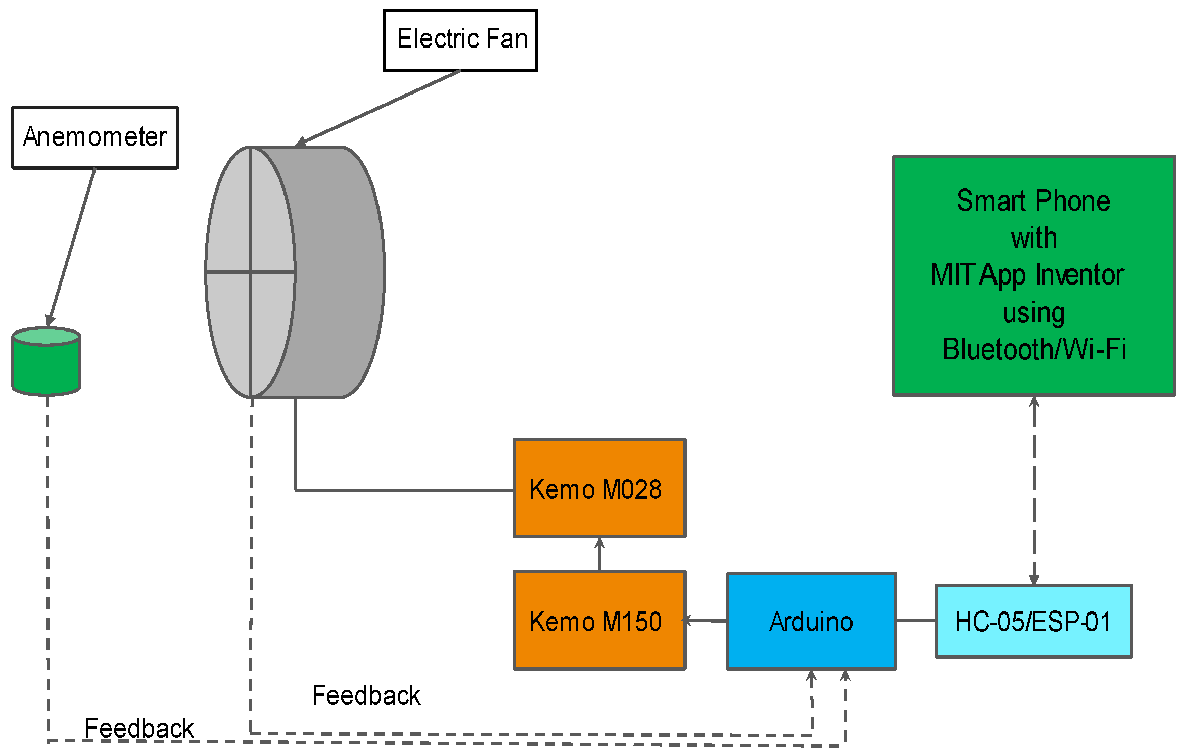
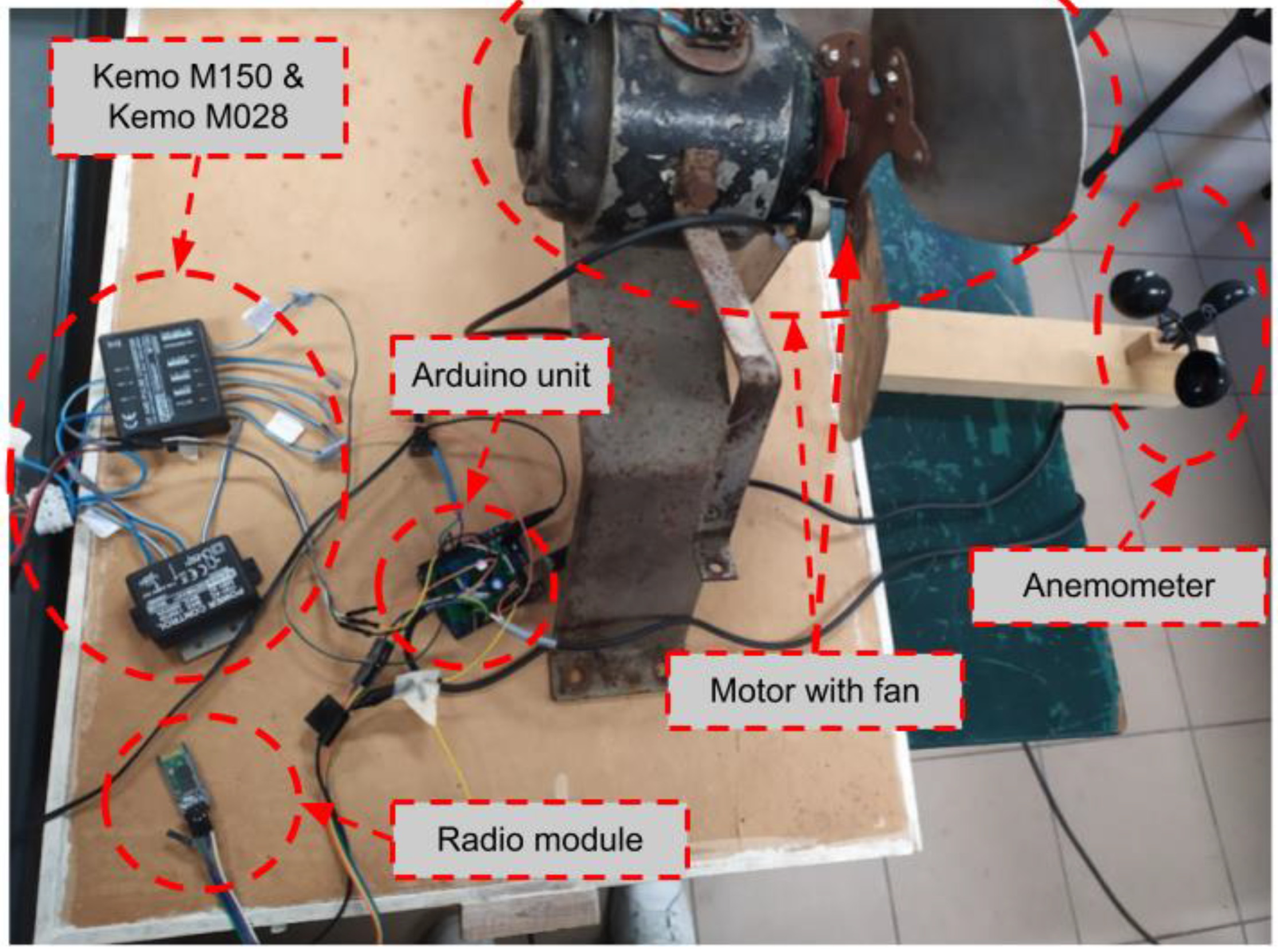
Technically speaking, an Arduino uno [
56] unit, a Kemo M150 [
57] and a Kemo M028 [
58] were interconnected in order to achieve efficient phase control of a single-phase AC fan motor via the suitable output signals. A custom anemometer was used for measuring the airflow generated by the fan as a feedback signal. For better capturing the behavior of the motor, a photo interrupter and a magnetic Hall sensor were used for estimating the rotational speed of the fan. The airflow measured by the anemometer (or, equivalently, the rotational speed estimated by the Hall sensor or the photo interrupter) was used as the main feedback mechanism for the Arduino-implemented PID-type controller [
59]. The latter mechanism calculated the PWM quantities of the arduino’s output which was driving the Kemo modules, thus adjusting the speed of the fan. In order to achieve short-range remote control of this ventilation system, a HC-06 Bluetooth module [
60] had initially been used. At a next stage, as “key” element of this remote control mechanism, an ESP-01 radio was utilized, which is indeed an ESP8266-based Wi-Fi module [
61]. This transceiver was achieving greater controlling distances and connectivity options compared with the Bluetooth solution. The whole programming of the Arduino unit was done via the Arduino IDE [
62] environment while and the MIT App Inventor [
63] visual block programming software was utilized for implementing the code running on the user’s mobile device. Both environments have flourishing support communities and numerous relevant application examples and tutorials are available in the cloud. Simple programming activities for the comparatively inexperienced arduino users can be orchestrated using the Ardublock [
64] visual blocks add-on for the Arduino IDE environment. The functionality provided by the basic air flow control mechanism design is depicted in
Figure 1.
Apart from the values directly adjusted or inspected using the smart phone/tablet device, the (hardware) USB connection between the Arduino and a laptop was facilitating the direct programming of the Arduino unit and providing details of the overall system dynamics via the Serial Monitor and the Serial Plotter tools of the Arduino IDE environment. This basic configuration was the basis for further upgrades utilizing well-known hardware and software components, such as the Raspberry Pi [
65] microcomputer board, the linux operating system environment, python and web programming principles and modules, and for improved interaction with both local and remote systems.
The whole design and implementation were intentionally kept very modular, in order to provide a clear view of the discrete role of each component (e.g., automatic control algorithm behavior, network connectivity, sensing and acting elements manipulation, etc.). This decision was in-line with the university lessons’ curriculum and was assisting the demystification of modern technologies by the agricultural engineering students. In addition to this, even if working with comparatively simple components, the implementation challenges triggering students’ interests were not few, especially due to the scaled-up character of the proposed system.
3. Implementation Details and Challenges
This section is dedicated in explaining the most important implementation details and challenges of the proposed electromechanical system upgrade. More specifically,
Section 3.1 provides technical details for hardware and software issues mainly referring to the large AC ventilation motor being upgraded. Similarly,
Section 3.2 provides hardware and software details for the equipment at the operator’s end.
Section 3.3 focuses in the difficulties envisaged for achieving the fluent operation of the basic system, while
Section 3.4 discusses the pros and the cons of the implementation variants and reasoning for the improvements being adopted.
For better understanding purposes, before any detailed description of the participating modules and functions and in line with the overview presented in
Section 2, a brief description of the overall interaction/monitoring process is given herein. More specifically:
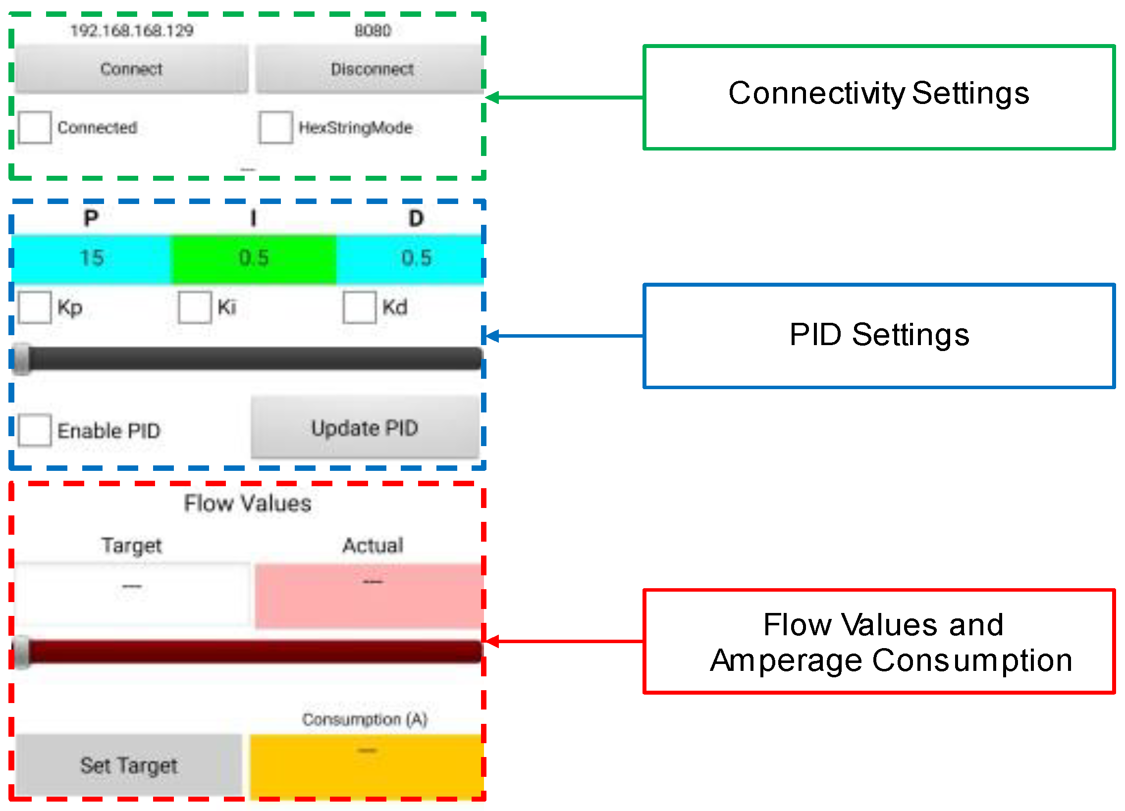
The user (operator) provides via the touch screen of his android tablet/phone device the desired target values for the air flow at a specific distance from the electric fan (i.e., at the point where the flow sensor is put), as well as the control law parameters that define how “aggressive” or “conservative” the motor will be while trying to catch the desired flow level. Indeed, even the whole closed-loop control mechanism can be either enabled or disabled (open loop mode).
These directions (having the form of packetized messages) are passed towards the radio transceiver, at the motor’s end, and consequently are fed to the microcontroller that alters the directions towards the driving modules, according with the given settings. A feedback signal (which is typically the airflow indication value) is used locally by the microcontroller for stabilizing the operation of the fan.
The operator, in turn, gets periodic or on demand notifications/responses from the ventilation system (i.e., from the microcontroller of the motor) on his smart phone through its radio interface. These responses mainly reflect the actual and the target state of the ventilation system.
3.1. Hardware and Software at the Motor’s End
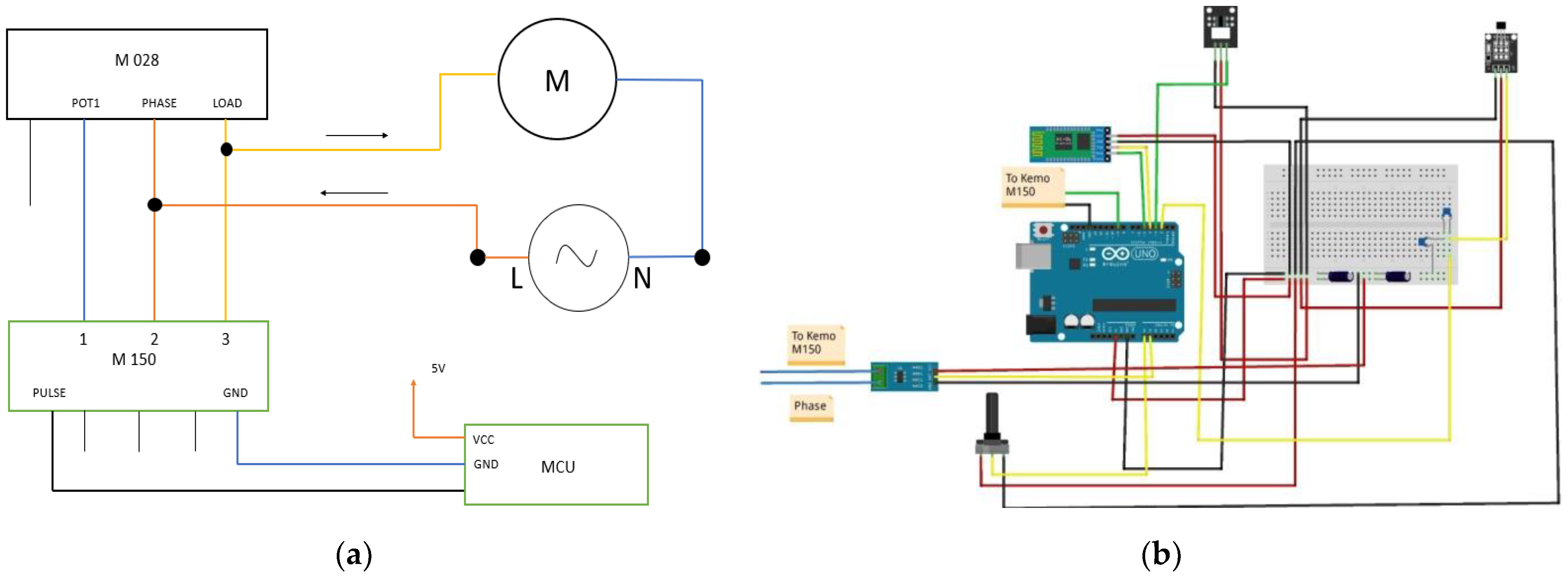
The initial experiments included connection of the Kemo M150 and Kemo M028 modules to a PWM output the Arduino uno unit, to the AC power main and to the electric motor. The blades of the fan were equipped with two neodymium magnets, while a Hall magnetic field sensor was fixed on the body of the motor, near the magnets, so that to generate an electric pulse towards the microcontroller whenever the magnets were passing in front of it. At a second stage, using proper programming via interrupts counting, the rotational speed of the fan was calculated. In parallel, a potentiometer was connected to the analog input of the Arduino providing different PWM levels for testing the operation of the Kemo system. More specifically, the M150 and the M028 modules converted the PWM signals into a suitably modified sinusoidal waveform output feeding the motor (phase control process) thus altering the speed of the electric fan. These speed readings were reported via the Serial Monitor and the Serial Plotter utilities of the Arduino IDE environment.
The hardware arrangements diagram being necessary for the upgrade of the electric ventilator system are depicted in
Figure 2. More specifically,
Figure 2a is dedicated to the wiring of the microcontroller unit (MCU) with the two Kemo modules for efficient AC phase control, while
Figure 2b depicts the detailed diagram (using the Fritzing software) of the components on the Arduino Uno unit (i.e., the MCU), but now with most emphasis to be put on the sensing components.
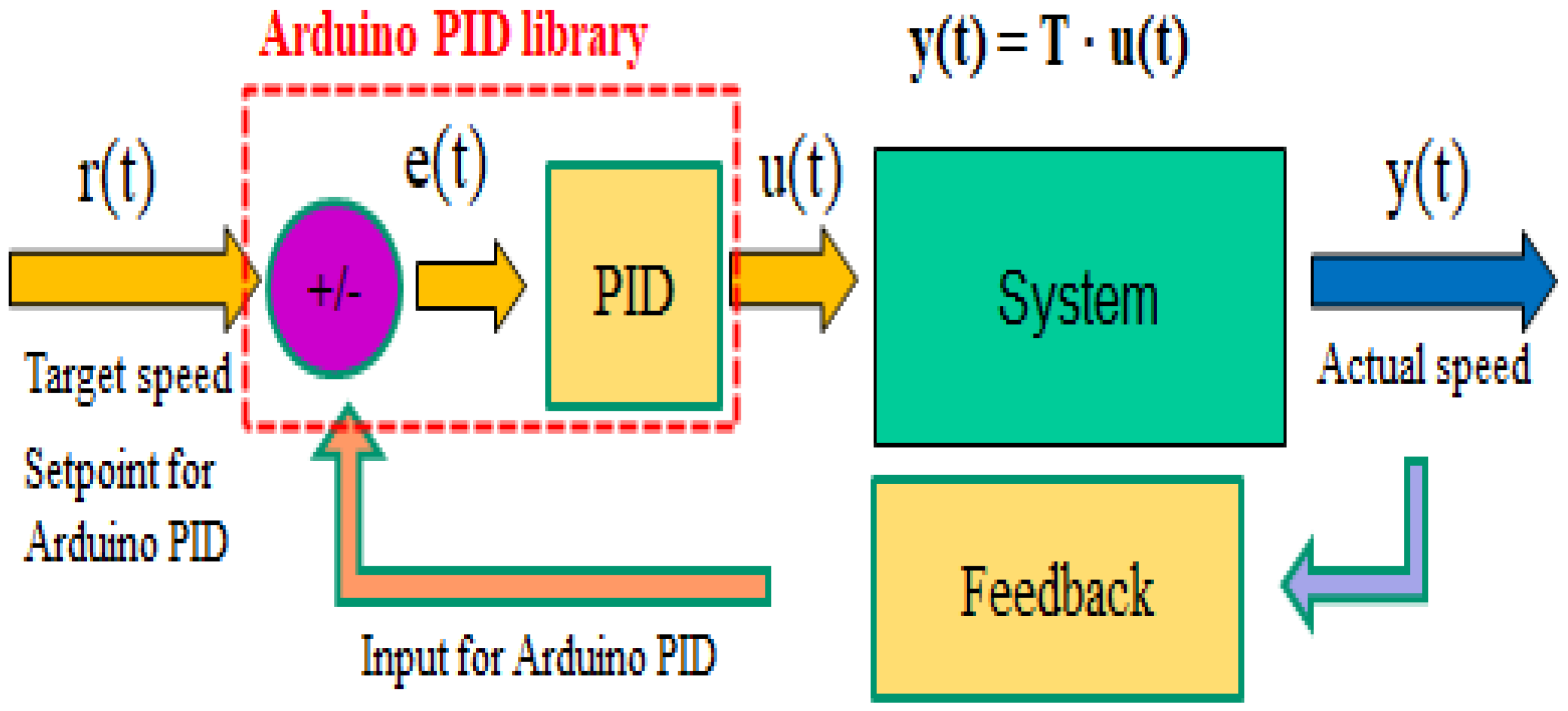
The experience gained through the alternative utilization of the photo interrupter, in lieu of the Hall sensor for rotational speed estimations, was used to create a custom air flow meter. More specifically, an anemometer was constructed using a set of preexistent fins and a photo interrupter for measuring the airflow speed generated by the ventilation fan. The latter custom sensor was acting as an indicative feedback mechanism for a PID controller schema, which was implemented using the corresponding Arduino library [
66], namely the Arduino PID 1.2.0. According to this arrangement, three variables (namely, Input, Output, and Setpoint) were used to implement the automatic control adjustments. These values had to be passed by reference (in C language terminology) to the PID method in order to be immediately updated during the successive iterations of the corresponding algorithm. More specifically, the current output value of the overall system (i.e., the actual airflow speed as measured by the anemometer meter) was used as “Input” for the PID mechanism, the desired (user-defined) output value of the overall system was used as “Setpoint” for it, and the current PWM value to be fed from the Arduino to the motor driver modules was the “Output” for the PID method. These values were taken into account in order to calculate an improved PWM input for the motor driver system, so that the flow of the air to be as close as possible to the desired level. Thus, the Arduino was adjusting the speed of the fan, depending on the target airflow value given by the user and its current value, so that the latter to follow the preferred flow value.
In order to enrich the overall system with remote functionality, the target air speed was given using a smart phone/tablet via a Bluetooth or a Wi-Fi radio connection. Apart from setting the desired target speed/flow value for the operation of the electric fan, the Android smart phone (or tablet) device was utilized for enabling/disabling the entire closed-loop PID control, for easily defining/altering the three critical parameters (i.e., the Proportional—Kp, the Integral—Ki and the Derivative—Kd quantities) of the PID controller, and for remotely inspecting the instantaneous air flow values being achieved during the system’s normal operation, as well as some auxiliary power consumption data using an ACS-712 current metering module (of 5A range) coexisting in the Arduino’s environment. The addition of a simple buzzer installed on the Arduino was a very useful feature in order to confirm that the commands were properly received/intercepted by the system.
The remote monitoring process was achieved by exploiting the phone’s Bluetooth or Wi-Fi radios that perfectly pair with cheap radio modules, either HC-06 Bluetooth or ESP-01 transceivers. The Bluetooth transceiver was easy to install and use, as it was acting as a transparent bridge between the mobile device of the user and the serial port of the Arduino, but was limiting the effective range of the monitoring process to very short distances and only point-to-point connections. For that reason, the alternative implementation that was using the Wi-Fi protocol was also tested. The ESP-01 Wi-Fi module was used in conjunction with the proper ESP module adapter to reduce the wiring complexity.
Figure 3 depicts the main hardware components used for upgrading the actual ventilation system, while
Figure 4 highlights the main functionality of the underlying PID mechanism, implemented on the arduino uno microcontroller.
It must be noted that the software running on the Arduino microcontroller should written so as to be able to perform (almost simultaneously) simple but fast calculations/tasks falling into different time granularity categories:
Intercept the interrupt signals corresponding to the rotating blades of the electric fan and/or the rotation of the anemometer;
Provide PID algorithm correction updates, at a fixed and specific rate, typically between 4 and 10 fan target speed updates per second;
Deliver system status data to the hosting computer via the USB interface or to the operator’s smart phone/tablet, either on demand or automatically on a regular basis;
To accept and respond to (asynchronous) manual commands and parameter changes provided by the user to the electric ventilation motor through the radio interfaces.
As expected, the above tasks had to be performed without blocking or delaying each other to an unwanted degree, constraints that were not easy to be met from the beginning, but later on, more mature code versions managed to achieve it.
3.2. Hardware and Software at the Operator’s End
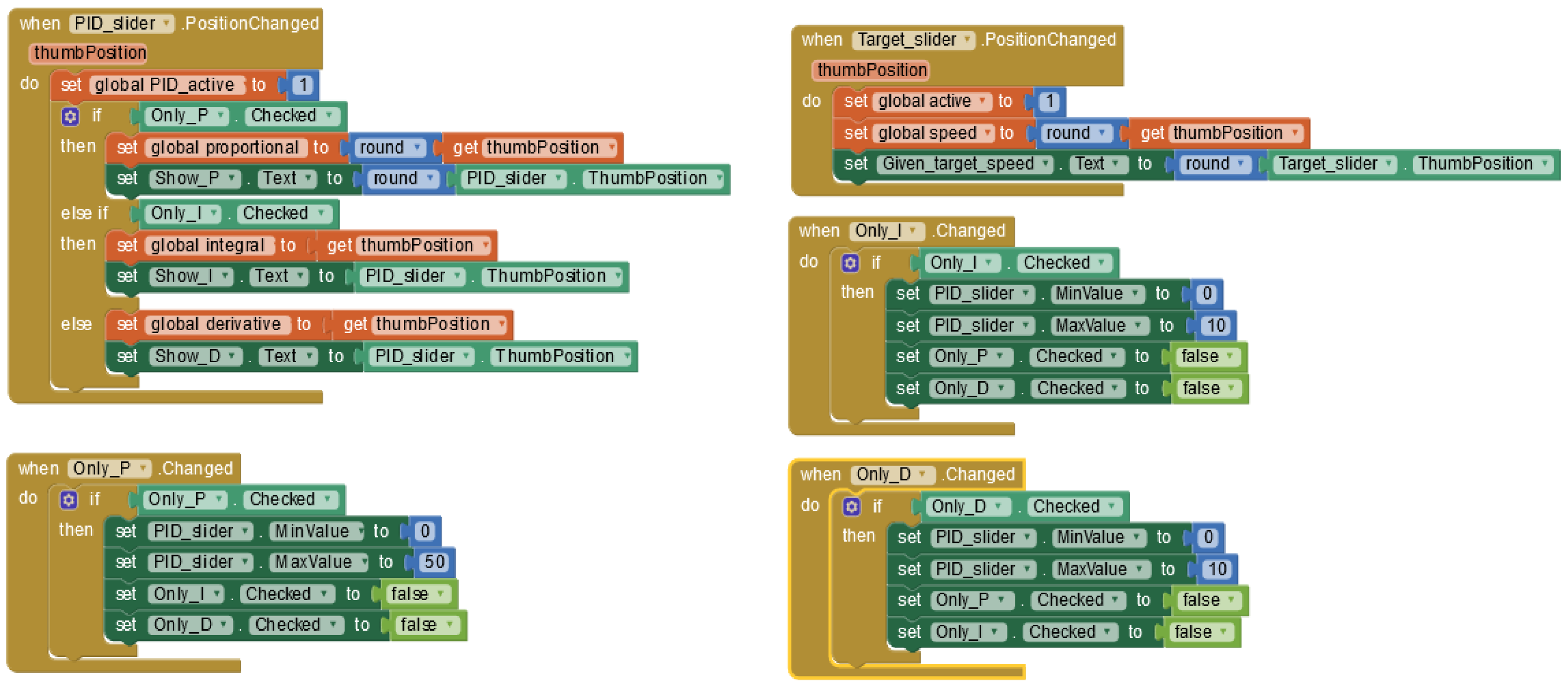
Figure 5 and
Figure 6 highlight the smart phone/tablet application programming details, using the easy-to-use MIT App Inventor environment. Indeed, the MIT App Inventor is an educational visual programming environment that can be utilized in order to create very efficient and easy-to-develop remote interaction mechanisms with embedded devices via Android smart phones/tablets. Depending on the networking method being used, the MIT App Inventor provides special blocks corresponding to functions implementing Bluetooth or Wi-Fi connectivity.
The variant depicted in
Figure 6 was designed for Wi-Fi connectivity case with the ventilation system and thus requires an IP address and a TCP port to be specified. The Wi-Fi solution, compared with the Bluetooth one, provided the necessary freedom for system monitoring operations from increased distances and even from more than one location and/or users. This was due to the TCP/IP nature of the Wi-Fi link with the upgraded ventilation system that supports client-server functionality, can handle multiple connections, and can cooperate with port forwarding mechanisms, in order to guarantee fluent monitoring/management actions from long distances, and/or of more than one system. Nevertheless, this migration from the very simple-to-use Bluetooth module, which is easily supported by the MIT App Inventor, to the ESP-01 Wi-Fi module was not without difficulties, as it is further explained in
Section 3.4.
3.3. Basic Implementation Difficulties
During the implementation of the whole system, there had been difficulties either related with the hardware behavior or with the programming of the ventilation system. Indeed, the realistic dimensions of the whole construction (i.e., its scaled-up character) and the utilization of AC power main instead of low-voltage (and current) DC batteries magnified the potential source of errors. The upgrade process revealed several interference issues that had to be addressed by methods such as using properly shielded cables, by adding 100-nF and 1-μF capacitors in parallel with the sensor’s output and the Arduino’s power supply jack, respectively, or even by selecting a photo interrupter equivalent of the magnetic sensor, fixed near the blades of the ventilation fan. Among these diverse methods, the adoption of shielded cables and capacitors were the most effective ones. These difficulties were not seamlessly bypassed by asking professors’ assistance, on the contrary and intentionally, they were seen as valuable learning opportunities. This section describes some of the most indicative challenges/difficulties of this type during the discussed system upgrade approach.
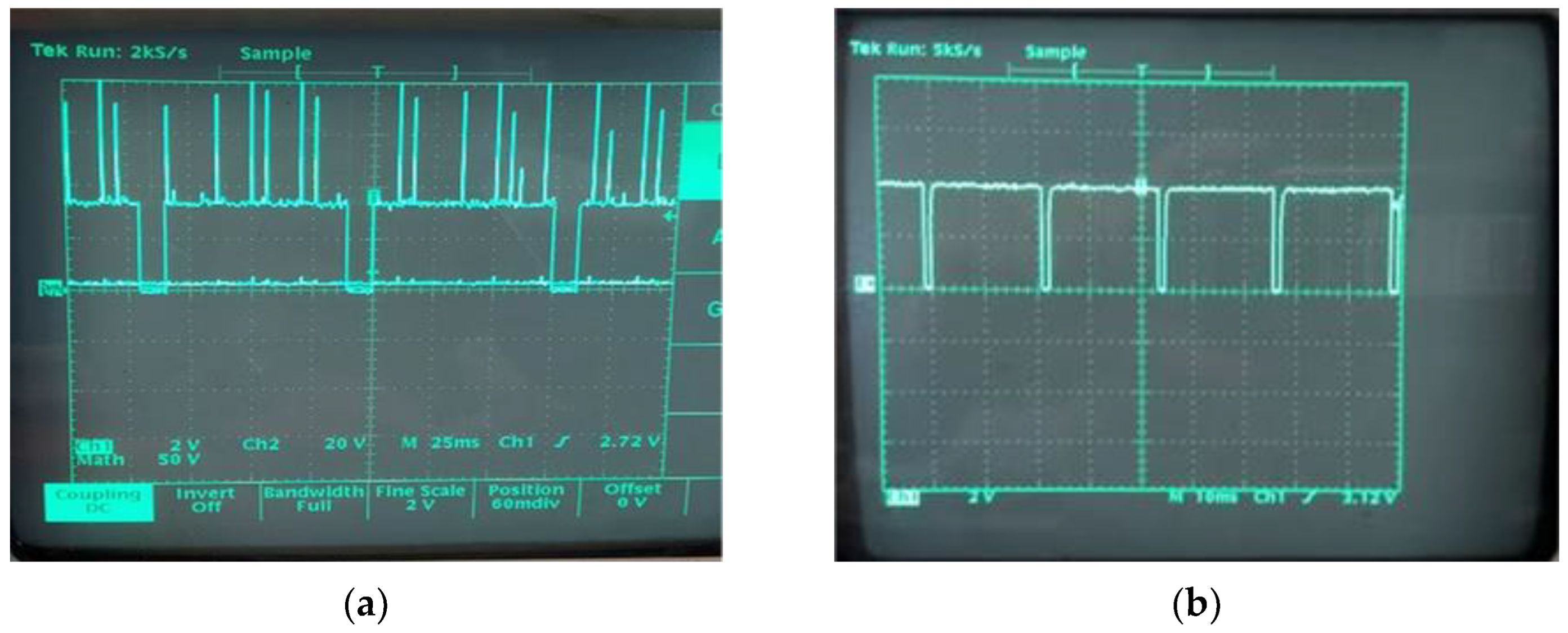
First of all, due to potential interference of fan’s motor magnetic field, the speed measurements, which have been taken when we connected the Kemos with Arduino and fan for the first time, did not correspond to reality, as they were obtained for very high rotational speed values. More specifically, there were many positive peaks above the high level. In order to limit these peaks, a Zener diode was connected between oscilloscope’s channel and microcontroller’s ground.
Figure 7 depicts the Hall sensor output via the oscilloscope’s display before (
Figure 7a) and after (
Figure 7b) limiting the voltage peaks caused by the electromagnetic noise of this type.
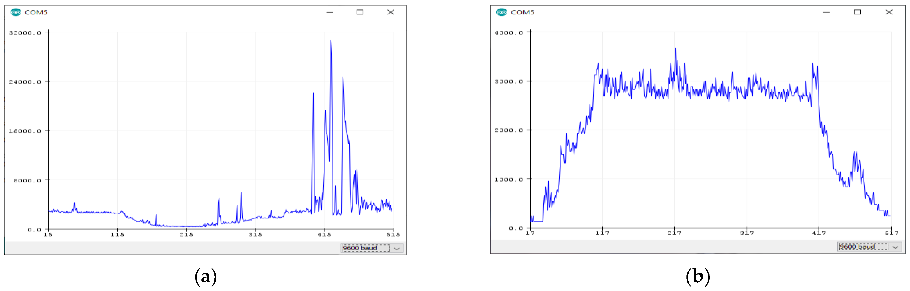
Apart from the classical oscilloscope method, the presence of hardware-assisted software tools, such as the Arduino IDE’s “Serial Monitor” component, help inspect the numerical values of the rotational speed of the electric motor (in rounds per minute—rpm). Furthermore, the “Serial Plotter” component of the Arduino IDE provides real-time graphical inspection of the system’s dynamics by providing speed over time diagrams. Using the latter tool, the most recent 500 points of activity are shown. The Serial Monitor and mainly the Plotter tool were valuable in revealing further imperfections of the ongoing system’s upgrade implementation that the oscilloscope method did not show.
More specifically, despite the limiting effect of the Zener diode that the oscilloscope was verifying, peak-rpm speed values were still shown in the graph that did not correspond to reality.
Figure 8 highlights exactly the motor speed graph before (
Figure 8a) and after (
Figure 8b) the application of a series of improvements described in the following paragraph.
In order to smooth the signal, it was decided to amplify the output of the Hall sensor from 3.3 V to 5 V through a Logic Converter Module. After amplifying the signal, there was the same problem. Moreover, we connected in the circuit two capacitors of 100 nF in-line connection and parallel to the output of the Hall sensor towards the Arduino and another 1-μF capacitor between Arduino’s power supply and the ground. The last intervention improved considerably the quality of the recorded values and better results were achieved by using a shielded signal cable for connecting sensor and Arduino. Finally, it turned out that the most important cause of the problems was not the nature of the magnetic Hall sensor itself but the electromagnetic interference between the motor and the cables connecting the sensor and the Arduino.
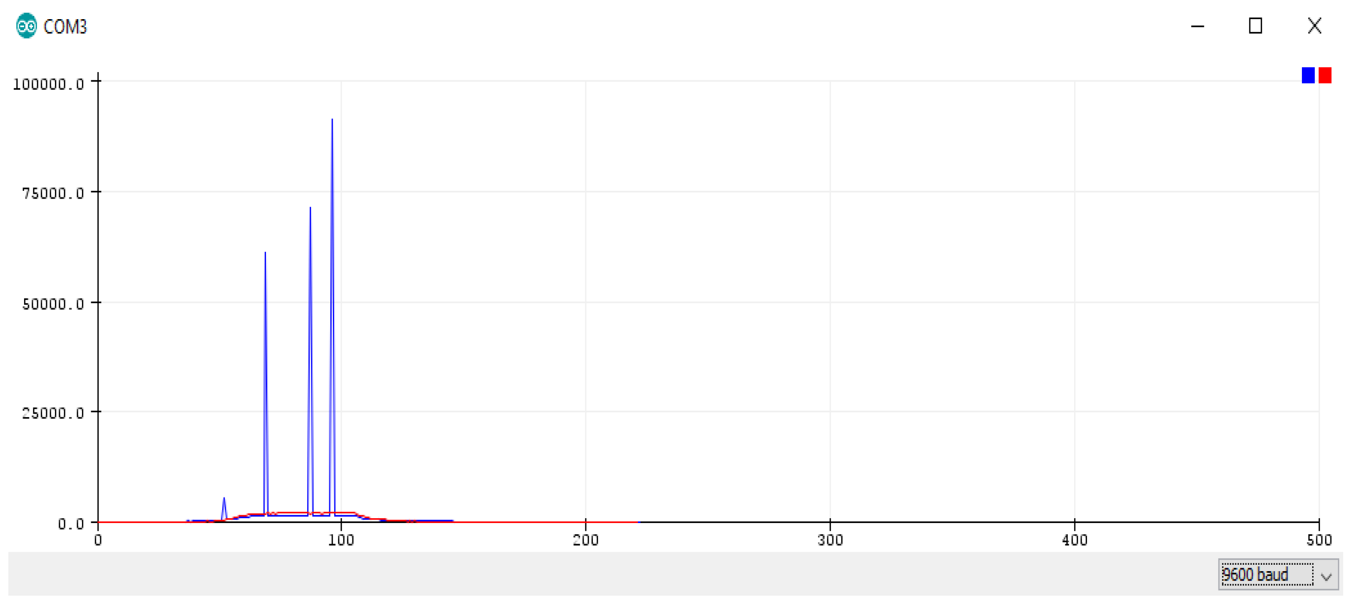
Apart from verifying the importance of using electromagnetically shielded cables for transferring the sensitive signals to the microcontroller unit and of not being too close with the common sources of strong electromagnetic noise (such as motors and power cables), the Serial Plotter tool revealed further imperfections. More specifically, it was ascertained that when the target speed value was altered via the mobile application, the Serial Plotter showed an instantaneous high peak in the speed.
Figure 9 depicts this erratic behavior case. The first reaction towards solving this problem was the electronic part of the project to be transferred to a larger breadboard, leaving more space between the Arduino controller, the Kemo power units, and the radio module, in order to further eliminate potentials interferences, while a larger 10-μF capacitor was added between the Arduino’s power supply and the ground. Unfortunately, none of the above possible improvements provided a solution to the problem and this made the implementation and testing team to seek for software errors.
The reliable hardware-implemented serial port of the Arduino Uno unit was reserved for programing and debugging via the Arduino IDE environment (i.e., its Serial Monitor and Plotter components). For this reason, two general purpose (digital) input/output pins (GPIOs) of the Arduino Uno unit were utilized for communication with the radio module via the typical SoftwareSerial library. The latter library was commonly considered as the “weakest link” and a source of limitations/errors due to its non-optimal design, and thus, more efficient library alternatives were used for bridging the Arduino microcontroller with the radio interface via the GPIO pins. This serial communication library update delivered no results. Thankfully, further inspection of the source code revealed that the target speed value received from the Arduino unit was printed (for debugging purposes) without a space to be left, and thus to be concatenated with the (next) actual value to be shown. This behavior was making the Serial Monitor (and Plotter) to intercept the concatenated values as a single (and very big) actual speed report. After correcting the extra digits in the output values every time, the target value was changed and the system started giving the expected values.
3.4. Discussing Alternatives and Improvements
As explained in
Section 3.1, a custom anemometer was created for measuring the airspeed and providing feedback to the main ventilation system. This feedback mechanism was not the most suitable for a farm premise use, where temperature, humidity and CO
2 metrics would be more valuable, but, from the educational perspective, is the most didactic one as it was providing direct inspection of the system’s dynamic response to external disturbances. More specifically, such airflow disturbances can be caused easily, in a progressive manner, by a student’s hand waving (with caution) between the custom anemometer and the fan’s blades. This way, it is easier to inspect and understand how the underlying automatic control algorithm calculates a better output in order to “catch” the user-provided target airspeed value and makes the whole system more impressive at presentation stage.
The utilization of the user’s android device to monitor/control the ventilation system was guarantying fast and easy experimentation with a wide set of diverse configuration settings. The pairing Bluetooth transceiver was easy to be installed and used, requiring minimal hardware and software effort, but the drawbacks of short communication distances and point-to-point connections provided good reasons for investigating the Wi-Fi radio alternative. Trying to keep the modularity of the upgrade approach as high as possible, and thus not to replace anything but the Bluetooth radio module, the ESP-01 was an apparent alternative. Nevertheless, this transition was not as easy as expected.
More specifically, the operation of the ESP-01 component required proper initialization, via AT commands (such as a typical modem device). Through these commands, a connection with a wireless access point had to be established and a (for instance, fixed) IP address had to be assigned to the radio module, as well as the step of activating a TCP server on the ESP-01 module so that the user’s mobile device to be able to connect on it as a client to the TCP service. Furthermore, as the MIT App Inventor environment was not providing the direct TCP/UDP connectivity interface at the transport layer (while it was supporting HTTP messaging by default), in order to achieve communication between the user’s android tablet/phone device and Wi-Fi module, a specific extension code had to be injected inside the MIT App Inventor project environment [
67].
The programming and the in-parallel inspection/debugging of the basic system were performed via a laptop computer through USB connection. The noisy nature of the working environment near the large AC motor made the participants to adopt a more “comfortable” equivalent solution: a raspberry pi instead of the laptop. Indeed, the Arduino IDE programming environment can be hosted by the linux operating system variant of raspberry pi unit and full remote access to this unit is possible through the Virtual Network Computing (VNC) graphical desktop-sharing, platform-independent system. Thus, the adoption of a raspberry pi single board computer was drastically facilitating the programming of the control and the communication parts being necessary and was providing detailed inspection of the underlying operations. A step beyond that, it was allowing for remote adjustment and monitoring of the ventilation system, literally replacing the ESP-01 module, provided that a simple HTTP or (TCP/UDP) client/server code (written in python language) was enriched with serial reading/writing functionality utilizing the USB connection with the Arduino microcontroller, according to authors’ previous work [
9].
Among the welcome features of the raspberry pi’s engagement in the discussed upgrade project was the fluent log file storage and file (containing data and code) sharing options, e.g., via the WinSCP [
68] utility, as well as the ability to have more than one user connected on it, either locally or remotely, for studying the system’s behavior or for testing different programming alternatives on it. By default, all users connected on the raspberry pi can share the same desktop environment via the VNC, and/or can initiate independent/parallel textual/console connections via the SSH. Although these options were particularly valuable for remote lab activities [
69,
70], they were also very useful for complementing the in situ experiences, where more than one student (and their professors) could work in parallel on the actual system (typically up to four persons), locally connected, typically from a distance of a few meters.
4. Results and Evaluation
The proposed upgraded system has been evaluated from both technical and educational perspective at the university campus, as it consisted a fluent ecosystem for experimentation and learning in actual conditions. As already mentioned in
Section 1, the focus was more on the highlighting the process of combining cheap, of easy-to-find and program components for achieving the functionality upgrade of a realistic system and thus to encourage both hard and soft skills’ acquisition by the participating students. In this regard,
Section 4.1 provides indicative students’ experimentation results with the actual ventilation system being upgraded,
Section 4.2 is dedicated to the evaluation of the overall activity from the educational perspective, while
Section 4.3 provides some additional remarks.
4.1. Experimenting with Basic System’s Behavior
The behavior of the system can be (numerically) inspected and adjusted using the connection with the smart phone/tablet device. Classical electronic measurement instruments, such as multimeters and oscilloscopes, were also available for the students. Furthermore, the USB connection between the Arduino and a computer provided further details of the overall system dynamics. The Serial Monitor and the Serial Plotter components of the Arduino IDE environment were drastically facilitating this process, at no further programming cost.
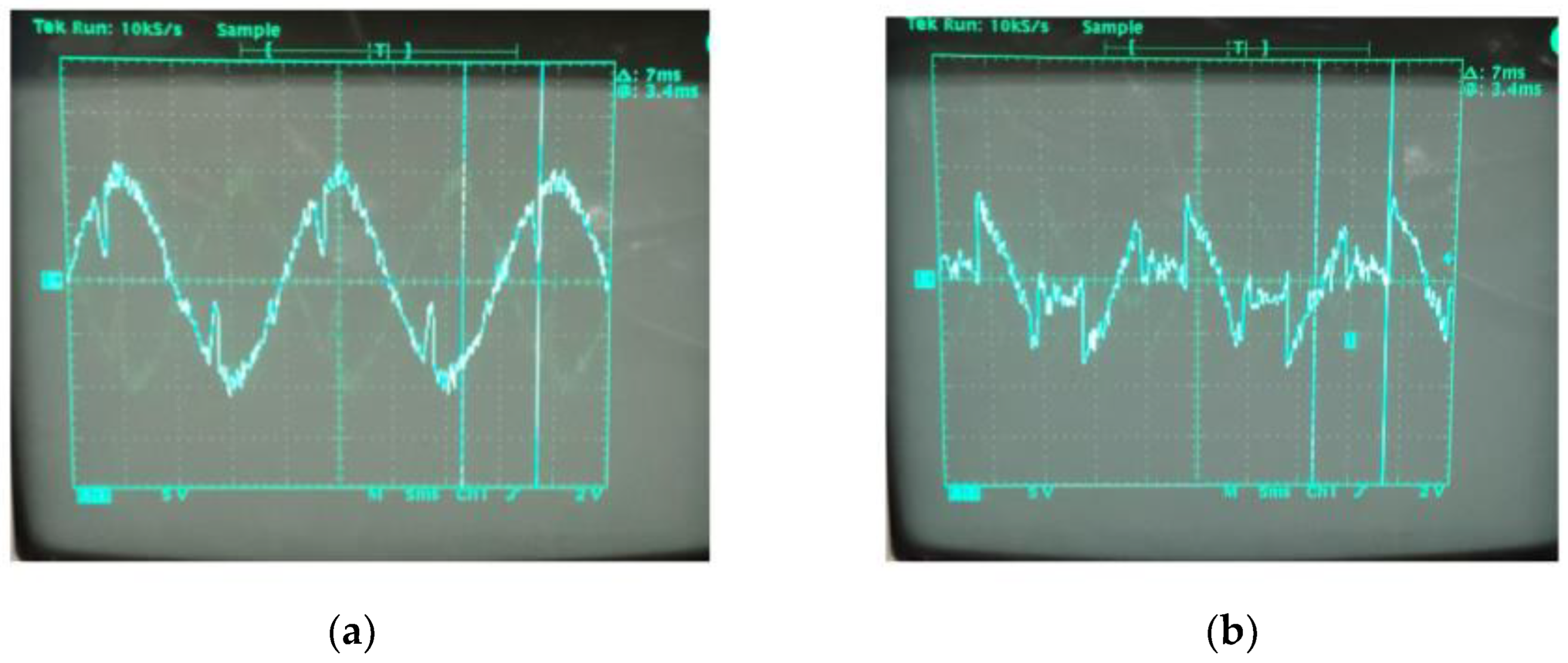
The hiring of an oscilloscope facilitated the study of the effect of the phase control mechanism on the sinusoidal waveform provided by the AC power main before feeding the electric motor. The commands from the user are transformed into PWM signals that make the two-Kemos system to modify the discussed waveform.
Figure 10 shows exactly the output signal from Kemos before its entrance to the motor that rotates faster, if the sinusoid signal is slightly modified (in
Figure 10a), or slower, if the signal is heavily modified (in
Figure 10b).
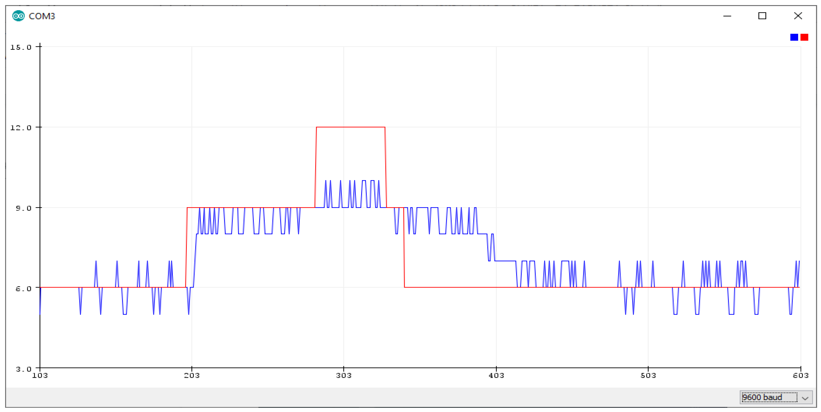
The Serial Monitor component can visualize both target and actual airflow quantities, provided that a pair of such values (separated by space) are written to the serial interface of the Arduino Uno towards the USB port of the pairing computer. The red line corresponds to the target value of the airspeed (provided to the Arduino via the smart phone/tablet) and the blue line corresponds to the actual speed of flow generated by the fan, in response to the target directions, as measured at the point where the custom anemometer is. The latter visualization of the dynamic behavior of the control system being implemented is depicted in
Figure 11, where the desired flow level (red line) is altered by the user. For simplicity reasons, both target and actual airflow values are expressed in relative scale and arbitrary units.
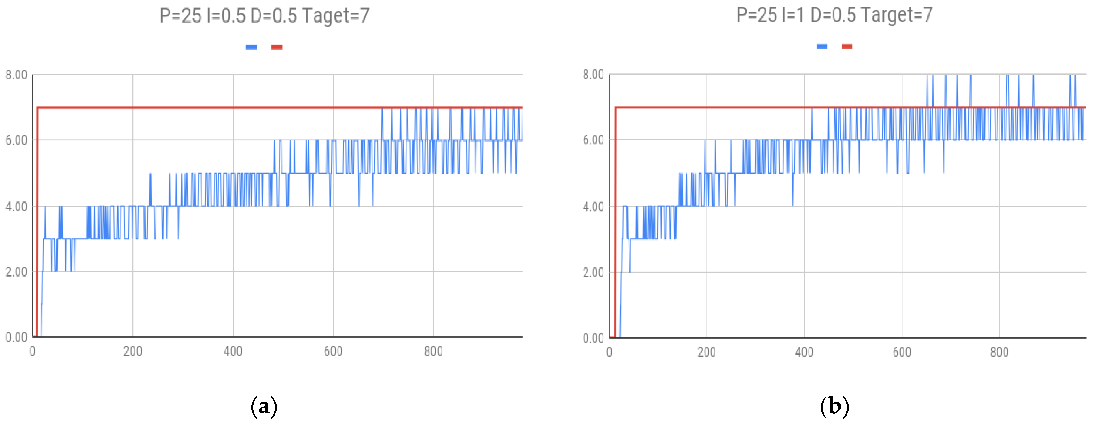
Focusing on the step response behavior of the ventilation system for different PID (i.e., Kp, Ki, and Kd parameters), further experiments were conducted.
Figure 12 depicts the corresponding results now generated using post processing of the values being gathered. The differences compared with the results provided by the Serial Plotter tool are negligible except the cost of the post processing itself for the humans. The case in
Figure 12a corresponds to parameter selection of 25, 0.5 and 0.5, for the Kp, Ki, and Kd quantities, respectively. The case in
Figure 12b corresponds to parameter selection of 25, 1.0 and 0.5, for the Kp, Ki, and Kd quantities, respectively, and thus, the rising (and the settling) time is shorter (i.e., faster response) compared with the previous case, as the increased value of the Ki parameter results in a more aggressive behavior. All values are expressed in arbitrary units as well.
The cases explained herein are the most characteristic for introducing and studying the idiosyncracies of a simple automatic control system, such as the proposed one, and also better highlight and reveal the ability to handle comparatively large inductive loads (i.e., motors) of AC type, in contrast to many similar educational approaches that are limited to/concentrate on small DC-powered motor modules or virtual environments.
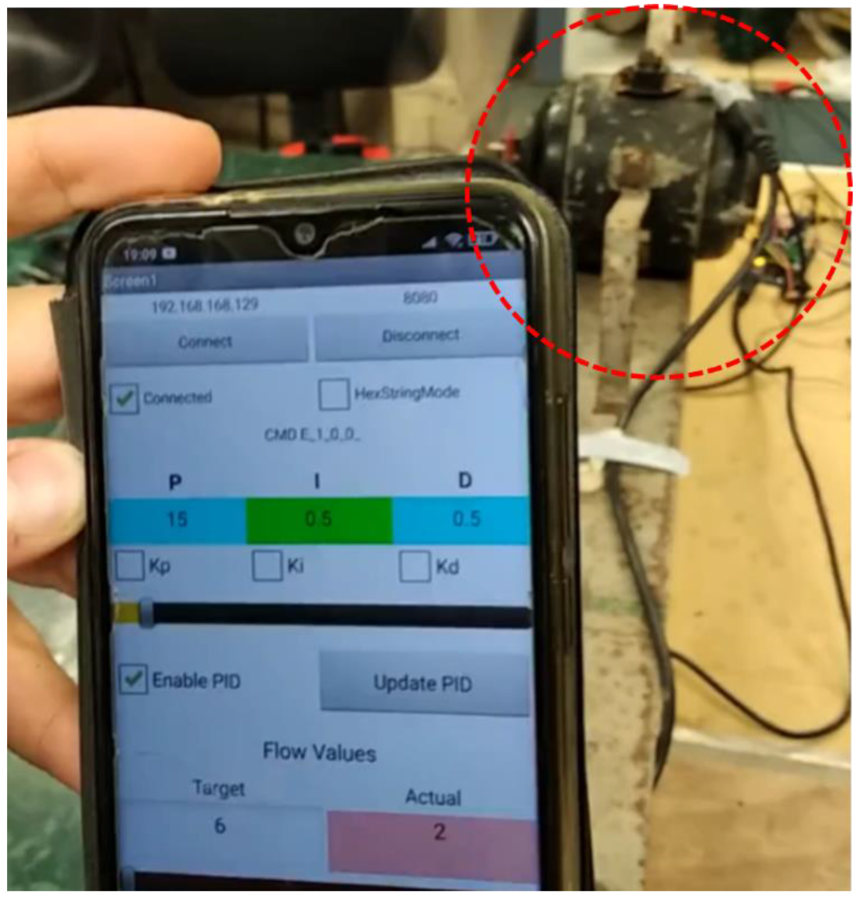
The behavior of the communication/user interaction part is more obvious as the students, being very familiar with the smart phone/tablet devices, were acquainted quite easily with the control functionality variants being implemented and performed several experiments using diverse settings. Most of them were performed from a distance of a few meters from the actual system under testing.
Figure 13 depicts exactly students’ experimentation with the mobile application for adjusting and monitoring the operation of the ventilation system.
It took about 8 months, in two university semesters, to complete the whole project, of which 4 months were for the basic version, 3 for the improvements and the last for the complete documentation. In terms of finance, the overall cost of the basic implementation did not exceed the 100 € limit, as it is explained in
Table 1 (with the fan module to be a pre-existent one and thus its minimal estimated cost to be subtracted from this budget). The involvement of a raspberry pi unit with the accompanying microSD card and cables, instead of a laptop, would add another 50 €, approximately.
4.2. Educational Impact
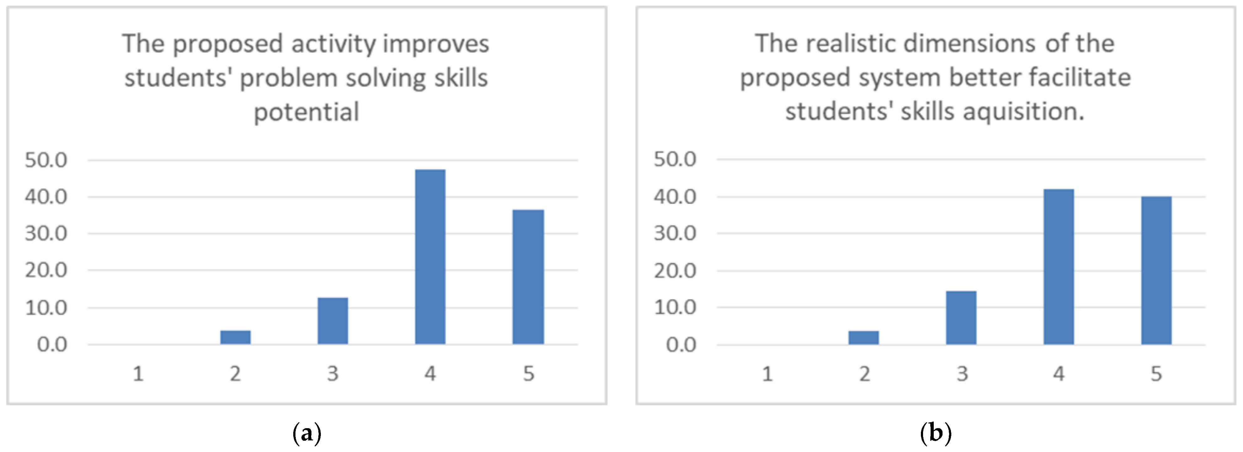
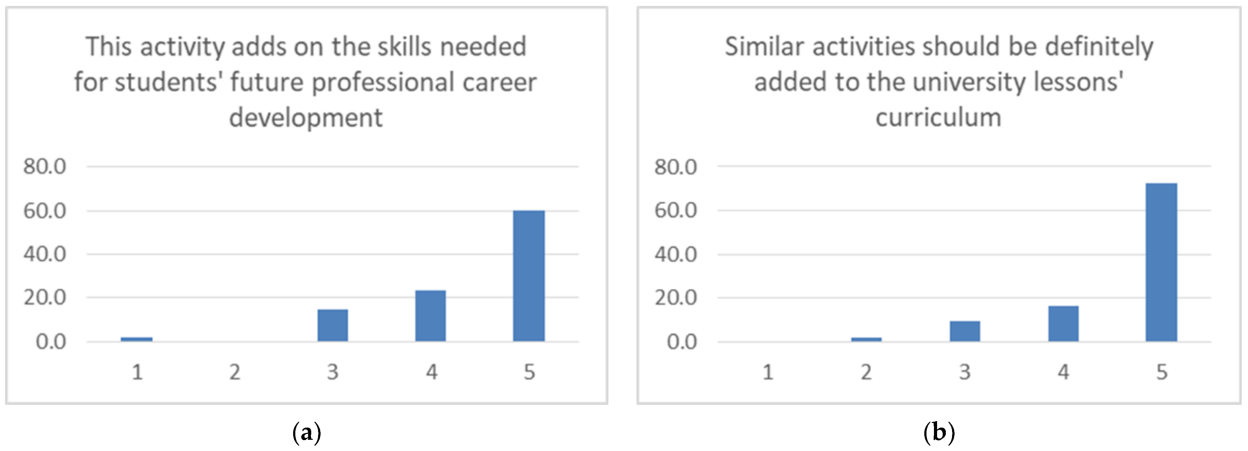
The persons involved in the design, modification, implementation, and/or testing stages of the proposed platform, were both university students and their professors (the latter, 3 to 4 persons in total). These persons (55 persons in total) where interrogated, anonymously and with their consent, through interviews and Likert-scale questions, in order to assess the whole process. The engagement of the students in these activities varied from an entry-level to an expert-level degree, according to their participation in either curricular or extracurricular university activities, both targeted in the STEM area, for the specified eight-month period of their studies. An indicative set of the early results being collected and processed is depicted in
Figure 14,
Figure 15,
Figure 16,
Figure 17,
Figure 18,
Figure 19 and
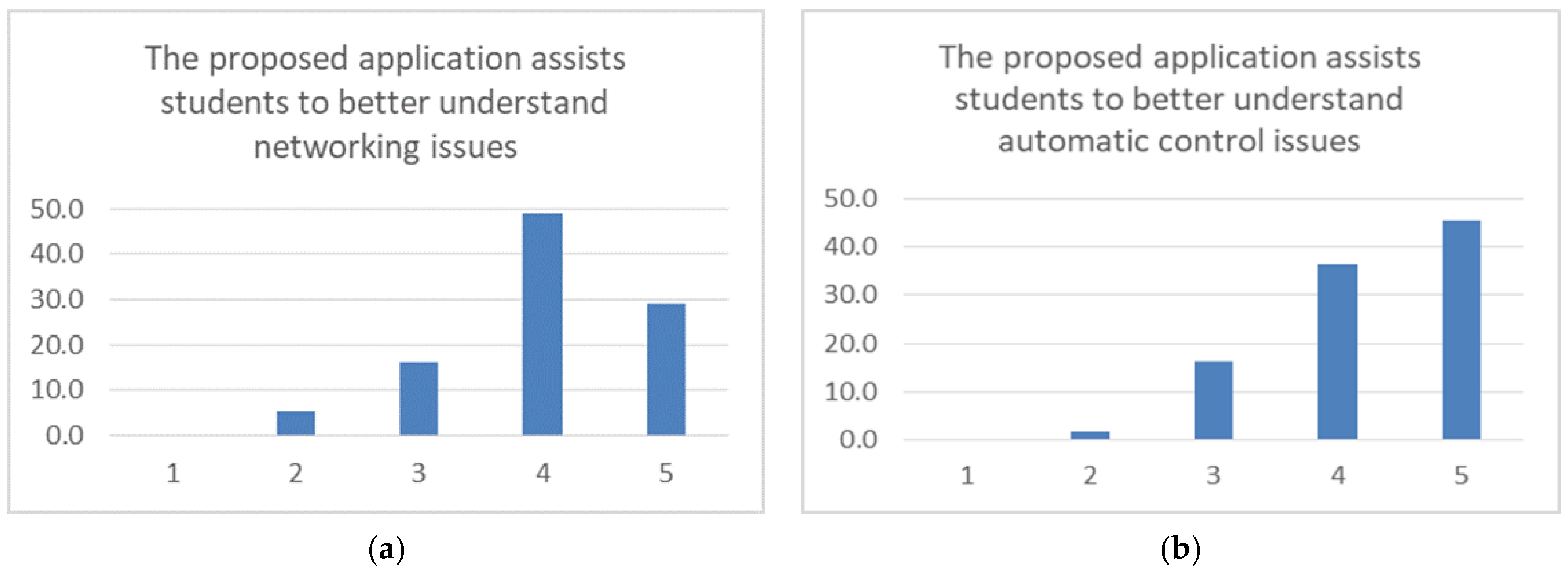
Figure 20. In all these figures, the height of each bar (vertical axis) expresses the percentage of people having a specific degree of positive or negative opinion about the question (sometimes shortened) depicted above the chart. The horizontal axis contains bar (opinion group) characterization, by a number from 1 to 5, where 1 means “Strongly Disagree”, 2 means “Disagree”, 3 means “Undecided”, 4 means “Agree”, and 5 means “Strongly Agree”. The exact statements used in the evaluation forms of this survey are given in
Appendix A (in
Table A1), while means for each statement are provided in the right column, to directly summarize participants’ opinions, according to the corresponding five-point Likert-scale score.
In all cases, the setup remained as open and cost effective as possible, to maximize the reusability of components and to exhibit high modularity, thus allowing for several educationally meaningful checkpoints [
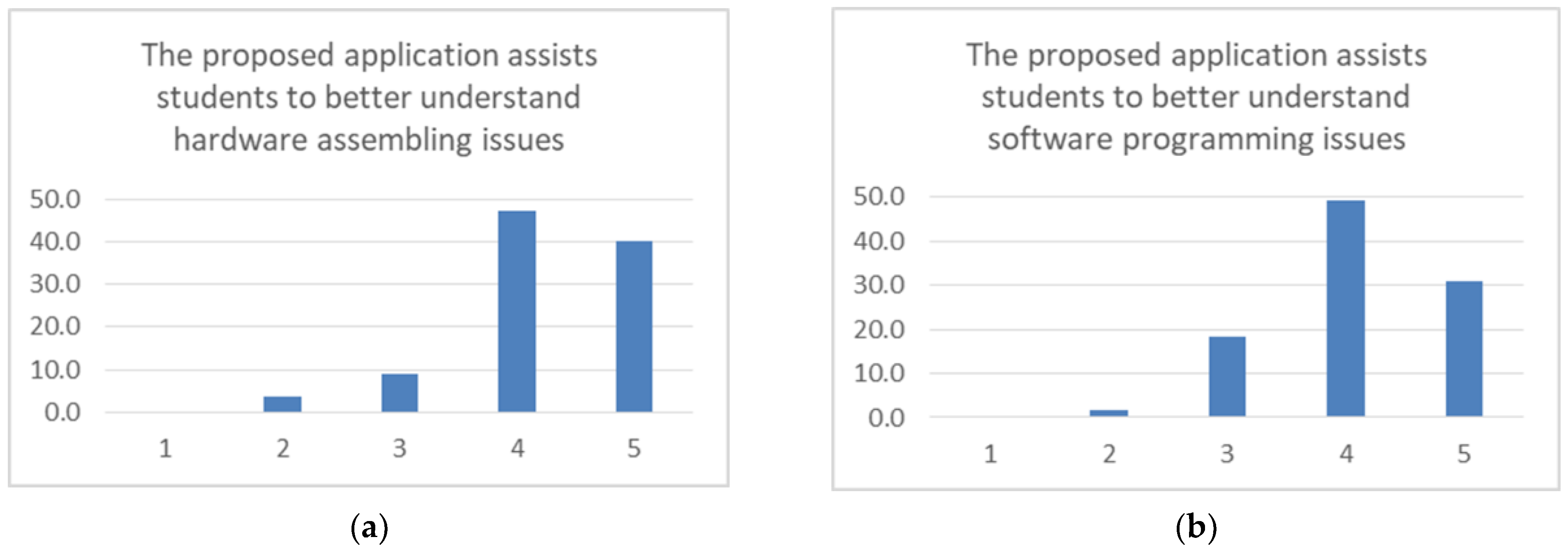
9]. The modular nature of the overall upgrade design of the farm ventilation system, as well as the tools hired for assembling, programming, connecting, inspecting and controlling it, allowed for parallel implementation steps, highlighted the idiosyncracies of each separate component and facilitated the understanding of the contribution of the discussed activity to the university lessons’ curriculum update. More specifically, the survey results clearly indicate that the engagement in the whole process was beneficial for understanding fundamental hardware assembling and software programming topics (
Figure 14a,b, respectively). Moreover, the respondents found that the proposed activity was helpful to better understand networking topics (
Figure 15a) and automatic control fundamentals (
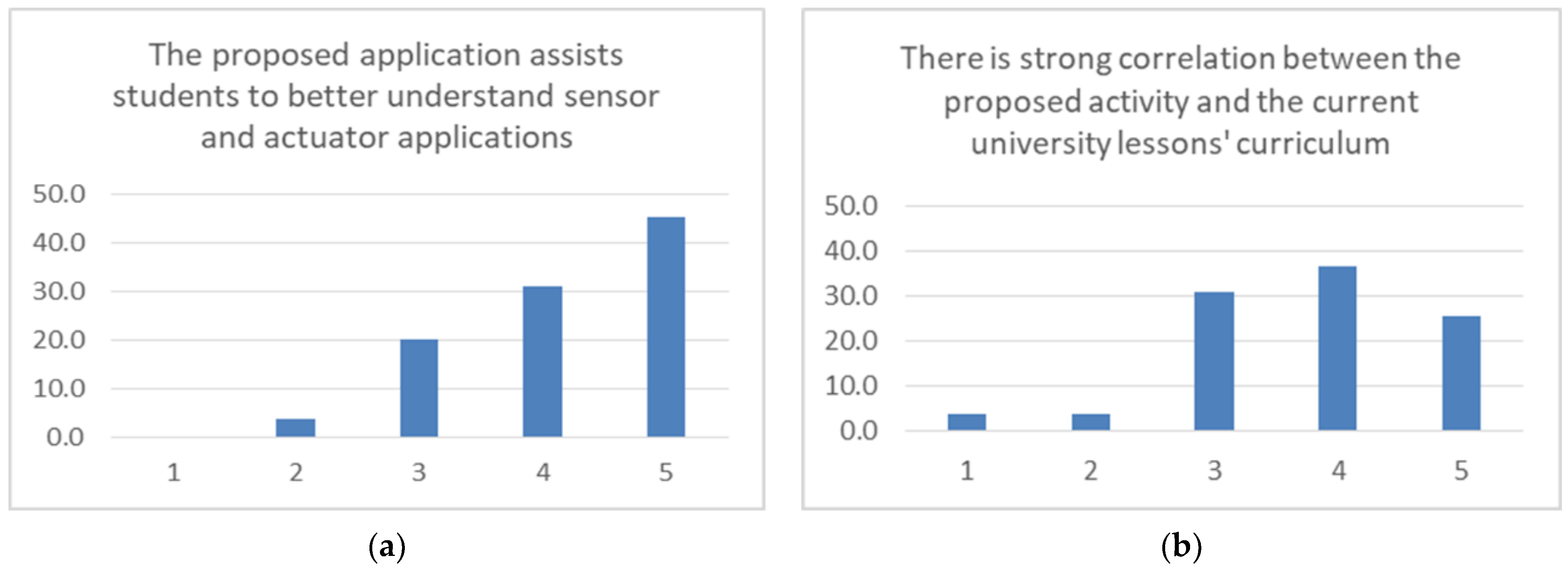
Figure 15b). Similarly, participants’ opinions about the contribution of the proposed activity to understand the role of sensors and actuators were very positive (
Figure 16a). The correlation of the proposed activity with the current university lessons’ curriculum of the participating persons was high (
Figure 16b), which is justified by the meticulous educational design of the specific pilot upgrade project, but there is space for further improvements in the curricula, as indicated by the mean score of 3.76, which is the only one below the 4.00 limit in this survey.
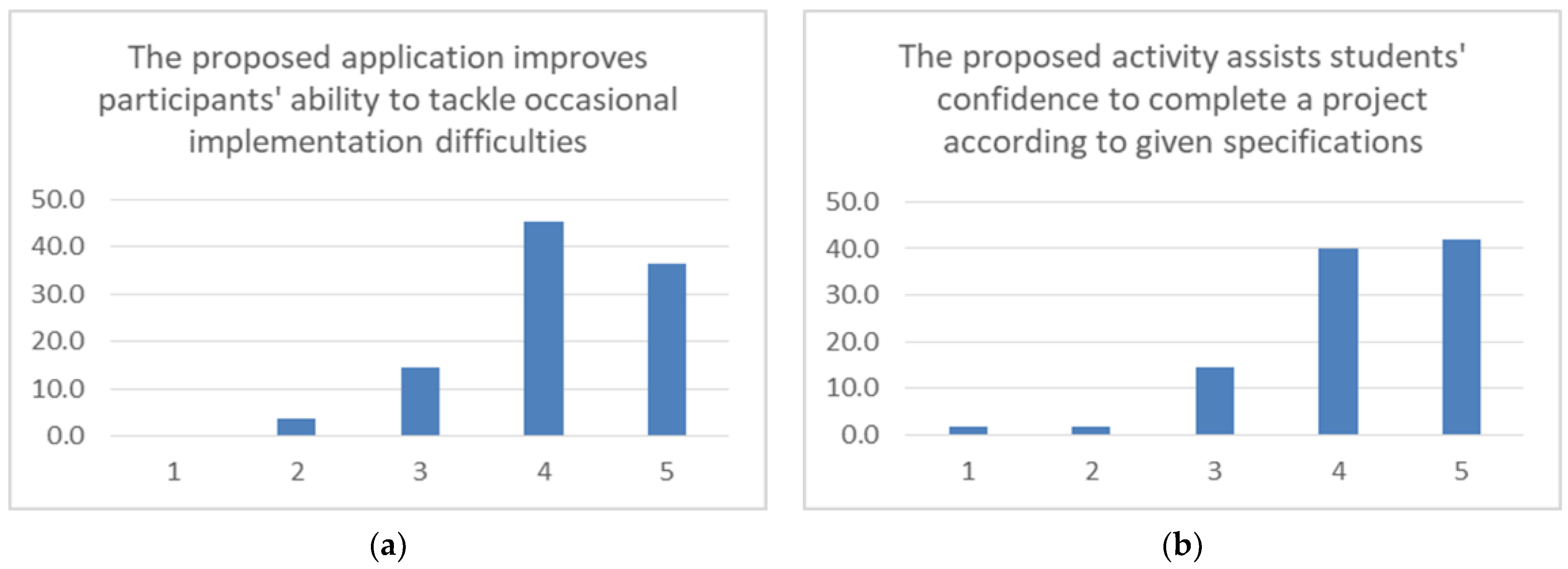
It is worth mentioning that the meticulous hardware and software settings of the project were functioning as magnifying lens for studying the ongoing upgrade process challenges. Indeed, according to the feedback provided by the responders, the occasional difficulties during the implementation stages were seen as valuable learning opportunities that had to be exploited to a maximum (
Figure 17a), thus improving participants’ potential to complete a project, according to the given specifications (
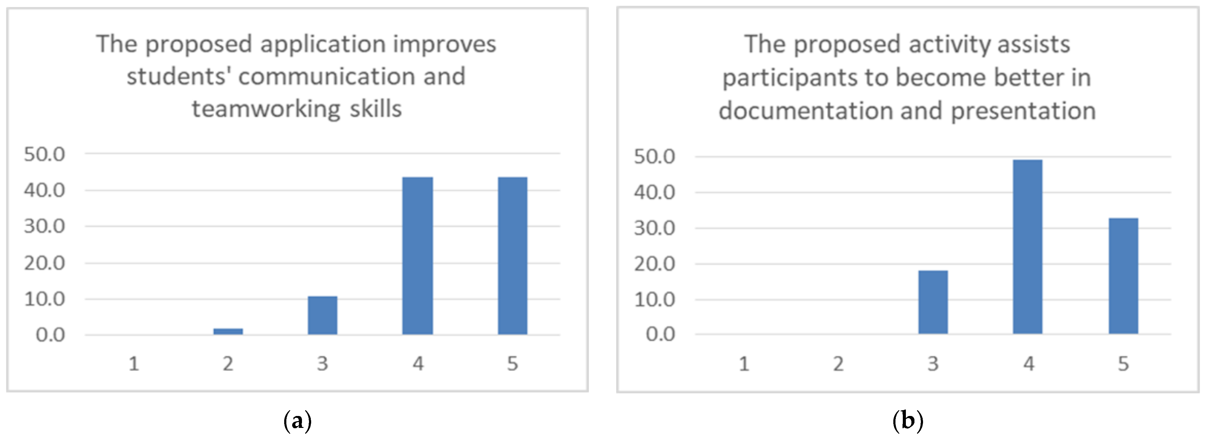
Figure 17b). Furthermore, participants improved their communication and teamworking skills (
Figure 18a) and became better in documenting and presenting their work (
Figure 18b). Of key importance for the latter achievements, apart from the arduino programming community paradigm, was the contribution of the MIT App Inventor cloud-based environment that allows for fast prototyping and code sharing, as well as the raspberry pi unit that favors multiple sessions for programming and inspecting the embedded system’s behavior. The complementarity of the tasks being assigned to the students and the fluent opportunities for direct interaction with and inspection of the system under construction were further triggering the teamworking spirit. As explained in
Figure 19a, participants became better in problem solving and the fact that they had to deal with a scaled-up system of realistic size, instead of a miniature but yet education-oriented implementation such as the one presented in [
23] (an implementation variant that many of them were familiar with), served more effectively the valuable skills acquisition process (
Figure 19b).
Finally, it became apparent that the participants believed that the proposed activity was further triggering students’ interests and attributes to the skills needed for their future professional careers (
Figure 20a) and that activities including similar topics and tasks should be incorporated in the university lessons’ curriculum more drastically (
Figure 20b). The responses to the last two statements achieved the best score, having a mean of 4.40 and 4.60, respectively.
The proposed approach was tailored to better introduce to and communicate among the students the fundamentals of automatic control, a process which is of dominant importance for many processes of agricultural character, and is also directly linked with other modern technological practices of the digital era, such as networking and sensing. The results verify that the specific system upgrade activity had an educational impact better than a smaller one in size, while it was efficiently tailored to the student needs, in contrast to solutions being too generic or too composite or less open to connectivity and experimentation variants, such as a commercial PLC system.
It must be noted that, although there are studies comparing the effects of using robotics in elementary and secondary schools, there are less empirical studies on the real effect of applying robotics in higher education [
55]. Furthermore, recent analysis of the literature and the situation in monitoring and managing in the agriculture and ecology field, indicated that there are few special education courses regarding these issues [
71]. These remarks make the contribution of the proposed approach even more beneficial for the research community.
These results being presented are completely in-line with and extend previous educational findings in the area [
9,
55,
72], while they serve the objectives of agri-food professionals engaged in the transition towards sustainable agriculture. Indeed, according to the study presented in [
73], the future professionals need skills that encourage a perspective that builds on heterogeneity and inclusion of different knowledge, practices, and experiences, and the ability to respond and be proactive in a constantly changing world.
4.3. Further Discussion
During the activities being discussed, the role of the professors was remaining discrete and encouraging. In most cases, they were present for providing guidance and advise if they were asked to. This policy was mainly being followed during the extracurricular part of the project. During the laboratory/classroom lessons, professors also tried to trigger student’s interests by introducing the topics in a progressive manner (in terms of complexity) and by being rewarding against the students’ everyday progress. The role of the more experienced students, acting as mentors and multipliers, was of a catalytic importance as well. The positive attitude against the various technical difficulties of the actual farm equipment upgrade process, was the best performing paradigm for further creativity and improvement.
The functionality being offered could have been implemented in a more compact manner using WeMos or ESP32 modules, thus replacing completely the Arduino unit and the ESP-01 modules, but this would be translated in reduced modularity, increased configuration changes and complexity beyond the didactic objectives of this study. For the same reason, the role of the powerful raspberry pi unit was kept quite conservative as well, although it could also have replaced entirely the Arduino Uno and ESP-01 pair, accompanied by some suitable but cheap peripherals. Nevertheless, since the basic system allows for TCP/IP connectivity, it can be combined with Virtual Private Networks—VPN and/or port forwarding mechanisms to provide remote management, by multiple users, via the Internet. Indeed, the rapid progress of the telecommunication technologies allows for several new perspectives in the agricultural sector [
74]. Under these circumstances, the coexistence with a Raspberry Pi unit is the favorable option, as the corresponding network services, as well as cameras and microphones can be easily installed on it.
It must be noted that the hardware and software arrangements being described are generic, and thus, they can also be applied to other premises of agricultural and educational interest, such as pumping systems or greenhouse shading systems. This can be achieved by keeping the same logic and wiring, as in the arrangement being presented, and just replacing the electric fan (actuator) module with a pump or an electromechanical shading unit and installing the suitable sensors.
Willing to scale up further, the proposed configuration could support event larger motor fan modules and also more composite system surroundings, as, for instance, more accurate and diverse sensors, according to the final installation preferences and budget. Indeed, this upgraded system could contain expensive equipment of industrial specifications, to capture temperature, humidity, air quality and gas concentration, thus resulting in monitoring and adjusting the ambient environmental conditions more accurately and effectively via the user’s mobile device. In the modern IoT era, and for fluent remote monitoring and control, further technologies and architectures are available, aside the native TCP/IP one, such as LoRa, ZigBee or NB-IoT. Apparently, the discussed ventilation system, if equipped with different radio modules, could be an end node in such an infrastructure. Nevertheless, in all cases, the limit between serving the various educational priorities at the universities and delivering turn-key solutions of commercial standards should be very carefully defined.
5. Conclusions
This paper tried to highlight the intrinsic details and challenges of making the necessary adaptations to a retired, ready-for-scrap, ventilation fan module from an agricultural premise, so as to convert it into a full-size, auto-adjustable and remotely controlled (via a smart phone or tablet device) system, which was suitable for educational purposes. A small arduino unit, a typical AC power control module, a few cheap sensors, and a wireless transceiver were enough for realizing the basic variant of the discussed upgrade. The role of the necessary, free to access and use, software programming environments (both visual and textual), was also very important and could not be overlooked. In all cases, the setup intended to remain as open, modular and cost effective as possible, to maximize the reusability of components and to allow for several educationally meaningful check points. The enhanced system was capable for easily studying the impact of the diverse PID controller settings, a fundamental engineering task included in most technical university lessons’ curriculum. Several hardware assembling, software programming and networking skills were acquired as well. As expected, larger implementations are quite impressive and inspiring while operating but also magnify any potential cause of malfunction, thus validating the whole Murphy’s laws list. The case described herein was not an exception, but this fact made the whole process very didactic for persons getting involved.
Future plans include further system’s enhancements using similar inexpensive components and additional implementation of other constructions following the same low-cost upgrading policy. The motive for that is to provide experimentation with a wider variety of real-world cases that students of today and future professionals will have to tackle in their careers.


 ,
, 

