Article

Postwall-Slotline Stepped Impedance Resonator and Its Application to Bandpass Filter with Improved Upper Stopband

State Key Laboratory of Millimeter Waves, Southeast University, Nanjing 210096, China
*
Author to whom correspondence should be addressed.
Electronics 2022, 11(6), 851; https://doi.org/10.3390/electronics11060851
Submission received: 24 January 2022 / Revised: 24 February 2022 / Accepted: 7 March 2022 / Published: 9 March 2022
(This article belongs to the Section Microwave and Wireless Communications)

Abstract

:
In this letter, a postwall-slotline stepped impedance resonator (PWS-SIR) is proposed and applied to a bandpass filter (BPF) with a wide stopband. The proposed PWS-SIR-BPF comprises three U-shaped PWS-SIRs and two microstrip-slot feeding transitions. A PWS has a much lower impendence which a conventional slotline (CSL) cannot reach, so a much smaller impendence ratio of the PWS-SIR can be achieved. Consequently, a wider stopband simultaneously can be realized for the proposed filter. The designed PWS-SIR-BPF, as well as a CSL-BPF, have been fabricated, measured, and compared to verify the features of the PWS-SIR. The measured results are consistent with the simulation ones. The PWS-SIR is 7.3 mm (0.22λ0) long, 67% of 11.1 mm (0.34λ0) of the CSL resonator. The first spurious resonance frequency of the PWS-SIR-BPF is extended from 9.8 GHz (2f0) to 23 GHz (4.7f0).

1. Introduction

A slotline is often used in a filter as either a coupling component or resonator. As resonators, a slotline bandpass filter (BPF) has been widely applied in modern wireless communication systems [1,2,3,4,5,6,7,8,9]. Due to high-order resonant modes, a simple uniform slotline BPF has the first parasitic passband at 2f0 (the center working frequency), which will narrow the upper stopband of the BPF. Therefore, a slotline BPF with a wide upper stopband is highly desired.
There are usually two ways to expand the upper stopband of a slotline BPF. The first is to use a slotline resonator with a loading strip/slot, and the upper limit of its upper stopband is 3f0 [6,7]. The second is to use a stepped impedance resonator (SIR) in a filter, and the upper limit of its upper stopband could be much larger than 3f0. Therefore, Various BPFs use SIRs [10,11,12,13,14,15,16,17,18,19,20], including slotline BPF [10,11]. The lower the impedance ratio of SIR is, the smaller the size is, and the wider the stopband is. The characteristic impedance of a conventional slotline (CSL) is usually large. When the slot width changes, the span of the characteristic impedance is narrow due to its structure feature. Therefore, it is difficult to achieve a CSL-SIR with a low impedance ratio.
In this study, a postwall-slotline stepped impedance resonator (PWS-SIR) is proposed and applied to a BPF with a wide stopband. The PWS-SIR consists of a high-impedance CSL and a low-impedance postwall-slotline (PWS). Due to a very low impendence of a PWS [21], the proposed PWS-SIR can achieve a low impendence ratio with a small size. Thus, the features of compact and wide stopband of the SIR-BPF are achieved with PWS-SIR. A PWS-SIR-BPF, as well as its counterpart, a CSL-BPF, have been designed, fabricated, and measured. Compared to the CSL-BPF, the PWS-SIR-BPF has a wider upper stopband up to 4.7f0 and a compacter size. In addition, it also has a better rectangular factor and selectivity.

2. Filter Design

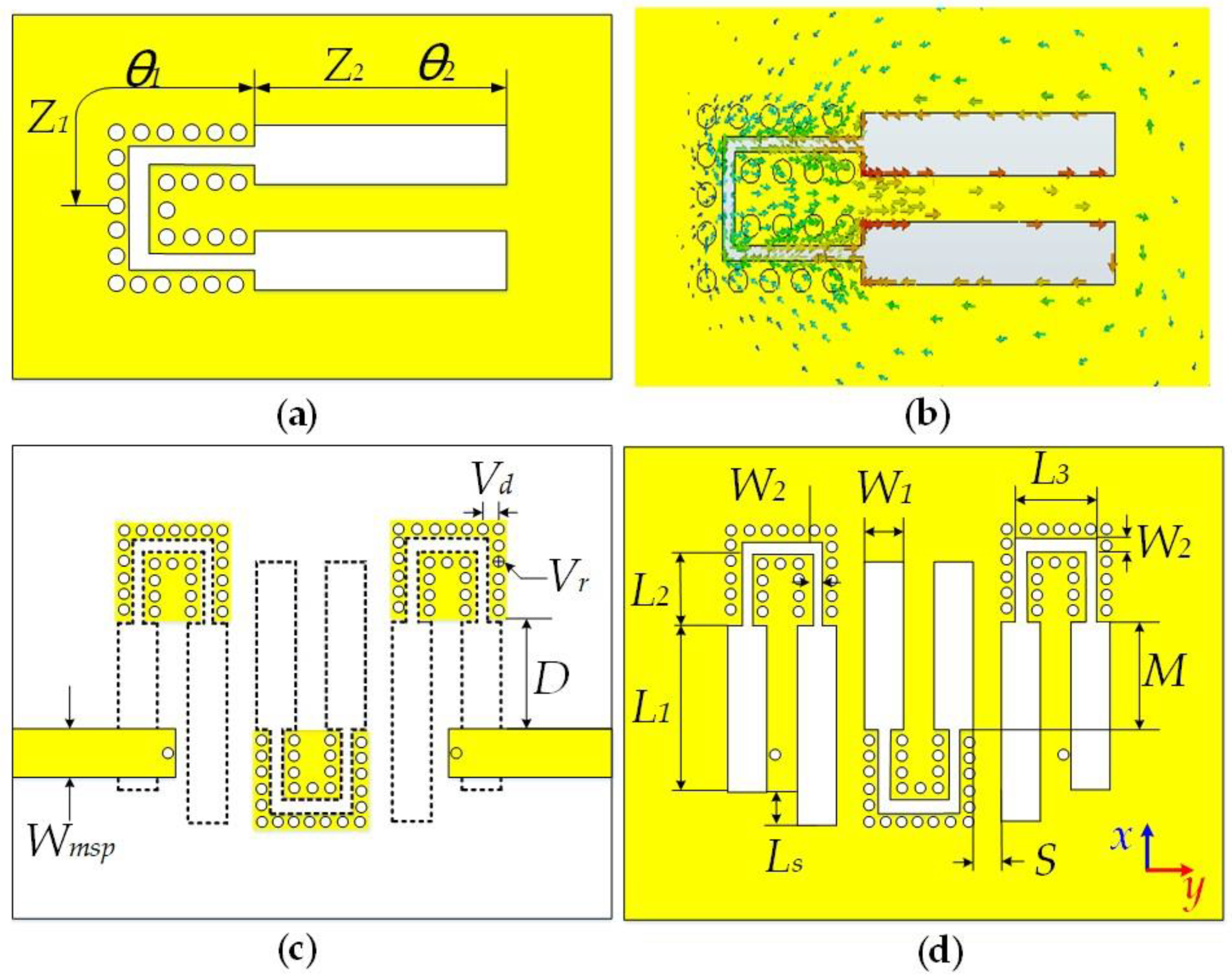
2.1. Filter Structure

Figure 1 presents the proposed BPF on a two-layer printed circuit board fed by a microstrip-slot structure. Three U-shaped PWS-SIRs are printed on both sides of the substrate, and two microstrip lines are placed on the top layer for feeding, as shown in Figure 1c,d. PWS is a slot-based transmission line with two rows of metalized via connecting the top strip and bottom plane on either side of CSL [21]. The high impendence portion of the PWS-SIR, as shown in Figure 1a, is a CSL with a 2 mm slot width, and the low impendence portion is a PWS with a 0.2 mm slot width.

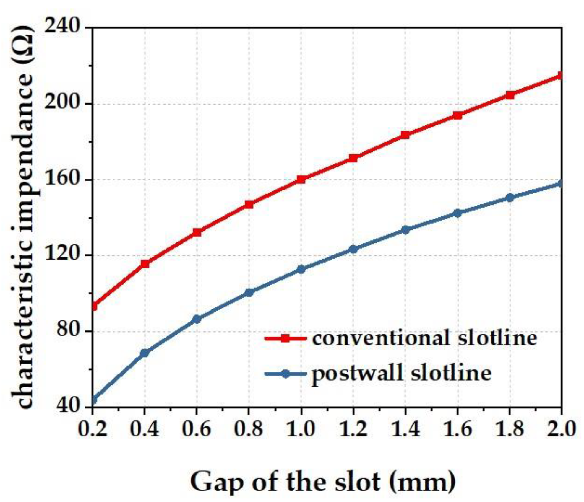
2.2. PWS-SIR Resonator
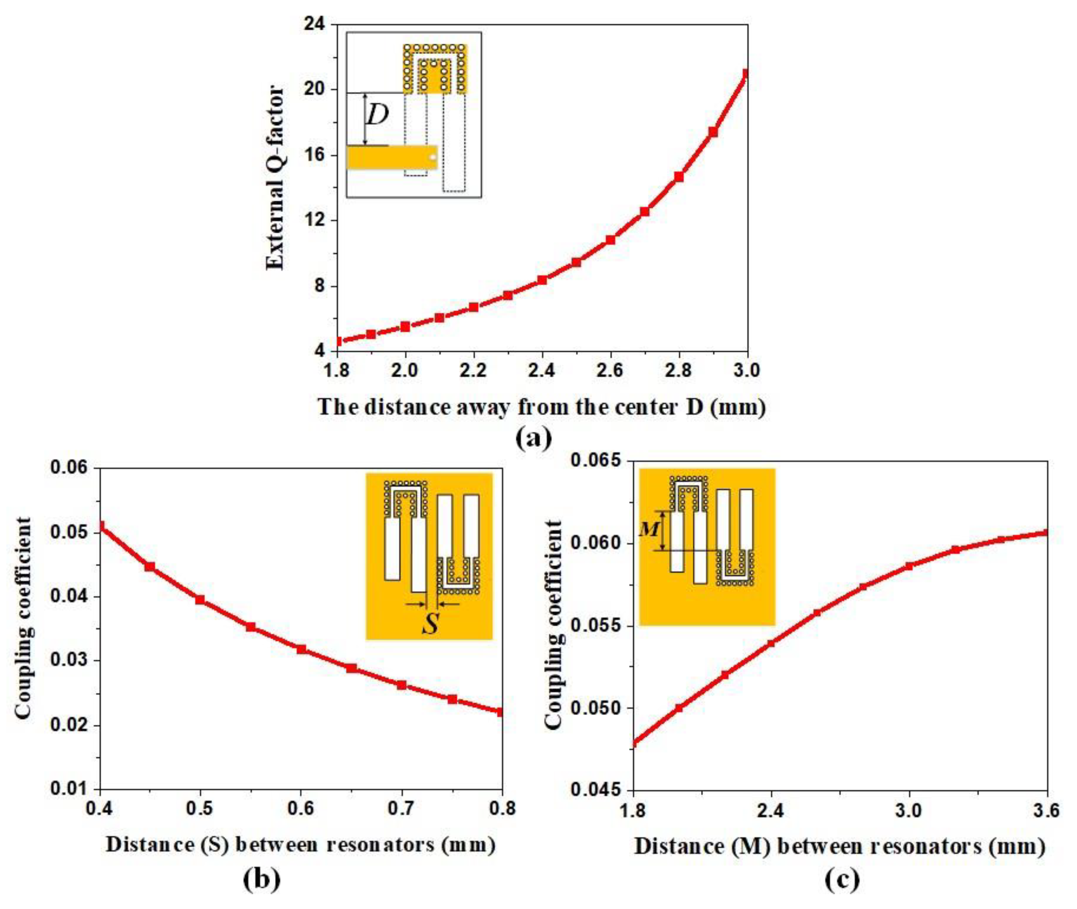
As shown in Figure 1a, the characteristic impendence and electrical length of PWS are defined as Z1 and θ1. Similarly, the characteristic impendence and electrical length of CSL are Z2 and θ2. Besides, the impedance ratio of SIR, defined as K = Z1/Z2, is less than 1.00. According to the theory of the SIR [22], when the SIR is resonating, Kpws and electrical length can be expressed as follows:
K p w s = Z 1 Z 2 = tan θ 1 × tan θ 2 < 1
θ 1 + θ 2 < π 2
The resonator can get a minimum electrical length of less than half of the wavelength when θ1 and θ2 are equivalent, thus achieving the miniaturization of the resonators.
The characteristic impedances of PWS and CSL can be calculated by the full-wave EM simulator ANSOFT HFSS. The characteristic impedance of PWS cannot be achieved like CSL because it is not a uniform transmission line. The characteristic impedance of the PWS can be calculated by the ABCD matrix, which is used to calculate the characteristic impedance of the periodic structure unit [23]. The characteristic impendence of CSL and PWS with different slot width is calculated, as is shown in Figure 2, and the PWS under the same slot width has a smaller impendence than CSL. The PWS adopted for implementing SIR, as shown in Figure 1a, can result in a smaller impendence ratio Kpws and thus a smaller size and a wider upper stopband than CSL-SIR. The characteristic impedance of CSL with a 2 mm gap at the Rogers RO4003C of 0.508 mm thickness is 215 Ω, and the characteristic impedance of the PWS with 0.20 mm gap is 43.88 Ω. The impendence ratio Kpws and the miniaturization ratio of the proposed resonator are 0.20 and 0.62, respectively.
For the filter, the location of the spurious passband is directly related to the filter’s performance, and the spurious passband theory of CSL-SIR is well established [9]. Taking the spurious resonance frequency to be fn (n = 1, 2, 3. etc.) and corresponding electrical length with θn and then the following relation can be achieved:
f 1 f 0 = θ 1 θ 0 = π 2 tan 1 K p w s
where the f0 is the fundamental frequency of the PWS-SIR. Obviously, the spurious passband frequency of the resonator is determined by the impendence ratio Kpws. The spurious passband can be postponed with a smaller impendence ratio of Kpws. Based on the above discussion, the PWS-SIR can achieve a smaller impendence ratio than CSL-SIR, leading to a higher spurious passband. According to Equation (3), the frequency of the first spurious response of the proposed resonator is as follows:
f 1 = θ 1 θ 0 f 0 = π 2 tan 1 K p w s f 0 = 3.66 f 0
The unloaded quality factor (Q-factor) of the resonator has a great influence on the insertion loss of the filter. To compare the unloaded Q-factor of PWS-SIR and CSL-SIR, the loss of these resonators when they resonate at 4.9 GHz with the same feeding structure is simulated, as shown in Table 1. It can be seen that the radiation loss of the PWS-SIR is smaller, which is 55.6 percent of the radiation loss of the CSL-SIR. Due to the half-closed field distribution of the PWS, more electric field is concentrated in the substrate. Thus, the radiation loss and the crosstalk to other devices of the PWS-SIR are smaller. This means the PWS-SIR has a relatively high unloaded Q-factor.

2.3. Filter Design

A third-order filter with a bandwidth BW = 200 MHz centered at f0 = 4.9 GHz is implemented with the proposed PWS-SIRs. Coupling matrix and external Q-factors are obtained from filter design tool provided by the commercial simulation software CST Microwave Studio. The obtained external Q-factor is 13.93, and the coupling matrix m is as follows:
m = [ 0 0.042 0 0.042 0 0.042 0 0.042 0 ]
For the resonator dimensions designed as shown in Figure 1, the proposed resonator resonates at 4.9 GHz. Based on the proposed resonator’s current distribution in Figure 1b, the current of the U-shaped resonator is largest at the slot end, and the currents of the two terminals flow in opposite directions. The cancellation currents greatly reduce the radiation loss of the resonator, and consequently, a high unloaded Q-factor is achieved.
The distance between the microstrip line and the center of the board D affects the external Q-factor, and the relationship curve is shown in Figure 3a. The coupling coefficient of the filter depends on the distance between the resonators in x- and y-direction M and S. The relationship between the distance and the coupling coefficient was obtained by simulation in CST, as presented in Figure 3b,c.
According to the results in Figure 3, S, M, and D can be optimized to satisfy the coupling coefficient and external Q-factor, which has been calculated theoretically. To compensate for the influence of the feeding microstrip on the resonator, the length of the first and the last resonator need to increase Ls (0.85 mm). The CSL filter used for comparison is also designed in the same way.

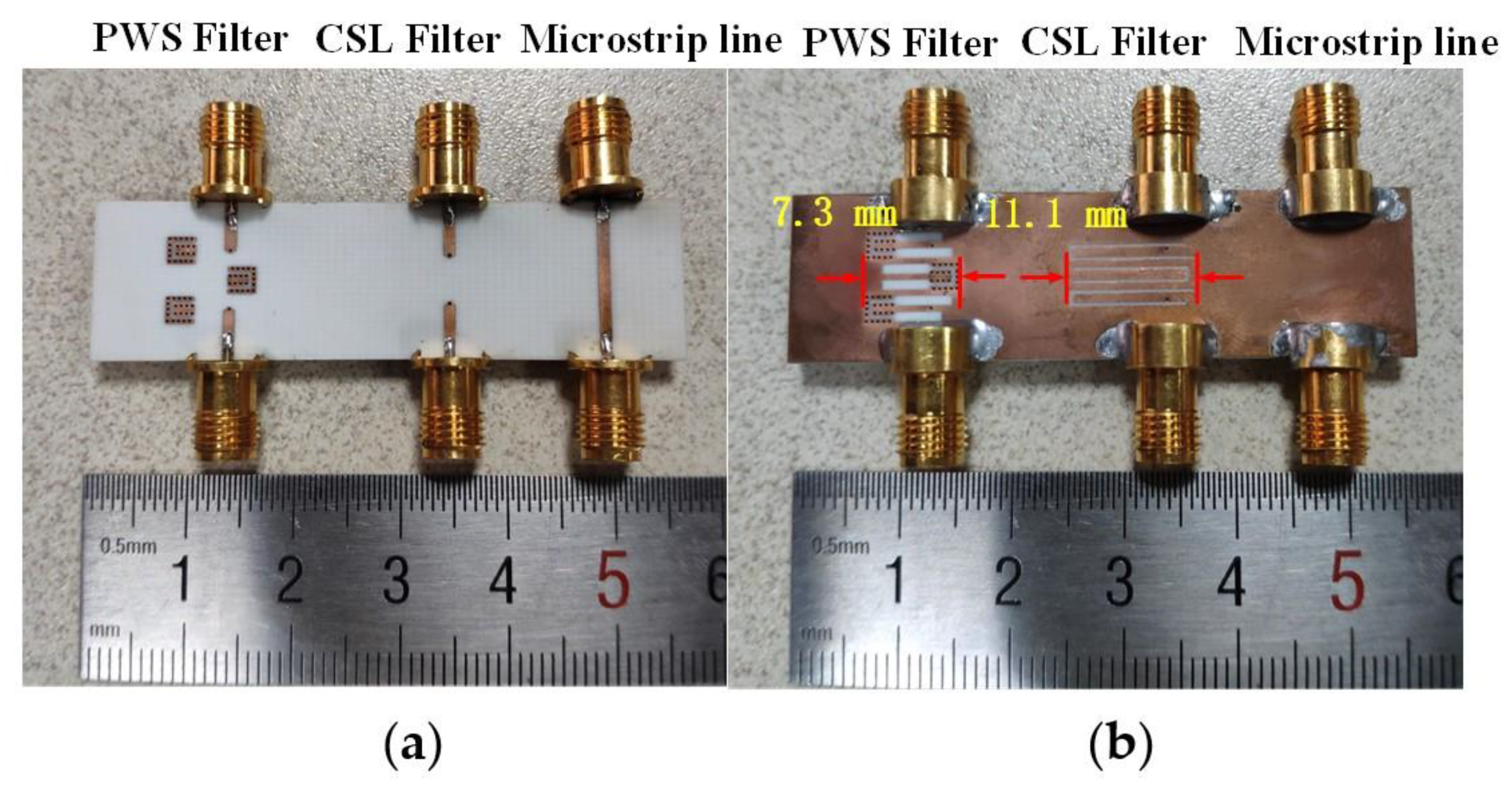
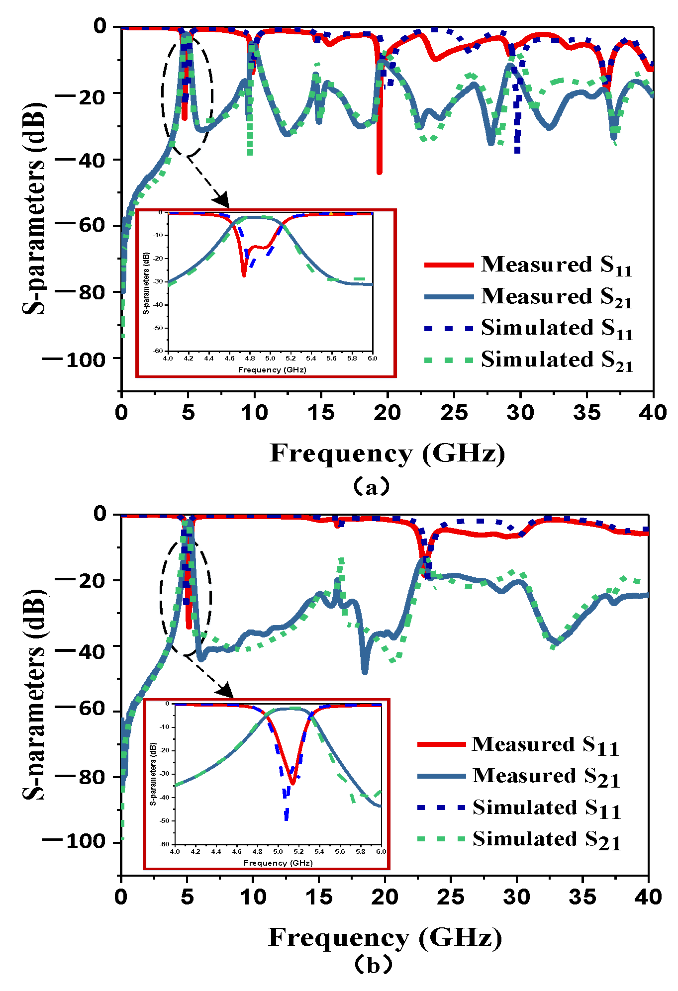
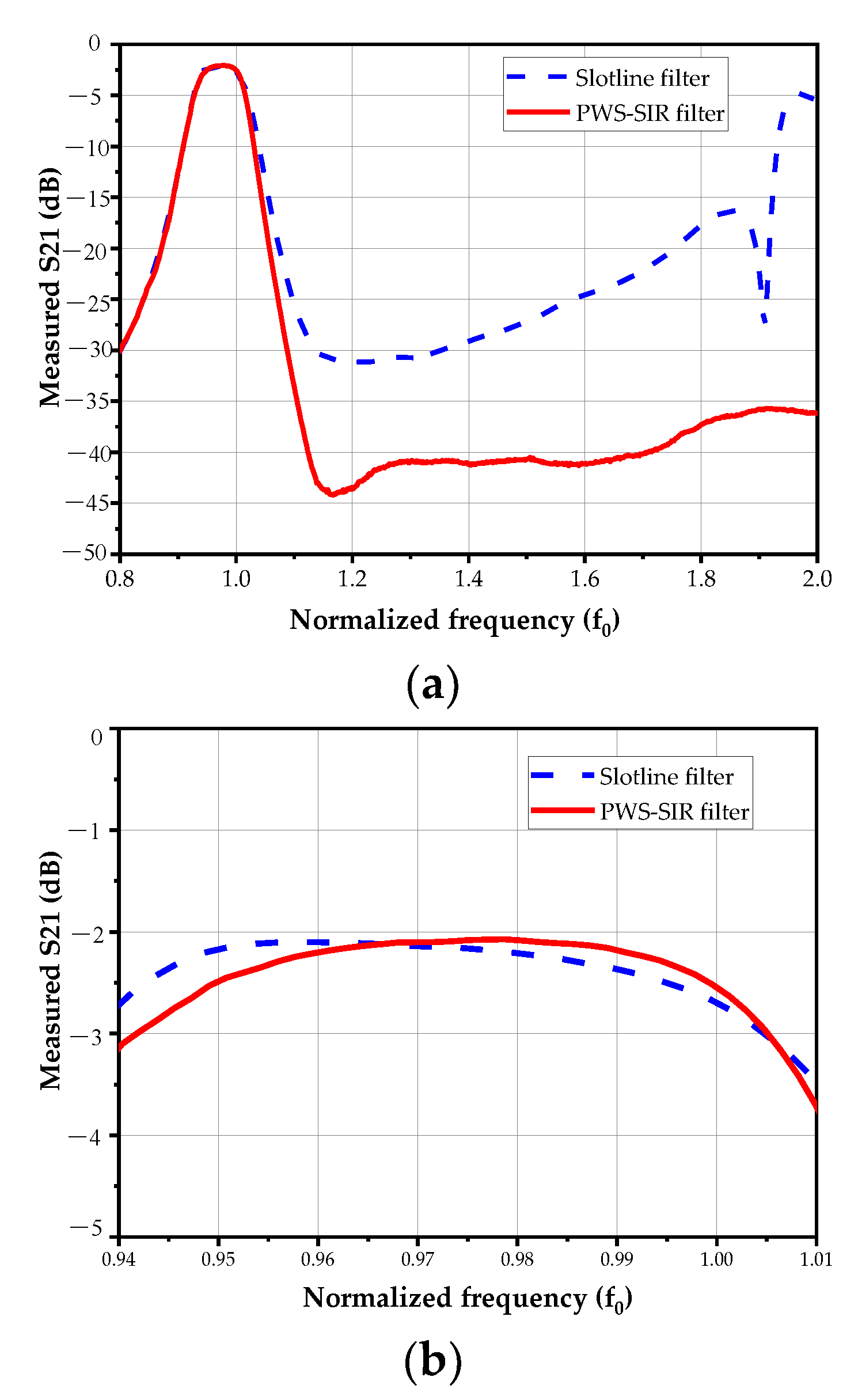
3. Fabrication and Measurement Results

The proposed PWS-SIR and CSL filters have been designed, fabricated, and measured. Dimensions of the fabricated filter are the same as that in Figure 1d: width of microstrip feed line Wmsp is 1.1 mm, the distance between via holes Vd is 0.6 mm, the radius of the via holes Vr is 0.15 mm, the distance between the microstrip line and the center of the board D is 2.7 mm, the distance between the resonators in x-direction M is 2.9 mm, the distance between the resonators in y-direction S is 0.6 mm, the length of the high impedance slot with a shorter length in the resonator on one side L1 is 4.02 mm, the length of the PWS in x-direction L2 is 2 mm, the length of the PWS in y-direction L3 is 1.6 mm, Ls = 0.85 mm, the width of the high impedance slot W1 is 2 mm, and the width of the PWS W2 is 0.2 mm. Figure 4 shows the photo of the two filters. The two filters are fabricated on the same substrate (Rogers RO4003C) with a 0.508 mm thickness, whose dielectric constant is 3.38, and a microstrip line is also made on the board for calculating approximately the insertion loss of the connector and microstrip line. The length of the CSL filter resonator is 11.1 mm (0.34λg), and the length of the proposed filter resonator is just 7.3 mm (0.22λg), which is 35% smaller than the CSL filter.
The two filters are measured by a Keysight N5224A vector network analyzer, and the measured results of both filters are shown in Figure 5. The measured passband insertion loss of the PWS-SIR filter and the CSL filter are both 1.7 dB, which are in good agreement with the simulated ones. In Figure 5b, the stopband rejection of the PWS-SIR filter is better than −20 dB from 5 GHz to 23 GHz, which shows that the PWS-SIR filter has a wide stopband rejection up to 4.7f0. The stopband of the CSL is just up to 10 GHz (2 f0), as shown in Figure 5a. And it can be noted that the suppression of the spurious passband predicted at 3 f0 is better than 25 dB. As a result, compared to a CSL filter, at the same passband bandwidth, the proposed PWS-SIR filter has not only a smaller size but also a wider upper stopband. The insertion loss and the upper stopband rejection comparisons of the conventional slotline filter and the PWS-SIR filter at normalized frequency are shown in Figure 6a,b. The results show that the wideband rejection of the PWS-SIR filter is improved definitely with similar insertion loss. A comparison table with state-of-the-art of slotline filters is shown in Table 2. It shows that the proposed PWS-SIR filter has a wide upper stopband among slotline based filters. The microstrip-based filters and microstrip-slotline combined filters usually outperform slotline based filters because of their structural features.

4. Conclusions

A third-order PWS-SIR BPF has been proposed and investigated in this letter. The advantages of PWS-SIR have been explained with both the simulation and the experiment. It has been shown that the PWS-SIR BPF has a wider upper stopband and a smaller size compared to its counterpart CSL-SIR BPF. In addition, the upper stopband rejection of the PWS-SIR BPF is also better than CSL-SIR BPF. It demonstrates that the PWS-SIR filter would have a wider application than the CSL filter, especially in integrated circuits and miniaturized communication systems requiring better interference suppression in the wide upper stopband.

Author Contributions

Conceptualization, S.L., H.Z. and X.Y.; Methodology, L.Y., C.L. and J.W.; Validation, L.Y.; Formal analysis, L.Y.; Data curation, C.L. and J.W.; Writing-original draft preparation, L.Y.; Writing-review and editing, C.L. and J.W.; Supervision, S.L., H.Z. and X.Y.; Project administration, S.L., H.Z. and X.Y. All authors have read and agreed to the published version of the manuscript.

Funding

This research was funded by the National Natural Science Foundation of China under Grant 61801116 and 61771127.

Institutional Review Board Statement

Not applicable.

Informed Consent Statement

Not applicable.

Data Availability Statement

Not applicable.

Conflicts of Interest

The authors declare no conflict of interest.

References

  1. Mandal, M.K.; Sanyal, S. Compact Wide-Band Bandpass Filter Using Microstrip to Slotline Broadside-Coupling. IEEE Microw. Wirel. Compon. Lett. 2007, 17, 640–642. [Google Scholar] [CrossRef]
  2. Remillard, S.; Radzikowski, P.; Cordone, S.; Applegate, D.; Mehrotra, A.; Kokales, J.; Abdelmonem, A. A closed slot-line resonator filter. IEEE Microw. Wirel. Compon. Lett. 2004, 14, 234–236. [Google Scholar] [CrossRef]
  3. Sun, S.; Menzel, W. Novel dual-mode balun bandpass filters using single cross-slotted patch resonator. IEEE Microw. Wirel. Compon. Lett. 2011, 21, 415–417. [Google Scholar] [CrossRef]
  4. Killamsetty, V.K.; Mukherjee, B. Compact Wideband Bandpass Filter for TETRA Band Applications. IEEE Microw. Wirel. Compon. Lett. 2017, 27, 630–632. [Google Scholar] [CrossRef]
  5. Killamsetty, V.; Mukherjee, B. Miniaturised highly selective wide-band bandpass filter using dual-mode resonators and inter digital capacitors. Electron. Lett. 2017, 53, 1209–1211. [Google Scholar] [CrossRef]
  6. Feng, L.-P.; Zhu, L. Strip-Loaded Slotline Resonator for Compact Differential-Mode Bandpass Filters with Improved Upper Stopband Performance. IEEE Microw. Wirel. Compon. Lett. 2017, 27, 108–110. [Google Scholar] [CrossRef]
  7. Luo, X.; Ma, J.-G. Compact Slot-Line Bandpass Filter Using Backside Microstrip Open-Stubs and Air-Bridge Structure for Spurious Suppression. In Proceedings of the 2009 Asia Pacific Microwave Conference, Singapore, 7–10 December 2009. [Google Scholar]
  8. Azadegan, R.; Sarabandi, K. Miniature High-Q Double-Spiral Slot-Line Resonator Filters. IEEE Trans. Microw. Theory Tech. 2004, 52, 1548–1557. [Google Scholar] [CrossRef]
  9. Lee, J.; Sarabandi, K. A Miniaturized Conductor-Backed Slot-Line Resonator Filter With Two Transmission Zeros. IEEE Microw. Wirel. Compon. Lett. 2006, 16, 660–662. [Google Scholar] [CrossRef] [Green Version]
  10. Lee, C.; Hsu, C.G.; Chen, C. Band-Notched Balanced UWB BPF With Stepped-Impedance Slotline Multi-Mode Resonator. IEEE Microw. Wirel. Compon. Lett. 2012, 22, 182–184. [Google Scholar] [CrossRef]
  11. Guo, X.; Zhu, L.; Wu, W. A Dual-Wideband Differential Filter on Strip-Loaded Slotline Resonators with Enhanced Coupling Scheme. IEEE Microw. Wirel. Compon. Lett. 2016, 26, 882–884. [Google Scholar] [CrossRef]
  12. Kuo, J.-T.; Shih, E. Microstrip stepped impedance resonator bandpass filter with an extended optimal rejection band-width. IEEE Trans. Microw. Theory Tech. 2003, 51, 1554–1559. [Google Scholar]
  13. Lopetegi, T.; Laso, M.A.; Falcone, F.; Martin, F.; Bonache, J.; Garcia, J.; Perez-Cuevas, L.; Sorolla, M.; Guglielmi, M. Mi-crostrip “Wiggly-Line” bandpass filters with multispurious rejection. IEEE Microw. Wirel. Compon. Lett. 2004, 14, 531–533. [Google Scholar] [CrossRef]
  14. Chen, C.-F.; Huang, T.-Y.; Wu, R.-B. Design of microstrip bandpass filters with multiorder spurious-mode suppression. IEEE Trans. Microw. Theory Tech. 2005, 53, 3788–3793. [Google Scholar] [CrossRef]
  15. Lin, S.C.; Kuo, T.N.; Lin, Y.S.; Chen, C.H. Novel coplanar-waveguide bandpass filters using loaded air-bridge enhanced capacitors and broadside-coupled transition structures for wideband spurious suppression. IEEE Trans. Microw. Theory Tech. 2006, 54, 3359–3369. [Google Scholar]
  16. Luo, X.; Ma, J.-G.; Li, E.-P.; Ma, K. Hybrid microstrip T-Stub/defected ground structure cell for electromagnetic interference bandpass filter design. IEEE Trans. Electromagn. Compat. 2011, 53, 717–725. [Google Scholar]
  17. Kim, C.H.; Chang, K. Wide-Stopband Bandpass Filters Using Asymmetric Stepped-Impedance Resonators. IEEE Microw. Wirel. Compon. Lett. 2013, 23, 69–71. [Google Scholar] [CrossRef]
  18. Chu, P.; Hong, W.; Dai, L.; Tang, H.; Hao, Z.-C.; Chen, J.; Wu, K. Wide Stopband Bandpass Filter Implemented With Spur Stepped Impedance Resonator and Substrate Integrated Coaxial Line Technology. IEEE Microw. Wirel. Compon. Lett. 2014, 24, 218–220. [Google Scholar] [CrossRef]
  19. Malherbe, J.A.G. Wideband Bandpass Filter With Extremely Wide Upper Stopband. IEEE Trans. Microw. Theory Tech. 2018, 66, 2822–2827. [Google Scholar] [CrossRef] [Green Version]
  20. Makimoto, M.; Yamashita, S. Bandpass Filters Using Parallel Coupled Stripline Stepped Impedance Resonators. IEEE Trans. Microw. Theory Tech. 1980, 28, 1413–1417. [Google Scholar] [CrossRef]
  21. Li, S.; Yin, X.; Zhao, H.; Qi, H. Post-Wall Slotline and its Application in Design of Short Pulse Tapered Slot Antennas. IEEE Trans. Antennas Propag. 2015, 63, 1. [Google Scholar] [CrossRef]
  22. Sagawa, M.; Makimoto, M.; Yamashita, S. Geometrical structures and fundamental characteristics of microwave stepped-impedance resonators. IEEE Trans. Microw. Theory Tech. 1997, 45, 1078–1085. [Google Scholar] [CrossRef]
  23. Pozar, D.M. Microwave Engineering; John Wiley & Sons: Hoboken, NJ, USA, 2009; pp. 320–322. [Google Scholar]
  24. Sangam, R.S.; Dash, S.; Kshetrimayum, R.S. Ultra-Broadband Bandpass Filter Using Linearly Tapered Coupled-Microstrip Line and Open Loop Defected Ground Structure. IEEE Trans. Circuits Syst. II Express Briefs 2021, 68, 181–185. [Google Scholar] [CrossRef]
Figure 1. The proposed BPF. (a) The SIR composed of PWS, (b) the current distribution at the resonance frequency, (c) the top view, (d) the bottom view.
Electronics 11 00851 g001
Figure 2. Characteristic impedance of the PWS and the conventional slotline.
Electronics 11 00851 g002
Figure 3. External Q-factor and coupling coefficients of the PWS filter.
Electronics 11 00851 g003
Figure 4. The photo of the proposed BPF. (a) the top view of the BPF board, (b) the bottom view of the BPF board.
Electronics 11 00851 g004
Figure 5. Comparison between simulation and measurement of both BPF. (a) CSL filter, (b) PWS filter.
Electronics 11 00851 g005
Figure 6. The insertion loss (a) and the upper stopband rejection (b) comparisons of the conventional slotline filter and the PWS-SIR filter at normalized frequency.
Electronics 11 00851 g006
Table 1. The Loss Percentage of Two Resonators.
Conductor Loss (%)Dielectric Loss (%)Radiation Loss (%)Total Loss (%)
PWS-SIR0.5940.6047.2158.410
CS-SIR0.5530.57212.97514.095
Table 2. Comparison Of The Slotline Filters With State-Of-The-Art.
f0
/GHz
Insertion Loss/dBSize
/λ0
Upper Stopband
(>20 dB)/f0
Structure
[6]30.670.55 × 0.82.30Strip loaded CSL
[7]2.4420.152 × 0.206Lower than 18 dBCSL-MS 1
[9]2.1120.078 × 0.0872.37Conductor-Backed CSL
[10]4.050.830.21 × 0.173.56CSL-SIR
[11]2.640.880.40 × 0.201.74CSL-SIR
[12]1.530.78 × 0.148.3MS-SIR
[13]2.521.04 × 0.396.4Wiggly-Line SIR
[14]1.512.70.32 × 0.228.3MS-SIR
[17]1.52.520.16 × 0.1211.3MS-SIR
[19]0.40.5 8.5Stub loaded MS
[24]8.31.50.31 × 0.552.41Tapered MS
This work4.91.70.22 × 0.224.7PWS-SIR
1 “MS” is abbreviation of microstrip.
Publisher’s Note: MDPI stays neutral with regard to jurisdictional claims in published maps and institutional affiliations.

