Design of an Electromagnetism-Based Transmission Line Galloping Test System
Abstract
:1. Introduction
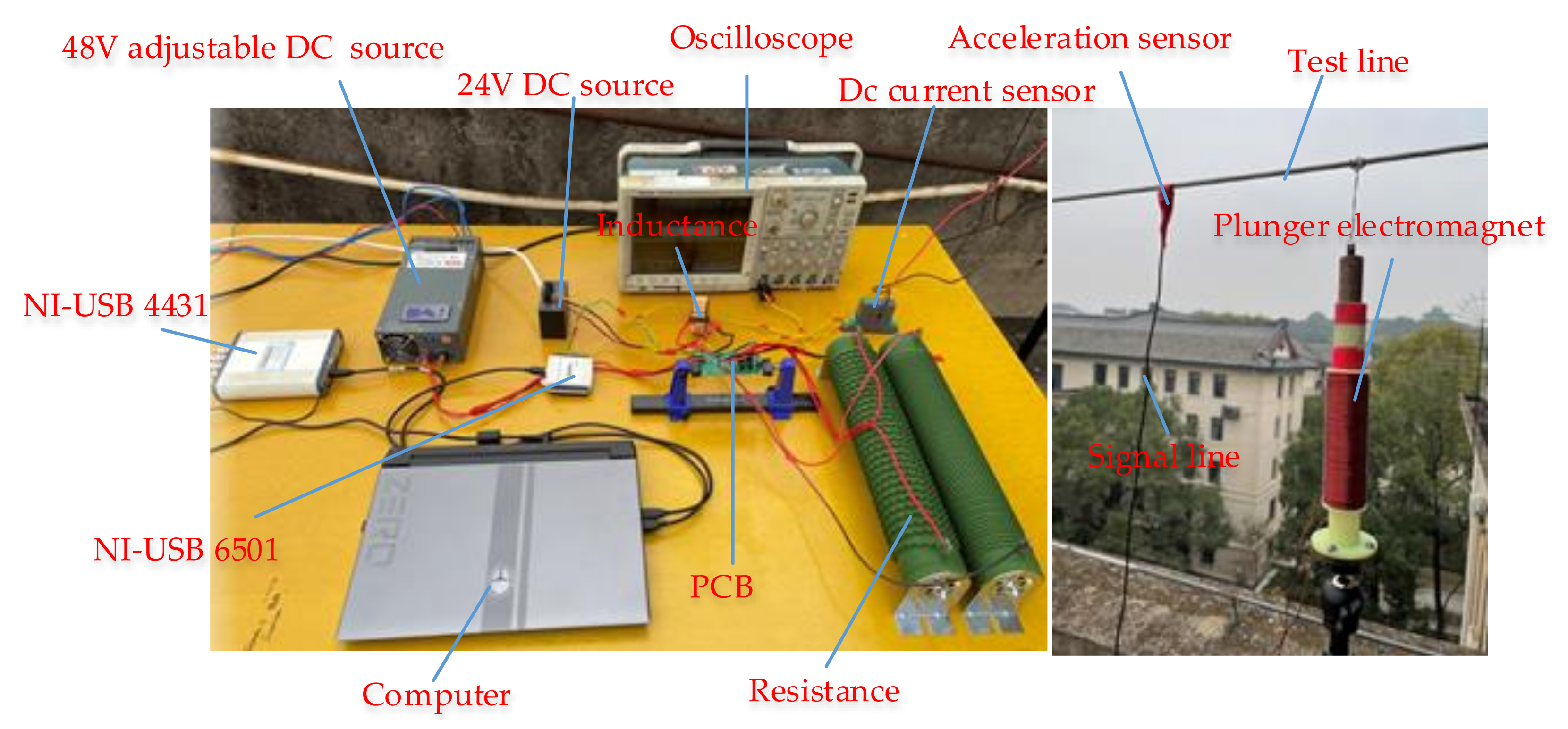
2. Composition of the Electromagnetism-Based Test System
3. System Design Specification
3.1. Reduced-Scale Test Line
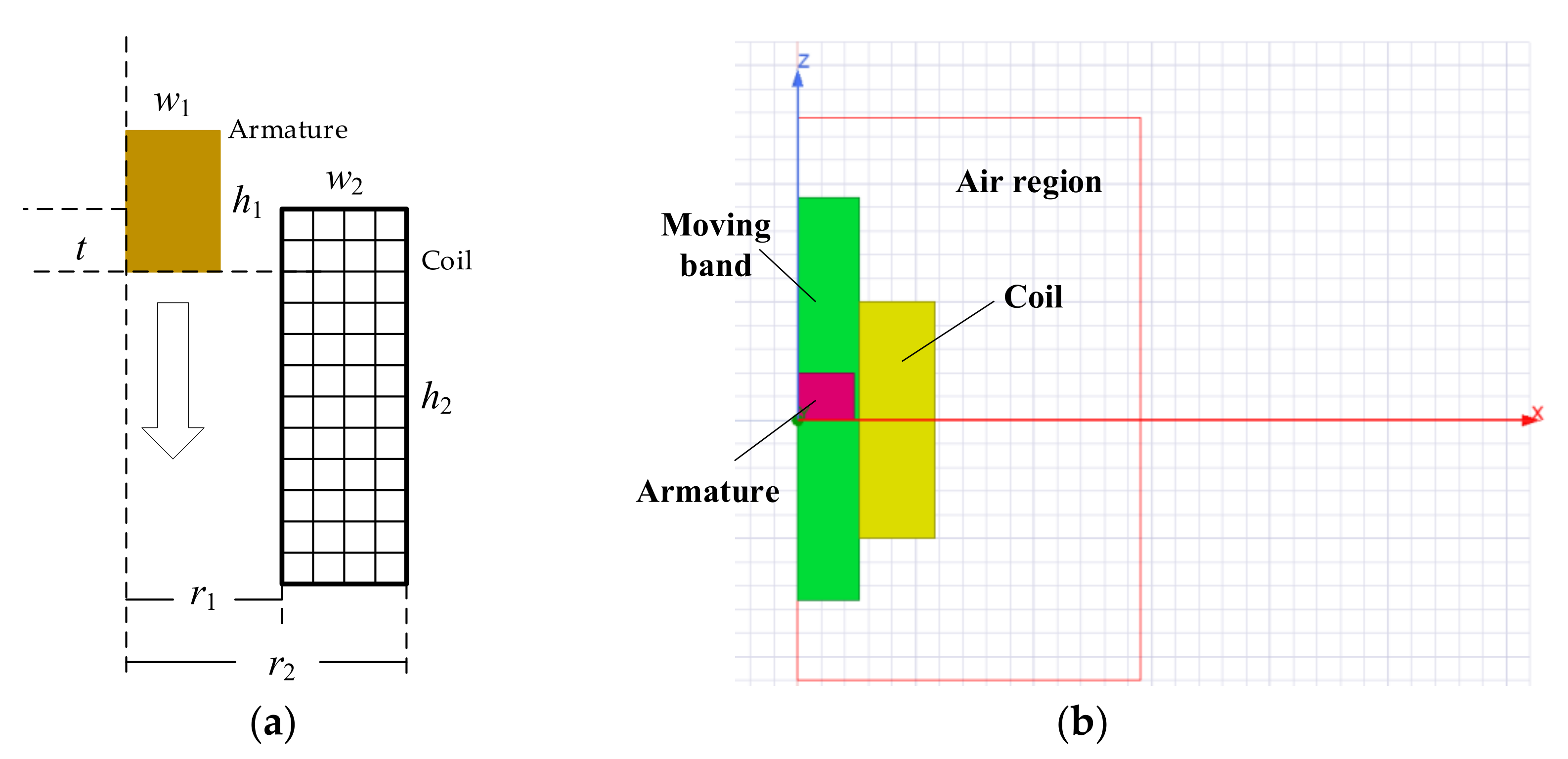
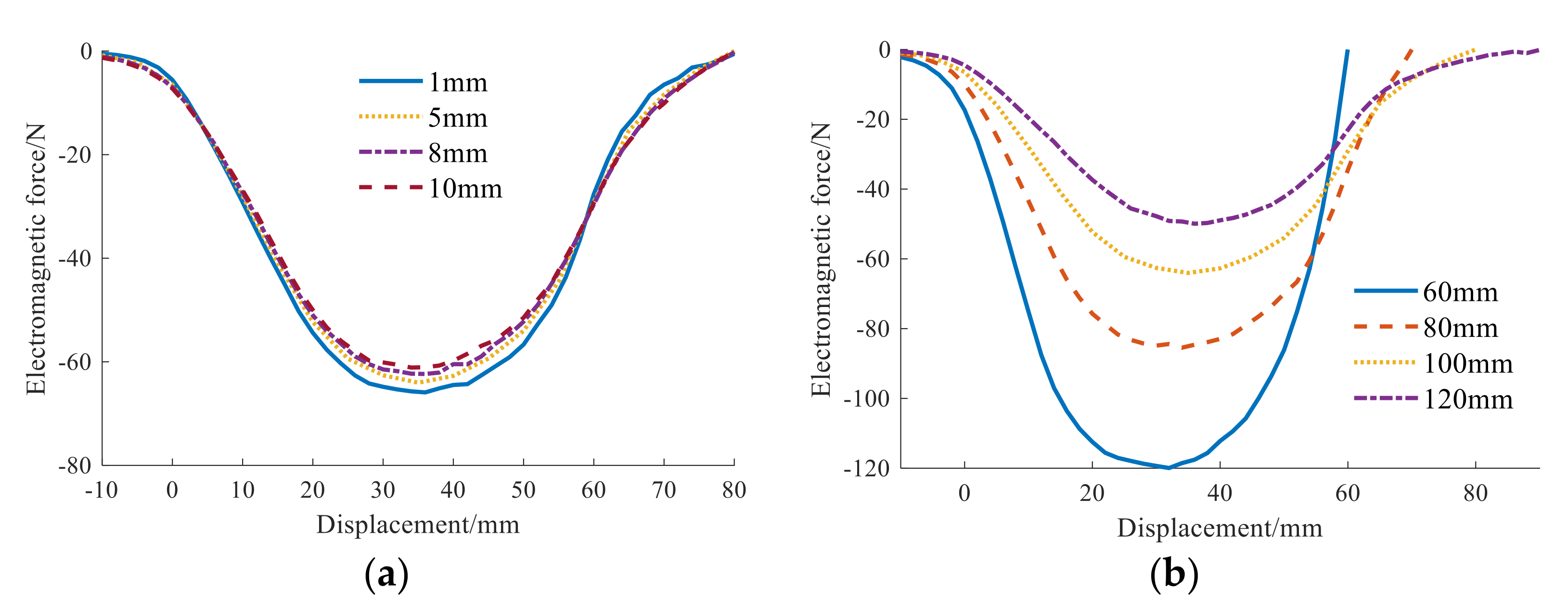
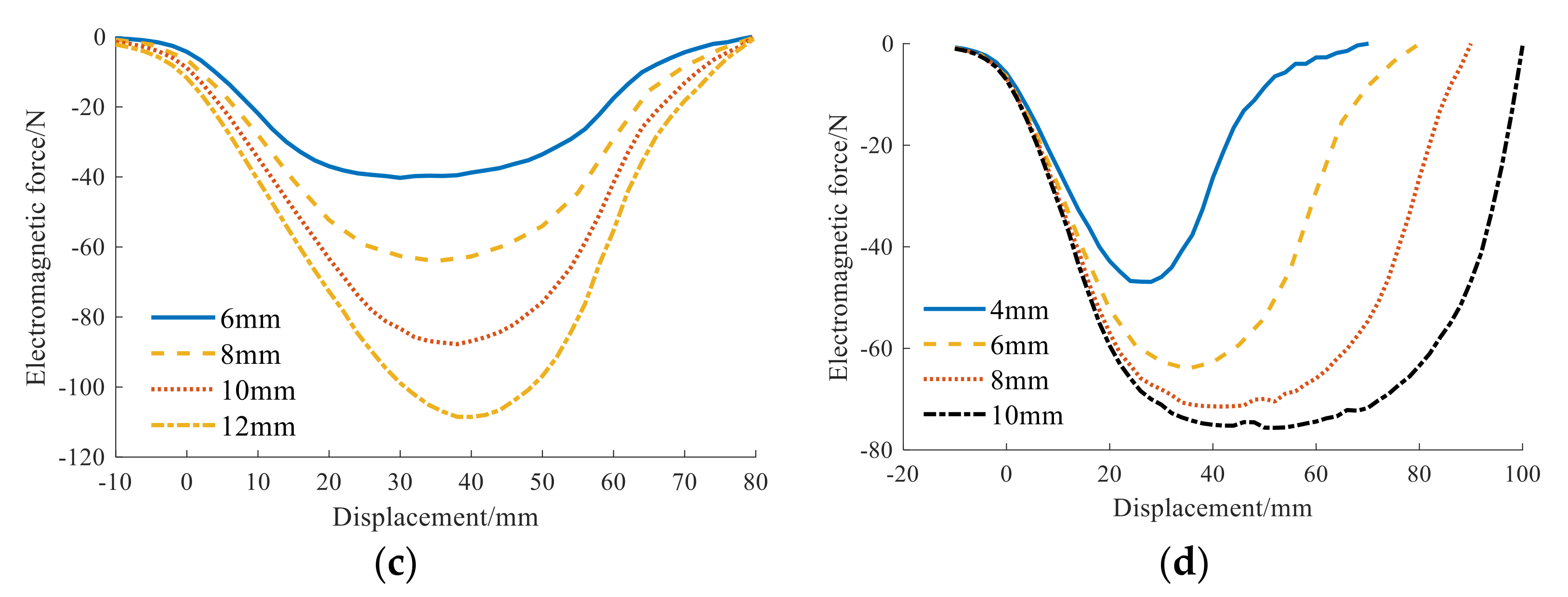
3.2. Plunger Electromagnet
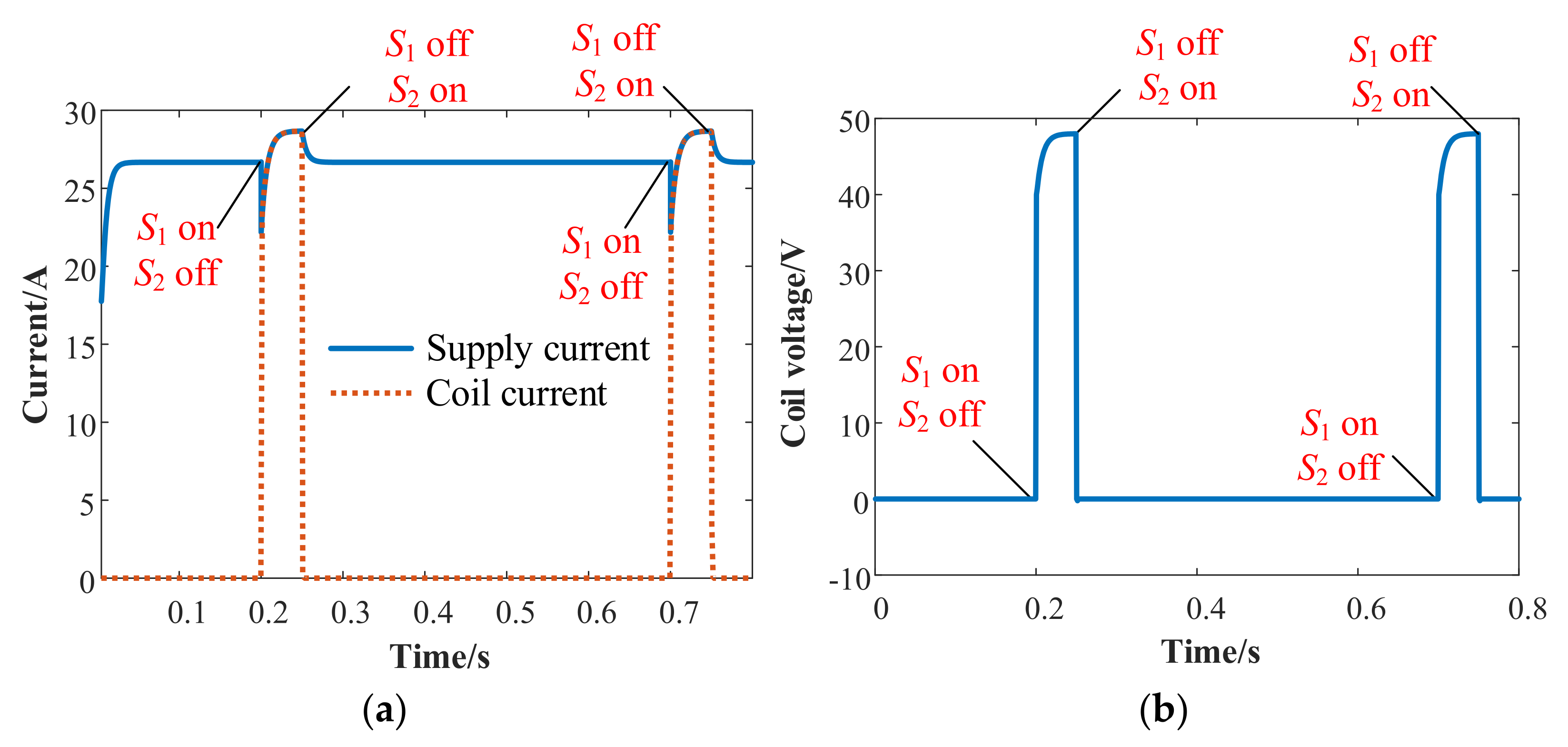
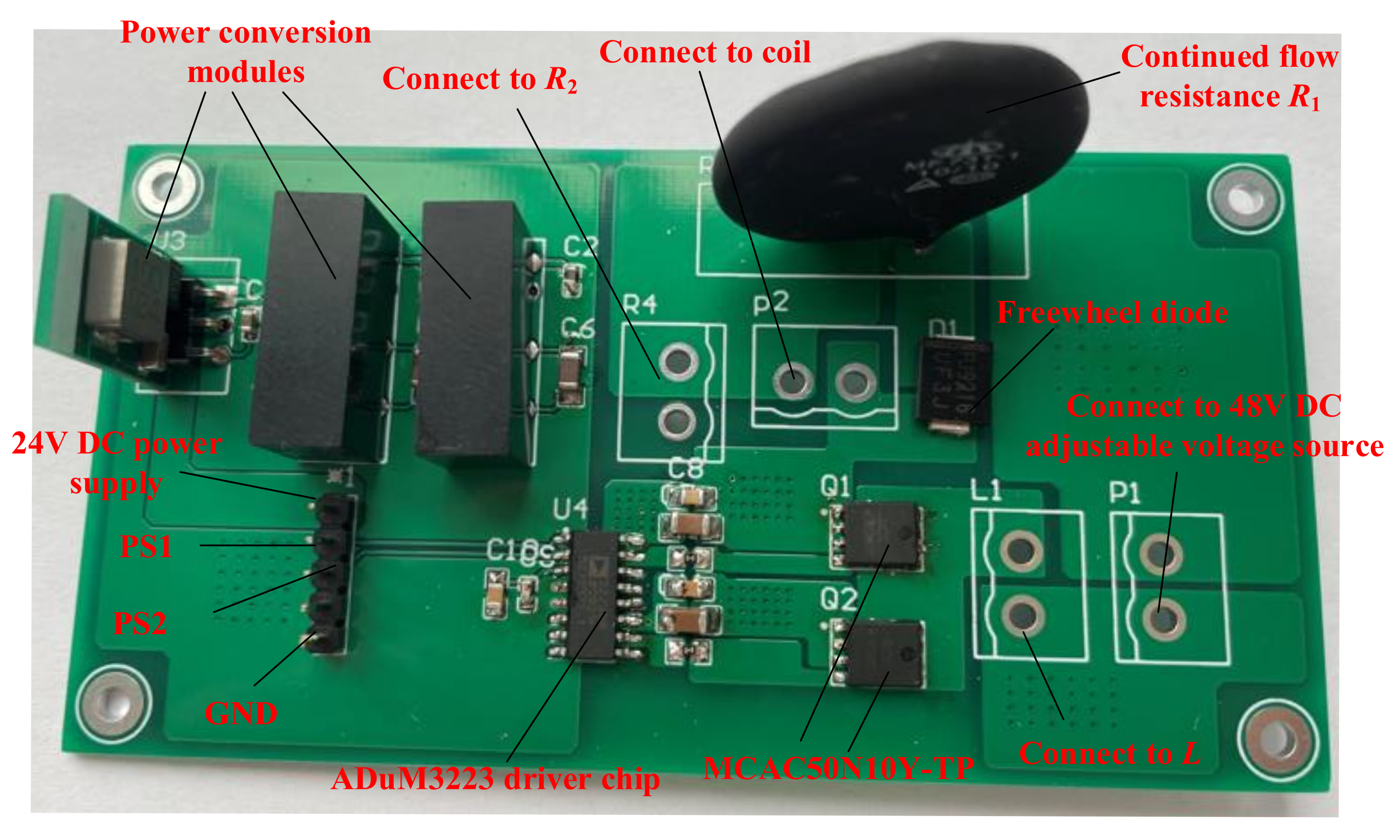
3.3. The Power Supply Circuit
3.4. Switch Control Loop
3.5. Signal Acquisition and Processing
4. Test Results and Discussion
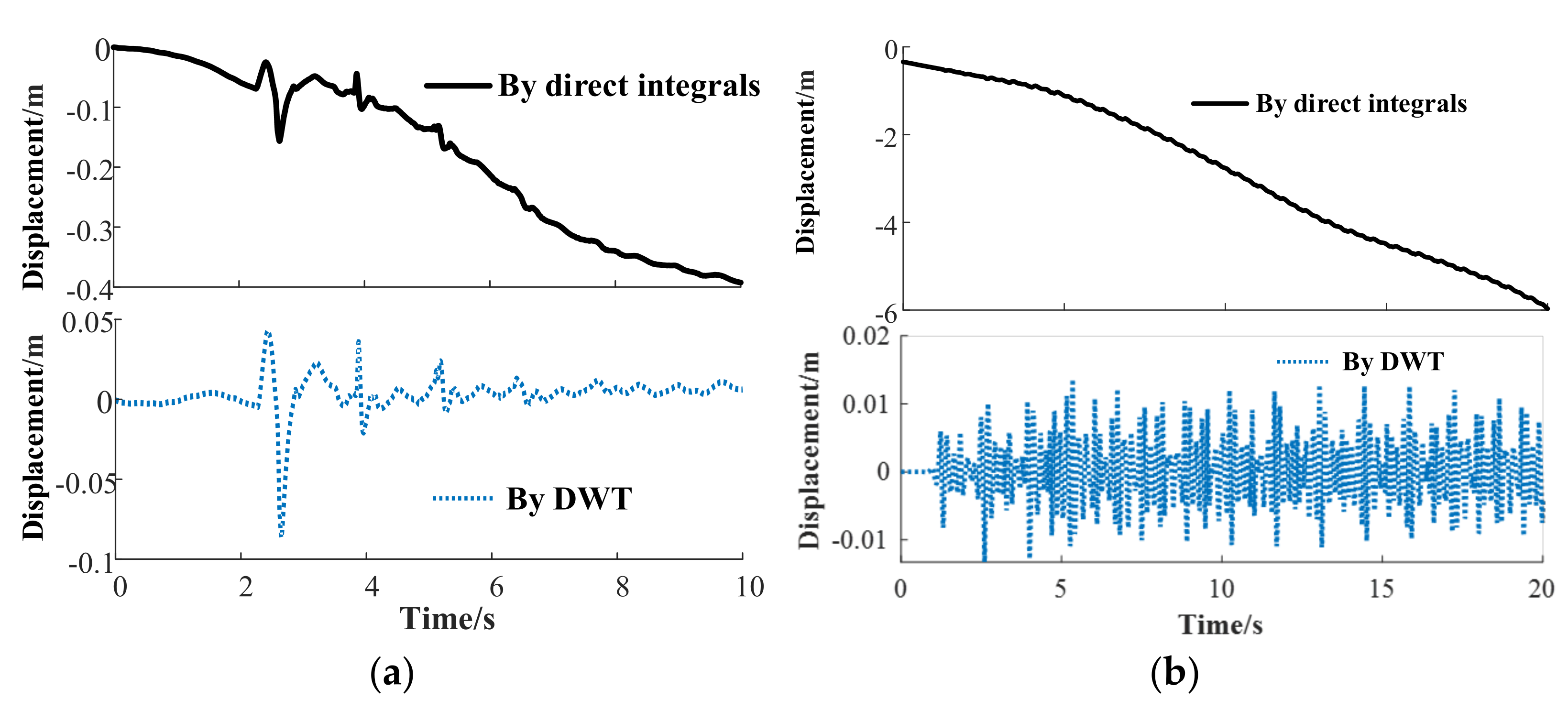
4.1. Calculation of Vibration Displacement
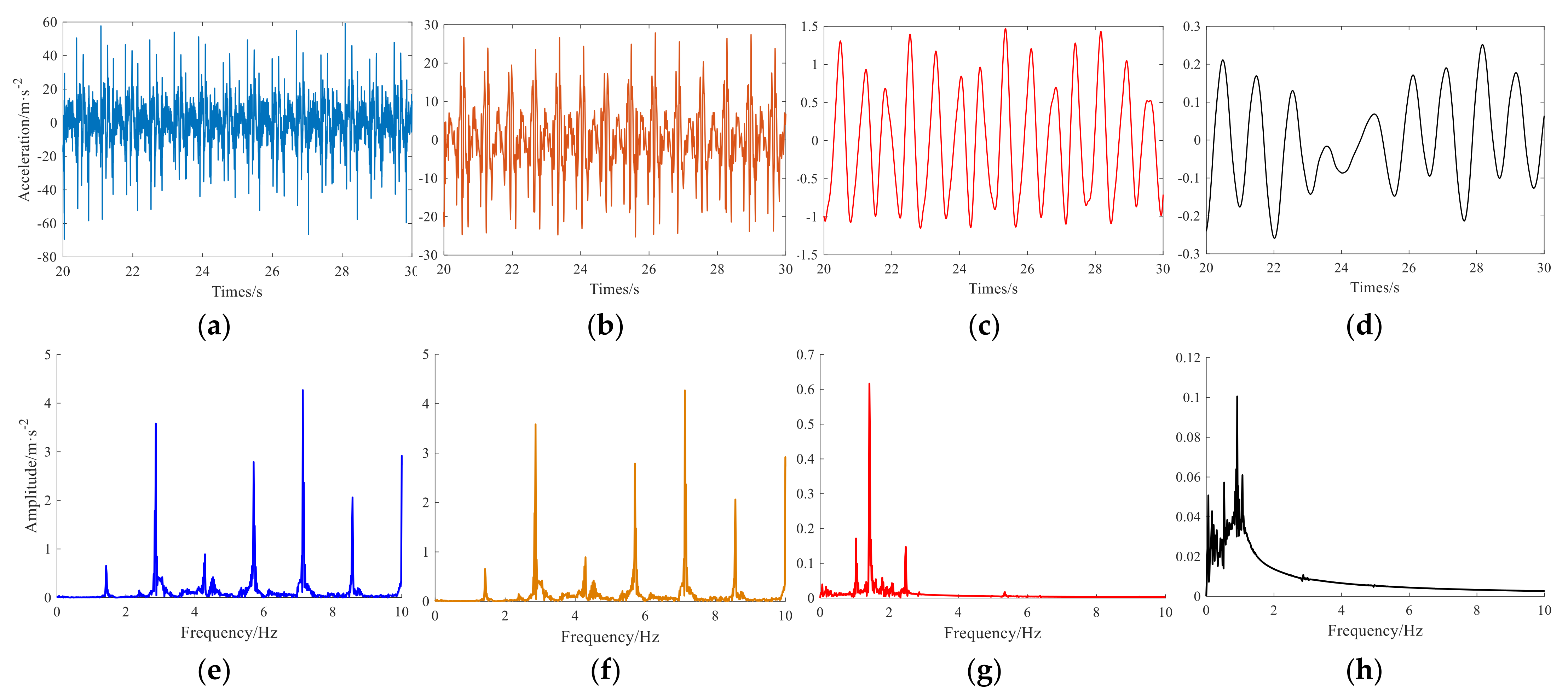
4.2. Judgment of Excitation Interval Time
4.3. Measured Results of Wire Vibration under Adaptive Excitation
5. Conclusions
- (1)
- Taking a reduced-scale test line with a 35.4 m span as an example, the plunger electromagnet and the corresponding power supply loop were designed to provide the impulse excitation force for the wire system. Acceleration sensors, DSA device, digital I/O device and computer were used to monitor wire vibration and control the coil current.
- (2)
- The vibration displacement curve obtained by direct integration is seriously distorted. The calculation method based on DWT was proposed in this paper. The displacement–time curve obtained after DWT treatment fluctuates around 0, which is consistent with the observation result.
- (3)
- Considering the geometric nonlinearity, the adaptive excitation method based on wavelet analysis of the original measured acceleration data was proposed. It can extract the feature of acceleration and reduce the time of judging the excitation interval. The test results show that the wire displacement under fixed interval excitation contains high-order components, and the vibration amplitude fluctuates greatly. Under adaptive electromagnetic force excitation, the vibration frequency of the wire is close to the second-order inherent frequency, and the vibration amplitude increases at first and then remains constant within a certain range due to damping. The vibration pattern is consistent with the two-loop mode of actual transmission line galloping.
- (4)
- When the supply voltage is set as 20, 25 and 30 V, the vibration amplitude of the wire in the stable stage is about 4–6 cm, 6–9 cm and 10–15 cm, respectively. This shows that the vibration amplitude can be controlled by coil current.
Author Contributions
Funding
Data Availability Statement
Conflicts of Interest
References
- Tian, L.; Guo, L.; Ma, R.; Gai, X.; Wang, W. Full-Scale Tests and Numerical Simulations of Failure Mechanism of Power Transmission Towers. Int. J. Struct. Stab. Dyn. 2018, 18, 1850109. [Google Scholar] [CrossRef]
- Zhao, L.; Huang, X.; Zhang, Y.; Tian, Y.; Zhao, Y. A Vibration-Based Structural Health Monitoring System for Transmission Line Towers. Electronics 2019, 8, 515. [Google Scholar] [CrossRef] [Green Version]
- Tadeusiewicz, M.; Hałgas, S. A Method for Diagnosing Soft Short and Open Faults in Distributed Parameter Multiconductor Transmission Lines. Electronics 2021, 10, 35. [Google Scholar] [CrossRef]
- Yang, J.; Liu, B.; Zhao, B.; Liu, Y. Method for the Development of Galloping Distribution Maps for Overhead Transmission Lines. IEEE Trans. Power Syst. 2021, 36, 5956–5958. [Google Scholar] [CrossRef]
- Mou, Z.; Yan, B.; Yang, H.; Wu, K.; Wu, C.; Yang, X. Study on anti-galloping efficiency of rotary clamp spacers for eight bundle conductor line. Cold Reg. Sci. Technol. 2022, 193, 103414. [Google Scholar] [CrossRef]
- Den Hartog, J.P. Transmission line vibration due to sleet. Trans. Am. Inst. Electr. Eng. 1932, 51, 1074–1076. [Google Scholar] [CrossRef]
- Nigol, O.; Buchan, P. Conductor galloping-Part II Torsional mechanism. IEEE Trans. Power App. Syst. 1981, PAS-100, 708–720. [Google Scholar] [CrossRef]
- Lou, W.; Wu, D.; Xu, H.; Yu, J. Galloping Stability Criterion for 3-DOF Coupled Motion of an Ice-Accreted Conductor. J. Struct. Eng. 2020, 146, 04020071. [Google Scholar] [CrossRef]
- Li, X.; Nie, X.; Zhu, Y.; You, Y.; Yan, Z. Wind Tunnel Tests on Aerodynamic Characteristics of Ice-Coated 4-Bundled Conductors. Math. Probl. Eng. 2017, 2017, 1628173. [Google Scholar]
- Lu, J.; Wang, Q.; Wang, L.; Mei, H.; Yang, L.; Xu, X.; Li, L. Study on wind tunnel test and galloping of iced quad bundle conductor. Cold Reg. Sci. Technol. 2019, 160, 273–287. [Google Scholar] [CrossRef]
- Matsumiya, H.; Nishihara, T.; Yagi, T. Aerodynamic modeling for large-amplitude galloping of four-bundled conductors. J. Fluids Struct. 2018, 82, 559–576. [Google Scholar] [CrossRef]
- Zhou, L.; Yan, B.; Zhang, L.; Zhou, S. Study on galloping behavior of iced eight bundle conductor transmission lines. J. Sound Vib. 2016, 362, 85–110. [Google Scholar] [CrossRef]
- Zhou, A.; Liu, X.; Zhang, S.; Cui, F.; Liu, P. Wind tunnel test of the influence of an interphase spacer on the galloping control of iced eight-bundled conductors. Cold Reg. Sci. Technol. 2018, 155, 354–366. [Google Scholar] [CrossRef]
- Ruan, J.; Zhang, L.; Cai, W.; Huang, D.; Li, J.; Feng, Z. Study on Adaptive Excitation System of Transmission Line Galloping Based on Electromagnetic Repulsive Mechanism. Shock Vib. 2021, 2021, 2428667. [Google Scholar] [CrossRef]
- Cai, M.; Yan, B.; Lu, X.; Zhou, L. Numerical simulation of aerodynamic coefficients of iced-quad bundle conductors. IEEE Trans. Power Deliv. 2015, 30, 1669–1676. [Google Scholar] [CrossRef]
- Gurung, C.-B.; Yamaguchi, H.; Yukino, T. Identification and characterization of galloping of Tsuruga test line based on multi-channel modal analysis of field data. J. Wind Eng. Ind. Aerodyn. 2003, 91, 903–924. [Google Scholar] [CrossRef]
- Cai, M.; Yang, X.; Huang, H.; Zhou, L. Investigation on Galloping of D-Shape Iced 6-Bundle Conductors in Transmission Tower Line. KSCE J. Civ. Eng. 2020, 24, 1799–1809. [Google Scholar] [CrossRef]
- Zhao, G.; Lu, Z.; Wang, X.; Peng, Y.; Chang, S. Full Scale Experiment for Vibration Analysis of Ice-Coated Bundled-Conductor Transmission Lines. KSCE J. Civ. Eng. 2022, 26, 336–352. [Google Scholar] [CrossRef]
- Hu, J.; Yan, B.; Zhou, S.; Zhang, H. Numerical investigation on galloping of iced quad bundle conductors. IEEE Trans. Power Deliv. 2012, 27, 784–792. [Google Scholar] [CrossRef]
- Seo, Y.; Kim, S.; Kisi, O.; Singh, V.P. Daily water level forecasting using wavelet decomposition and artificial intelligence techniques. J. Hydrol. 2015, 520, 224–243. [Google Scholar] [CrossRef]
- Alickovic, E.; Kevric, J.; Subasi, A. Performance evaluation of empirical mode decomposition, discrete wavelet transform, and wavelet packed decomposition for automated epileptic seizure detection and prediction. Biomed. Signal Process. Control 2018, 39, 94–102. [Google Scholar] [CrossRef]





| Item | Wind Tunnel Test | Full-Scale Test | Proposed Test System |
|---|---|---|---|
| Test object size | Reduced small-scale model | Full-size model | Reduced small-scale or full-size model |
| Necessary environmental conditions | Artificial wind | Natural wind | None |
| Whether the galloping state can be sustained | Yes | No | Yes |
| Whether the amplitude is controllable | Yes | No | Yes |
| Parameters | Value | Similarity Coefficient |
|---|---|---|
| Span length | 35.4 m | 1:8.4 |
| Diameter | 6 mm | 1:9.92 |
| Mass per unit length | 0.1353 kg/m | 1:65.36 |
| Elasticity modulus | 110,000 N/mm2 | 1:0.59 |
| Loop Number | Mode | Natural Frequency (FEM Calculation) | Natural Frequency (Measured Results) |
|---|---|---|---|
| 1 |  | 0.7732 Hz | 0.78 Hz |
| 2 |  | 1.5448 Hz | 1.57 Hz |
| 3 |  | 2.6583 Hz | 2.75 Hz |
| 4 |  | 3.0909 Hz | 3.12 Hz |
| Parameters | Value | Parameters | Value |
|---|---|---|---|
| Coil material | Copper | Armature material | Electrical pure iron |
| Coil external radius | 15 mm | Relative permeability | 4000 |
| Coil inside radius | 10 mm | Radial thickness of armature | 8 mm |
| Axial thickness of coil | 100 mm | Axial thickness of armature | 60 mm |
| Parameters | Value | Parameters | Value |
|---|---|---|---|
| Coil material | Copper | Armature material | Electrical pure iron |
| Coil external radius | 16.2 mm | relative permeability | 4000 |
| Coil inside radius | 12 mm | Radial thickness of armature | 10 mm |
| Axial thickness of coil | 100.8 mm | Axial thickness of armature | 100 mm |
| Diameter of winding conductor part | 0.8 mm | Number of coil radial turns | 5 |
| Thickness of winding insulation | 0.04 mm | Number of coil axial turns | 120 |
Publisher’s Note: MDPI stays neutral with regard to jurisdictional claims in published maps and institutional affiliations. |
© 2022 by the authors. Licensee MDPI, Basel, Switzerland. This article is an open access article distributed under the terms and conditions of the Creative Commons Attribution (CC BY) license (https://creativecommons.org/licenses/by/4.0/).
Share and Cite
Zhang, L.; Ruan, J.; Cai, W.; Li, J.; Huang, D.; Feng, Z. Design of an Electromagnetism-Based Transmission Line Galloping Test System. Electronics 2022, 11, 771. https://doi.org/10.3390/electronics11050771
Zhang L, Ruan J, Cai W, Li J, Huang D, Feng Z. Design of an Electromagnetism-Based Transmission Line Galloping Test System. Electronics. 2022; 11(5):771. https://doi.org/10.3390/electronics11050771
Chicago/Turabian StyleZhang, Li, Jiangjun Ruan, Wei Cai, Jian Li, Daochun Huang, and Zhihui Feng. 2022. "Design of an Electromagnetism-Based Transmission Line Galloping Test System" Electronics 11, no. 5: 771. https://doi.org/10.3390/electronics11050771
APA StyleZhang, L., Ruan, J., Cai, W., Li, J., Huang, D., & Feng, Z. (2022). Design of an Electromagnetism-Based Transmission Line Galloping Test System. Electronics, 11(5), 771. https://doi.org/10.3390/electronics11050771


