Article

High-Voltage Drivers Based on Forming Lines with Extended Quasi-Rectangular Pulses for High-Power Microwave Oscillators

by
Vladislav V. Rostov
*,
Alexei S. Stepchenko
,
Pavel V. Vykhodtsev
and
Ruslan V. Tsygankov
Institute of High Current Electronics, Siberian Branch of Russian Academy of Science, Tomsk 634055, Russia
*
Author to whom correspondence should be addressed.
Electronics 2022, 11(3), 406; https://doi.org/10.3390/electronics11030406
Submission received: 14 December 2021 / Revised: 18 January 2022 / Accepted: 24 January 2022 / Published: 28 January 2022

Abstract

:
The paper considers such modifications of an ordinary pulse-forming line (PFL) as double-width and triple-width forming lines (DWFL, TWFL) built around the PFL by nesting one and two additional uncharged lines, respectively, into its free volume inside the inner conductor of the PFL. The theoretical analysis is supported by simulation and experimental data, showing that the TWFL provides a 3-fold increase in the voltage pulse width and that it can be further increased by an arbitrary integer factor k. The results of the numerical simulations also show the electric field behavior and other features, including the edge effect in the TWFL. The proposed method opens up new opportunities for designing compact high-power microwace (HPM) sources.

1. Introduction

High-voltage drivers based on distributed pulse-forming lines (PFLs) [1] are an excellent power supply for high-power microwave (HPM) oscillators. This type of driver can provide relatively short rise times (of a few nanoseconds) and rectangular voltage pulses that are, in all respects, more beneficial than those formed by Marx generators or modular pulse-forming networks (PFNs) [2]. The only worthy exception is an innovative “zigzag” PFN Marx design that provides a pulse rise time of 5 ns at an output voltage of 400 kV in a beam diode of 100 Ω (burst mode operation for 10 s at 100 Hz) [3].
Shortening the voltage rise is exceptionally important for stable cathode operation during explosive electron emission [4,5,6,7]. It is likely that this weakens the space charge effect at emission centers [8]. If the rise time is also sharpened to ≈10−9 s or less [4,9], one can attain a picosecond EEE accuracy [10] and phase synchronization of parallel microwave channels [11,12]. In addition, shortening the voltage rise decreases the microwave oscillator transit time [11] and increases the efficiency of the beam-to-wave energy conversion [13,14]. Finally, constant beam parameters within the pulse plateau are needed for mode selection, especially in oversized slow wave structures, where one mode should dominate over competitors for as long as possible [15,16]. The advantages of drivers with distributed PFLs were proved, even by the first experiments on millimeter-wavelength relativistic oscillators [17,18] and, later, on Ka, X, and S-band repetitively pulsed backward wave oscillators [5,12,13,14,19,20,21,22].
For the practical application of gigawatt and sub-gigawatt, repetitively pulsed electromagnetic sources with pulses longer than 10–20 ns, a decrease in their dimensions is needed. This is one of the problems that we consider in this paper. The basic features of pulse-forming lines and innovative ways of dimension reduction are analyzed. Our attention was focused on pulse extension, for which we further developed the fruitful idea of pulse width doubling [23] by using an additional, uncharged inner line. This approach has shown obvious advantages in experiments with a double-width PFL [14]. To prove the concept, the laboratory model of a triple-width PFL was created and tested.

2. Basic Properties of a Single FL

The outer dimensions of a single PFL, as a coaxial segment (Figure 1), are determined by its length LFL and the diameter of its outer conductor 2r2.
The wave impedance of the PFL and the electric strength at its inner conductor (at diameter 2r1) can be written as:
ρ = 60 Λ/ε1/2 Ω, where Λ = ln(r2/r1); and
E = U0/(r1 Λ)
where ε is the relative dielectric permittivity of liquid insulation and U0 is the PFL charging voltage before high-voltage switch operation. The high-voltage switch (not shown in Figure 1 to the right) is normally a spark-gap switch operated with N2 at a pressure of ≈1 MPa. Neglecting the edge effects, the PFL stored energy W and the wave propagation time T are expressed as:
W = TU02/2ρ with T = LFL ε1/2/c
where c is a light speed in free space. As it is well known, after the discharge process, the formed at the load voltage pulse width is τp = 2T. With the field strength and PFL outer dimension kept constant, varying r1 (or Λ) gives the condition of maximum stored energy Λ* = 0.5 and ρ* = 30/ε1/2. Thus, for insulation with ordinary transformer oil (ε = 2.25), we have ρ* = 20 Ω [1].
Typically, PFLs are charged with a built-in Tesla transformer, which was originally proposed by [24] and applied to repetitively-pulsed, high-current SINUS accelerators [1,25,26]. In the SINUS accelerators, the transformer comprises cylindrical magnetic cores, a primary winding with one turn, and a secondary winding of approximately 1500 turns. The magnetic coupling ratio between the primary and secondary windings is close to unity if the length of the magnetic cores is many times larger than the radial gap width and the length of the coils is no greater than half the core length. Another feature of the SINUS accelerators (including version SINUS-4 [24]) is the use of thyristors in the primary transformer circuit for energy switching from capacitors charged to ≈500 V, which allows one to power an accelerator from commercial supply lines without additional step-up transformers. The use of such semiconductor switches in the primary transformer circuit determines the charging time tch for PFLs as a coaxial capacitor: from a few microseconds at a voltage pulse width of 4 ns in compact accelerators (SINUS-120, r2 = 6 cm, LFL = 40 cm [20]) to several tens of microseconds in large setups (SINUS-7, r2 = 50 cm, LFL = 500 cm) [1]. With a spiral line instead of L0 (Figure 1), the voltage pulse can be lengthened up to 130 ns [1,13].
Before proceeding to more complex equivalent circuits, let us consider the discharge circuit of a single PFL with an electrical length T and load resistance RL (Figure 2).
Upon operation of its switch (S), a current I = U0/(RL + ρ) arises in the circuit and a voltage pulse UL = U0RL/(RL + ρ) at the load. In the same time, a voltage wave of amplitude Ub = U0ρ/(RL + ρ) propagates in the line. At t = T, the wave front reaches the open end of the line and goes back with the same sign. At t = 2T, the formation of the first (main) pulse is completed. When RL = ρ, there is no reflection from the load, and the energy stored in the PFL is fully transmitted to the load as a main pulse of duration 2T and amplitude equal to half the charge voltage U0.
It should be noted that the voltage pulse width at the load τp = 2T is about three orders of magnitude shorter than the PFL charging time tch. Thus, for pulses of 10 ns and shorter, the PFL length is LFL ≤ 100 cm [26,27,28,29], and for pulses of 100 ns, it should be 10 times longer. The problem of decreasing the PFL length can be solved by using high-permittivity liquids (treated water, alcohol, glycerol, etc.), but this method involves two problems. First, it greatly increases the conductivity [30,31], and this necessitates the use of extremely short PFL charging, hence the abandonment of thyristors in the primary circuit [1]. Second, at UL ≤ 400 kV, the optimum diode impedance of Cherenkov-type relativistic HPM oscillators is RL ≈ 100 Ω or higher, and cannot be decreased without a loss in their efficiency [13,32,33]. At arbitrary PFL and load impedances, there is an energy loss: a series of reflected pulses in addition to the main one at the load. The efficiency of energy transfer from the PFL to the first pulse is given by:
η = (4 RLρ)/(RL + ρ)2
As can be seen, the efficiency drops when the permittivity is high and ρ << RL. This does not exclude the use of modern high-permittivity dielectric liquids, but suggests the necessity of special measures for matching the PFL and the load. For example, such a liquid can be MIDEL 7131, which is a synthetic ester dielectric liquid designed to provide an alternative to flammable mineral oil. Since the advent of MIDEL 7131 in the 1970s, this liquid (with very low conductivity and higher permittivity ε ≈ 3.1, as well as superior oxygen and moisture stability) has gained an excellent reputation as an effective dielectric, not only in industrial high-voltage transformers, but also in pulsed power systems as well [14,34]. Besides the possibility of decreasing the PFL length by 17% at a specified pulse width, MIDEL 7131 can provide a gain in the PFL outer dimension due to its high breakdown strength Ebr and the stability of its electric parameters during long-term operation [35]. For example, if E/Ebr is kept stable at ≈0.37 or a lower level, a lifetime of up to 108 cycles or more can be expected [14]. The breakdown strength (MV/cm) can be expressed by an empirical equation such as that of Ebr for mineral oil, with large-surface electrodes in a weakly inhomogeneous field. The empirical equation has the form [30]:
Ebr= A/(teff0.33∙S0.08)
where A is a constant equal to ≈0.6 at normal pressure and ≈1.2 at 1.2 MPa [25,31], teff is the effective time (µs) for which the field strength is higher than 0.63Ebr (teff ≈ 0.25tch), and S (cm2) is the electrode area. In experiments using MIDEL 7131 [14], Ebr ≈ 0.38 MV/cm and E ≈ 0.14 MV/cm were provided.
For optimum PFL-load matching, it is required that the maximum energy at arbitrary RLρ be the energy transferred to the first (main) pulse. With constant r2, E, and RL, the optimum value Λopt is determined by Formula (2) in [1], in the form:
Λopt = (α/2){[1 + (4/α)]1/2 − 1} with α = RL ε1/2/60
Then, for RL ≈ 100 Ω, the optimum PFL impedance is ρopt ≈ 30.6 Ω (by Equation (4), η ≈ 0.718) at ε = 2.25 and ρopt ≈ 26.9 Ω (η ≈ 0.668) at ε = 3.1. The matching efficiency can be increased by separating high-voltage pulses into several channels, because the number of channels determines (equals) the factor of decrease in the effective load resistance. For example, such an increase in matching efficiency is provided by pulse separation into two [11,12] and four channels with a pulse sharpener in each of them [36,37]. With phase-controlled parallel channels in shock-excited, nanosecond microwave oscillators [9], one can increase the total power and provide microwave beam control similar to that in active antenna arrays [37].
Another method of increasing the matching efficiency (η up to unit) and the voltage pulse width is to insert additional uncharged lines into a PFL, such that its effective wave impedance will increase by an integer number k = 2, 3, ….

3. Results

3.1. Theoretical Grounds for Extended FLs

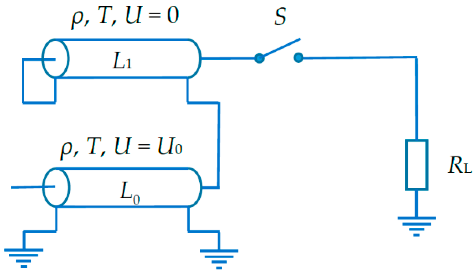
3.1.1. Double-Width Forming Line

Figure 3 shows a double-width forming line (DWFL) that comprises two series-connected lines L0, L1 that are equal in electrical length T and wave impedance ρ [23]. At the time of switch operation, line L0 is charged to U0, and line L1 is uncharged.
Obviously, when discharged, the DWFL equivalent impedance is 2ρ, and hence the load resistance is taken to be RL = 2ρ. A voltage pulse of amplitude U0/2 and duration 4T is provided at the load by the DWFL discharge circuit (Figure 4).
Immediately after operation of the switch (S), the circuit begins drawing a current I = U0/(RL + 2ρ) = U0/4ρ, which provides a voltage pulse amplitude UL = I∙RL = U0/2 at the load. Simultaneously, a voltage wave of amplitude Ub = I∙ρ = U0/4 propagates from right to left in the lines L0, L1. By the time t = T, the wave front in L0 reaches its open end at 3U0/4, and the wave front in L1 reaches the short-circuited end at –U0/4 and goes back with reversed polarity. By the time t = 2T, both waves return to the load such that the wave amplitude becomes U0/2 in L0 and zero in L1. For estimating the wave amplitudes in the two lines at the next time points, we can introduce their transmission and reflection coefficients k+ and k (to and from the load, respectively). For L0 and L1, these coefficients are equal and given by:
k+ = 2(RL + ρ)/[( RL + ρ) + ρ] = 3/2; and
k = [RL + ρ) − ρ]/[ RL + ρ) + ρ] = 1/2
Thus, considering that the L0 wave at 2T < t < 3T is divided into series-connected RL and ρ, we have (3/2)(2/3)(1/2)U0 = U0/2 at the load, a uniform decrease in the L0 wave amplitude from U0/2 at 2T to U0/4 at 3T, and U0/8 + U0/8 = U0/4 throughout the L1 line.
On the interval 3T < t < 4T, the L0 and L1 waves propagating to the load occupy increasingly less space, providing U0/2 at the load. Thus, the PFL comprising a short-circuited segment with a wave impedance ρ and electrical length T can double the load pulse width and halve the load power.

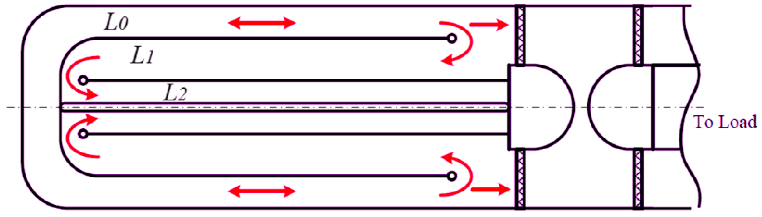
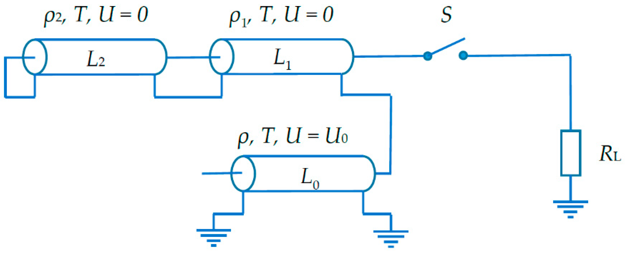
3.1.2. Triple-Width Forming Line

Figure 5 and Figure 6 show a triple-width forming line (TWFL) and its discharge circuit, respectively.
At the initial time point, L0 is charged to U0 while L1 and L2 are uncharged. The electrical lengths of L0, L1, and L2 are equal to T; the wave impedance of L0 is ρ. The coefficient of pulse extension k = 3 determines the load resistance RL = 3ρ. Considering that the load wave amplitude at 0 < t < T is U0/2 and that the current is I = U0/(RL + ρ + ρ1), the impedance of L1 can be estimated as ρ1 = 2ρ and the current as I = U0/6ρ. The backward wave amplitudes in L0 and L1 are –Iρ = −U0/6 and –Iρ1 = −U0/3, respectively. Thus, by the point t = T, the wave amplitude is −U0/3 in L1, zero in L2, and 5/6U0 in L0. The backward voltage wave in L0 reaches the plane with a circuit break and goes back with the same polarity.
The reflected wave amplitude U can be estimated in L2 for T < t < 2T by reasoning that the resulting amplitude at the load should be U0/2: UU0/3 + 2/3U0 = U0/2. We obtain U = U0/6. Thus, the voltage across L1 is UL1 = −U0/3 + U = −U0/6. However, this is possible at a definite reflection coefficient k = (ρ2ρ1)/(ρ2 + ρ1) whose value from −k − U0/3 = U0/6 is k = −1/2. Hence, ρ2 = ρ1/3 = 2ρ/3. By the time point t = 2T, the wave amplitude in L1 and in L2 is −U0/6, and in L0, it is 2/3U0. The next time points are only important for estimating the wave amplitudes in each line. For such estimation, the transmission and reflection coefficients at two boundaries are used. Omitting simple calculations, we obtain that by the point t = 3T, the wave amplitudes in L1 and L2 become equal to zero, and the wave amplitude in L0 is 1/2U0. Upon completion of the processes at 3T < t < 4T, the wave amplitudes in L1 and L2 are U0/6, and the wave amplitude in L0 is 1/3U0.
By the time point t = 5T, the wave amplitude in L1 and in L2 increases to U0/3, and in L0, it decreases to 1/6U0. Finally, at t = 6T, the voltage amplitudes in all lines are equal to zero. Table 1 presents the voltage amplitudes in each line at different time points.
Thus, the PFL configuration with two nested lines provides a rectangular voltage pulse of amplitude UL = U0/2 at a matched load and width t = 6T. The effective internal impedance of the TWFL is 3ρ.

3.1.3. Forming Line with k-Fold Extension

The possibility of two- and three-fold pulse lengthening and the similarity of DWFL and TWFL discharge processes suggest that a configuration with a higher integer factor of pulse extension k can be designed in which the number of additional lines is k − 1. In this case, the matched load resistance should increase to RL = . The impedance of L1 (additional line) is expressed as:
ρ1 = RLρ = (k − 1)ρ
The discharge current after the switch operation is I = U0/(RL + ρ1 + ρ) = U0/(2kρ). At the load, UL = IRL = U0/2. The backward wave amplitude in L0 is −Iρ = −U0/2k, and in L1, it is −Iρ1 = −U0(k − 1)/2k. The impedance of L2 is chosen for T < t < 2T from the condition that the load voltage is U0/2. Similarly, we estimate the impedance of L3 for 2T < t < 3T. Omitting intermediate calculations, we obtain:
ρ2= ρ1(k − 2)/k
The impedances of nested lines can be written in the form of a recurrence formula for k ≥ 3 as a generalization of the TWFL case with k = 3:
ρn = ρn−1{(kn)/(k + 2 − n)}
where n = 2, …, (k − 1), k ≥ 3.
It is noteworthy that the time behavior of voltage amplitudes in each line obeys rather simple laws that can easily be written, even from the data in Table 1. In particular, the voltage across the main line (L0) decreases by 1/2k from its initial value U0 on each interval T, and the voltage amplitude across the nested lines, being kept in the range (±1/k)∙U0, increases by 1/2k from its value at the previous stage.

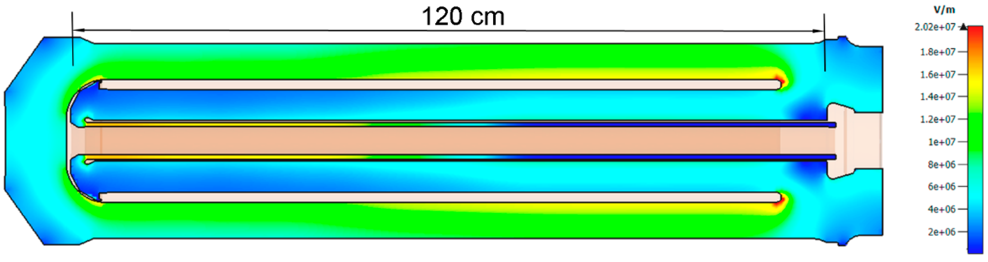
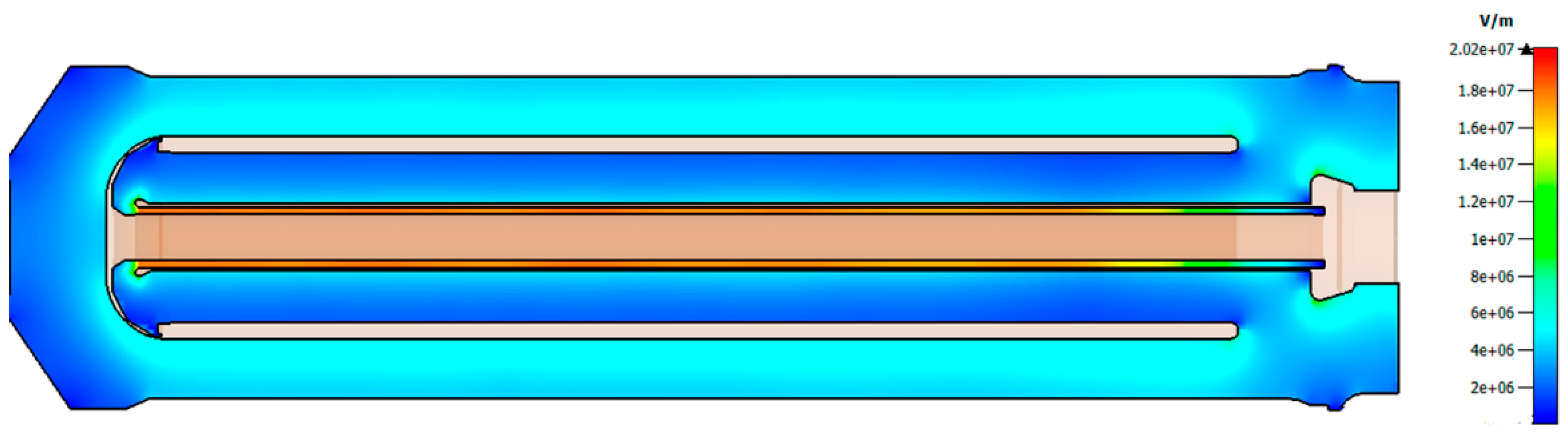
3.2. Simulation Results for TWFL

Our computations and experiments were performed for a dielectric with a relative permittivity ε = 2.25, which corresponded to transformer oil. The forming line was a TWFL with a length LFL = 120 cm and main-line conductor radii r2 = 15.6 cm, and r1 = 9.8 cm (Figure 7).
The discharge processes were simulated in the environment of CST Studio Suite software with schematic and 3D programs. For the TWFL parameters used, the impedance of the main line was ρ = 18.6 Ω. The switch was perfect, with a series-connected resistance equal to 18.6·3 = 55.8 Ω. According to Equations (7) and (8), the wave impedance of two nested lines should be ρ1 = 37.2 Ω and ρ2 = 12.4 Ω, respectively. In the simulation, the charging voltage was U0 = 794 kV, for which Equation (2) gave E = 0.175 MV/cm in the main line before discharging. According to electrostatic computations, the local field at the right electrode end, rounded to a radius of 0.8 cm, was no greater than 0.24 MV/cm.
In the experimental configuration, the gap of the inner coaxial deviated from its theoretical value such that ρ2 was 10.8 Ω (13% lower than the needed value for ρ2). Therefore, the same computations were performed for two configurations: theoretical (ideal) and experimental (real).
As can be seen from Figure 8, the voltage pulse in the real TWFL revealed two steps, deviating by no more than ±5% from the amplitude of the first third.
The simulation showed that the field strength at the electrodes of all coaxial lines and in all discharge stages corresponded to the time variation of their potential, exactly as given in Table 1. In particular, a significant issue can be the electrical strength of the inner gap of the line with the lowest impedance. Figure 9 demonstrates the field distribution at the time point 25 ns, which lay in the range 4T < t < 5T (T = 6 ns, see Table 1) and corresponded to the maximum potential difference in this part of the structure.
It is seen that the field in this TWFL part and at the rounded electrode end was not higher than 0.23 MV/cm. By considering the time of insulation exposure to the field and from the electrode surface areas (see Equation (5)), it could be concluded that the breakdown strength of the composite versions was approximately the same at the single PFL. What was intriguing is that this conclusion held for all inner electrode surfaces, despite the decrease in the transverse dimensions.

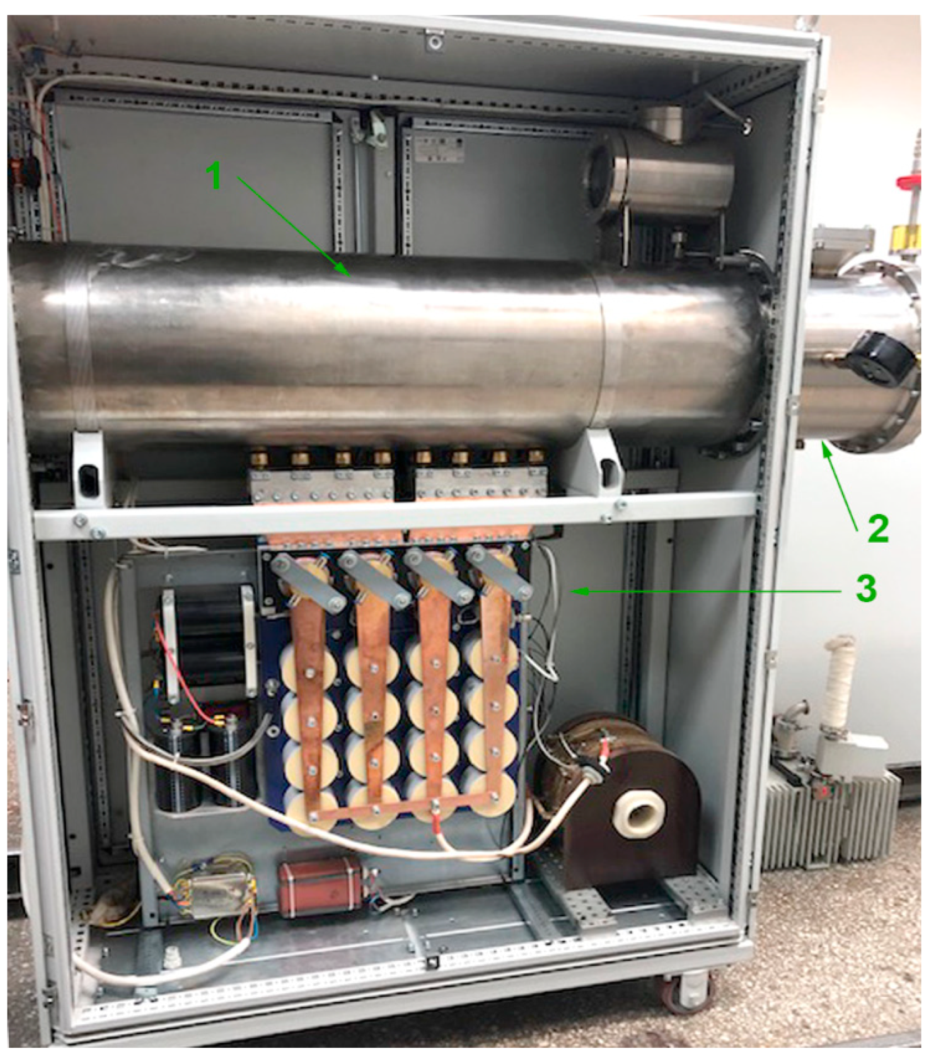
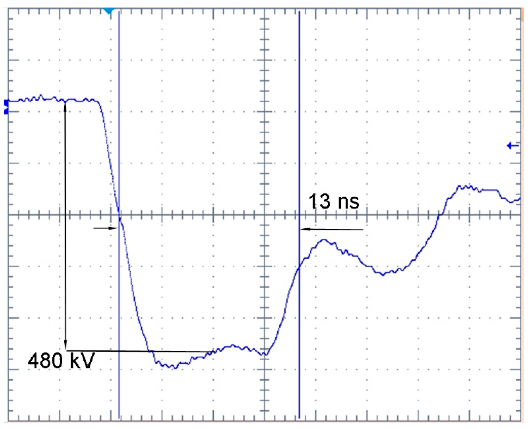
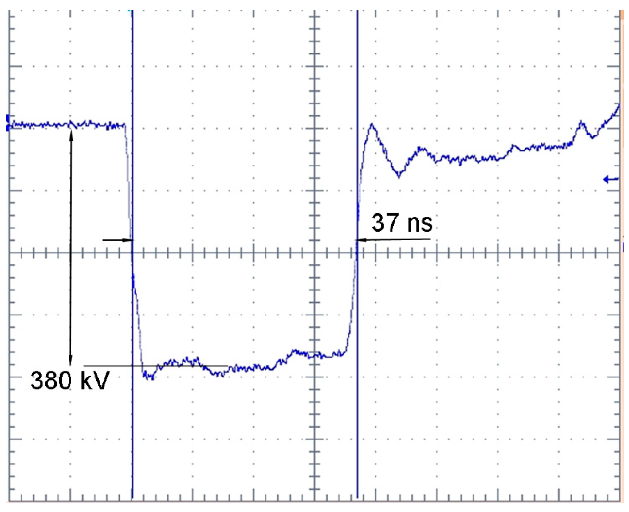
3.3. Laboratory Model of SINUS-Type Driver Based on TWFL

Figure 10 shows a laboratory model of a TWFL, which is a modification of the SINUS-330 setup based on a PFL of outer diameter 33 cm.
Originally, the SINUS-330 setup (a single FL with ρ0 ≈ 19 Ω and LFL ≈ 120 cm) was designed for experiments with Cherenkov-type microwave oscillators with a millimeter wavelength range. A typical waveform of the cathode voltage is shown in Figure 11.
Such research does not require high pulse repetition rates due to the use of impulse magnetic systems capable of providing a few pulses per minute for beam formation and transport. Compared to high repetition rates, the total number of pulses producible within a limited time is many (e.g., four) orders of magnitude lower. Therefore, the ratio E/Ebr may be increased; e.g., through increasing the charging voltage U0 by 30–40% [1,26]. In addition, no forced gas circulation is needed for the gas-gap switch (2) and the primary transformer circuit (3) is simplified as well.
With a fixed gap in the gas-gap switch, the charging voltage U0 could be varied from 580 to 670 kV, by varying the gas (nitrogen) pressure in the chamber.
With the original PFL (Figure 11), the voltage pulse duration across the load was ≈13 ns at a level of 0.5Umax. The voltage rise and fall times at 0.1–0.9Umax were about 4 ns. Thus, the pulse had a relatively short quasi-flat top of ≈10 ns. The load comprised high-voltage resistors with a total resistance of 80 Ω in the operating voltage range.
With its TWFL version at the same stored energy (Figure 12), the flat top of the pulse increased more than three times, and the voltage rise time decreased to about 3 ns. The voltage waveform was quite close to that observed in the simulation. The overshot, after a rise time of about 3 ns, was due to the presence of a low-impedance piercing of the initial part of the transmission line, which was not used in the simulation. The diode voltage amplitude UL ≈ 380 kV corresponded to the charging voltage (U0 ≈ 650 kV) and the value of the load (RL ≈ 80 Ω): UL = U0RL/(RL + ρeff), where ρeff ≈ 56 Ω. Equation (4) calculates the matching efficiency of the high-voltage driver and the load 96.9%.

4. Discussion

At equal stored energies, TWFLs (k = 3) have the same advantages as DWFLs over conventional PFLs [23] when high-resistance loads are used. The pulse extension allows one to decrease the driver dimensions at a specified load pulse duration, to increase the efficiency of matching the driver and the load, and to shorten the pulse rise time. It was supposed that the decrease in the voltage rise time was associated with the spark-channel dynamics, depending on the internal generator impedance [25].
Obviously, passing to longer high-voltage pulses needs a careful consideration of the reliability of the transmission-line insulation, including the solid-state vacuum insulator.
The proposed method of 4-fold voltage pulse extension (k = 4) has the prospect of increasing the duration of microwave pulses in the millimeter wavelength range, at moderate and low accelerating voltages (≈320 kV and less) when the e-beam diode impedance should measure ≈120 Ω or higher [12,17].

5. Conclusions

The proposed method allowed a many-fold extension of a high-voltage pulse by nesting additional lines into the free volume of the inner electrode of an ordinary PFL. For the first time, the general requirements for such lines have been formulated. The method has been given theoretical grounds. Its efficiency has been proven in a practice earlier for an X-band repetitively pulsed HPM relativistic backward wave oscillator [14] that was driven by a double-width pulse-forming line: for a fixed microwave pulse duration (20 ns), the total length of the source was decreased by approximately two times. The expectations of high efficiency of driver-load matching were confirmed in the described experiment with a triple-width forming line.

Author Contributions

Conceptualization, V.V.R. and A.S.S.; Data curation, V.V.R., A.S.S., P.V.V. and R.V.T.; Formal analysis, V.V.R., A.S.S. and R.V.T.; Investigation, R.V.T.; Methodology, V.V.R. and A.S.S.; Software, A.S.S. and R.V.T.; Validation, A.S.S., P.V.V. and R.V.T.; Visualization, A.S.S.; Writing—original draft, V.V.R. and A.S.S.; Writing—review and editing, V.V.R. All authors have read and agreed to the published version of the manuscript.

Funding

This research was supported by the Ministry of Science and Higher Education of the Russian Federation (No FWRM-2021-0002).

Conflicts of Interest

The authors declare no conflict of interest.

References

  1. Mesyats, G.A.; Korovin, S.D.; Gunin, A.V.; Gubanov, V.P.; Stepchenko, A.S.; Grishin, D.M.; Landl, V.F.; Alekseenko, P.I. Repetitively pulsed high-current accelerators with transformer charging of forming lines. Laser Part. Beams 2003, 21, 197–209. [Google Scholar] [CrossRef]
  2. Zhang, H.; Shu, T.; Liu, S.; Zhang, Z.; Song, L.; Zhang, H. A Compact Modular 5 GW Pulse PFN-Marx Generator for Driving HPM Source. Electronics 2021, 10, 545. [Google Scholar] [CrossRef]
  3. Lassale, F.; Morell, A.; Loyen, A.; Chanconie, T.; Roques, B.; Toury, M.; Vezinet, R. Development and test of a 400-kV PFN Marx with compactness and rise time optimization. IEEE Trans. Plasma Sci. 2018, 46, 3313–3319. [Google Scholar] [CrossRef]
  4. Krasik, Y.E.; Dunaevsky, A.; Krokhmal, A.; Felsteiner, J.; Gunin, A.V.; Pegel, I.V.; Korovin, S.D. Emission properties of different cathodes at E≤105 V/cm. J. Appl. Phys. 2001, 89, 2379–2399. [Google Scholar] [CrossRef]
  5. Afanas’ev, K.V.; Bykov, N.M.; Gubanov, V.P.; El’chaninov, A.A.; Klimov, A.I.; Korovin, S.D.; Rostov, V.V.; Stepchenko, A.S. A high-power periodic nanosecond pulse source of coherent 8-cm electromagnetic radiation. Tech. Phys. Lett. 2006, 32, 925–927. [Google Scholar] [CrossRef]
  6. Shafir, G.; Kreif, M.; Gleizer, J.Z.; Krasik, Y.E.; Gunin, A.V.; Kutenkov, O.P.; Pegel, I.V.; Rostov, V.V. Experimental research of different plasma cathodes for generation of high-current electron beams. J. Appl. Phys. 2015, 118, 193302. [Google Scholar] [CrossRef]
  7. Belomyttsev, S.Y.; Rostov, V.V.; Romanchenko, I.V.; Shunailov, S.A.; Kolomiets, M.D.; Mesyats, G.A.; Sharypov, K.A.; Shpak, V.G.; Ulmaskulov, M.R.; Yalandin, M.I. Magnetically insulated coaxial vacuum diode with partial space-charge-limited explosive emission from edge cathode. J. Appl. Phys. 2016, 119, 023304. [Google Scholar] [CrossRef]
  8. Belomyttsev, S.Y.; Korovin, S.D.; Pegel, I.V. Effect of the expanding explosive-emission centers plasma on the impedance of a high-current diode. IEEE Trans. Plasma Sci. 1999, 27, 1572–1577. [Google Scholar] [CrossRef]
  9. Rostov, V.V.; El’chaninov, A.A.; Klimov, A.I.; Konev, V.Y.; Romanchenko, I.V.; Sharypov, K.A.; Shunailov, S.A.; Ul’maskulov, M.R.; Yalandin, M.I. Phase control in parallel channels of shock-excited microwave nanosecond oscillators. IEEE Trans. Plasma Sci. 2013, 41, 2735–2741. [Google Scholar] [CrossRef]
  10. Yalandin, M.I.; Reutova, A.G.; Ulmaskulov, M.R.; Sharypov, K.A.; Shpak, V.G.; Shunailov, S.A.; Klimov, A.I.; Rostov, V.V.; Mesyats, G.A. Picosecond stability of injection of parallel high-current electron beams. Tech. Phys. Lett. 2009, 35, 804–807. [Google Scholar] [CrossRef]
  11. Rostov, V.V.; Elchaninov, A.A.; Romanchenko, I.V.; Yalandin, M.I. A coherent two-channel source of Cherenkov superradiance pulses. Appl. Phys. Lett. 2012, 100, 224102. [Google Scholar] [CrossRef]
  12. Rostov, V.V.; Elchaninov, A.A.; Romanchenko, I.V.; Shunailov, S.A.; Ulmaskulov, M.R.; Sharypov, K.A.; Shpak, V.G.; Rukin, S.N.; Yalandin, M.I. Two-channel generator of the 8-mm wavelength range for radiation with subgigawatt power level pulses. Radiophys. Quantum Electron. 2014, 56, 475–491. [Google Scholar] [CrossRef]
  13. Tot’meninov, E.M.; Vykhodsev, P.V.; Gunin, A.V.; Klimov, A.I.; Rostov, V.V. Increase in the energy efficiency of a pulsed-periodic relativistic backward wave oscillator with a modulating resonant reflector. Tech. Phys. 2014, 59, 428–433. [Google Scholar] [CrossRef]
  14. Rostov, V.V.; Tsygankov, R.V.; Vykhodsev, P.V.; Konev, V.Y.; Stepchenko, A.S. Stable operation of a repetitively pulsed X-band relativistic backward wave oscillator. IEEE Electron Device Lett. 2021, 42, 935–938. [Google Scholar] [CrossRef]
  15. Rostov, V.V.; Gunin, A.V.; Tsygankov, R.V.; Romanchenko, I.V.; Yalandin, M.I. Two-wave Cherenkov oscillator with moderately oversized slow-wave structure. IEEE Trans. Plasma Sci. 2017, 46, 33–42. [Google Scholar] [CrossRef]
  16. Sun, J.; Chen, C. Research on 3-GW repetitively operating relativistic backward wave oscillator. IEEE Trans. Plasma Sci. 2020, 48, 3535–3543. [Google Scholar] [CrossRef]
  17. Bratman, V.L.; Denisov, G.G.; Kolchugin, B.D.; Korovin, S.D.; Polevin, S.D.; Rostov, V.V. Powerful millimeter-wave generators based on the stimulated Cerenkov radiation of relativistic electron beams. Int. J. Infrared Millim. Waves. 1984, 5, 1311–1332. [Google Scholar] [CrossRef]
  18. Denisov, G.G.; Smorgonsky, A.V.; Gubanov, V.P.; Korovin, S.D.; Rostov, V.V.; Yalandin, M.I. Powerful electromagnetic millimeter-wave oscillations produced by stimulated scattering of microwave radiation by relativistic electron beams. Int. J. Infrared Millim. Waves. 1984, 5, 1389–1403. [Google Scholar] [CrossRef]
  19. Korovin, S.D.; Rostov, V.V.; Smorgonsky, A.V. Pulse-periodic relativistic carsinotron (in Russian). Izv. Vyssh. Uchebn. Zaved. Radiofiz. 1986, 29, 1278–1280. [Google Scholar]
  20. Gubanov, V.P.; Korovin, S.D.; Pegel, I.V.; Roitman, A.M.; Rostov, V.V.; Stepchenko, A.S. Compact 1000 pps high-voltage nanosecond pulse generator. IEEE Trans. Plasma Sci. 1997, 25, 258–265. [Google Scholar] [CrossRef]
  21. Gunin, A.V.; Landl’, V.F.; Korovin, S.D.; Mesyats, G.A.; Rostov, V.V. Long-lived explosive-emission cathode for high-power microwave generators. Tech. Phys. Lett. 1999, 25, 922–926. [Google Scholar] [CrossRef]
  22. Zhang, J.; Jin, Z.-X.; Yang, J.-H.; Zhong, H.-H.; Shu, T.; Zhang, J.-D.; Qian, B.-L.; Yuan, C.-W.; Li, Z.-Q.; Fan, Y.-W.; et al. Recent advance in long-pulse HPM sources with repetitive operation in S.-, C.-, and X-bands. IEEE Trans. Plasma Sci. 2011, 39, 1438–1445. [Google Scholar] [CrossRef]
  23. Liu, S.; Su, J.-C.; Zhang, X.; Pan, Y.-F.; Fan, H.-Y.; Fan, X.-L. A Tesla-type long-pulse generator with wide flat-top width based on double-width pulse-forming line. Laser Part. Beams 2018, 36, 115–120. [Google Scholar] [CrossRef]
  24. Eltchaninov, A.S.; Zagulov, F.Y.; Korovin, S.D.; Mesyats, G.A. Electron beam accelerator with high pulse recurrence frequency. In Proceedings of the 3rd International Topical Conference on High Power Electron and Ion Beams, Novosibirsk, Russia, 3–6 July 1979; pp. 191–197. [Google Scholar]
  25. Mesyats, G.A. Pulsed Power, 1st ed.; Springer: Boston, MA, USA, 2005. [Google Scholar] [CrossRef]
  26. Korovin, S.D.; Rostov, V.V.; Polevin, S.D.; Pegel, I.V.; Schamiloglu, E.; Fuks, M.I.; Barker, R.J. Pulsed power-driven high-power microwave sources. Proc. IEEE 2004, 92, 1082–1095. [Google Scholar] [CrossRef]
  27. Mesyats, G.A.; Korovin, S.D.; Rostov, V.V.; Shpak, V.G.; Yalandin, M.I. The RADAN series of compact pulsed power generators and their applications. Proc. IEEE 2004, 92, 1166–1179. [Google Scholar] [CrossRef]
  28. Zhang, Z.; Zhang, J.; Qian, B.; Liu, C.; Xun, T.; Zhang, H.; Liang, B. Compact rep-rate GW pulsed generator based on forming line with built-in high-coupling transformer. IEEE Trans. Plasma Sci. 2014, 42, 241–248. [Google Scholar] [CrossRef]
  29. Liu, S.F.; Zhang, Z.C.; Wang, Y.W.; Zhang, J.D.; Xiao, L.A.; Liang, B.; Li, D.G. Low-impedance high-power pulsed generator based on forming line with built-in Tesla transformer. Rev. Sci. Instrum. 2021, 92, 084705. [Google Scholar] [CrossRef]
  30. Martin, J.C. Nanosecond pulse techniques. Proc. IEEE 1992, 80, 934–945. [Google Scholar] [CrossRef]
  31. Ushakov, V.Y. Behavior of Liquids in Strong Electric Fields. In Impulse Breakdown of Liquids; Power Systems; Springer: Berlin/Heidelberg, Germany, 2007; pp. 1–51. [Google Scholar] [CrossRef]
  32. Korovin, S.D.; Rostov, V.V.; Tot’meninov, E.M. A relativistic backward wave oscillator with a modulating resonance reflector. Tech. Phys. Lett. 2005, 31, 411–413. [Google Scholar] [CrossRef]
  33. Tot’meninov, E.M.; Klimov, A.I.; Kurkan, I.K.; Polevin, S.D.; Rostov, V.V. Repetitively pulsed relativistic BWO with enhanced mechanical frequency tunability. IEEE Trans. Plasma Sci. 2008, 36, 2609–2612. [Google Scholar] [CrossRef]
  34. Liu, S.; Su, J.; Fan, X. Note: A high-energy-density tesla-type pulse generator with novel insulating oil. Rev. Sci. Instrum. 2017, 88, 096101. [Google Scholar] [CrossRef] [PubMed]
  35. Martin, D.; Wang, Z.D. Statistical analysis of the AC breakdown voltages of ester based transformer oils. IEEE Trans. Dielectr. Electr. Insul. 2008, 15, 1044–1050. [Google Scholar] [CrossRef]
  36. Ulmaskulov, M.R.; Pedos, M.S.; Rukin, S.N.; Sharypov, K.A.; Shpak, V.G.; Shunailov, S.A.; Yalandin, M.I.; Romanchenko, I.V.; Rostov, V.V. High repetition rate multi-channel source of high-power rf-modulated pulses. Rev. Sci. Instrum. 2015, 86, 074702. [Google Scholar] [CrossRef] [PubMed]
  37. Romanchenko, I.V.; Ulmaskulov, M.R.; Sharypov, K.A.; Shunailov, S.A.; Shpak, V.G.; Yalandin, M.I.; Pedos, M.S.; Rukin, S.N.; Konev, V.Y.; Rostov, V.V. Four channel high power rf source with beam steering based on gyromagnetic nonlinear transmission lines. Rev. Sci. Instrum. 2017, 88, 054703. [Google Scholar] [CrossRef]
Figure 1. Geometry of PFL with built in Tesla transformer. The main part of the length LFL is a Tesla transformer range (hatched area shows the magnetic cores). An additional piece of coaxial line L0 can be used to increase the formed voltage pulse width.
Electronics 11 00406 g001
Figure 2. Equivalent discharge circuit of single coaxial PFL.
Electronics 11 00406 g002
Figure 3. Double width forming line.
Electronics 11 00406 g003
Figure 4. DWFL discharge circuit.
Electronics 11 00406 g004
Figure 5. Simplified TWFL schematic.
Electronics 11 00406 g005
Figure 6. TWFL discharge circuit.
Electronics 11 00406 g006
Figure 7. Simulation results on field distribution in real TWFL at discharge point of 10 ns.
Electronics 11 00406 g007
Figure 8. Computed voltage pulse shapes in ideal TWFL with ρ2 = 12.4 Ω (blue) and real TWFL with ρ2 = 10.8 Ω (red).
Electronics 11 00406 g008
Figure 9. Field distribution in TWFL at discharge point 25 ns.
Electronics 11 00406 g009
Figure 10. TWFL-based SINUS driver for low pulse repetition rates: 1–Tesla transformer with TWFL; 2–gas-gap switch chamber; 3–primary transformer circuit with thyristors, capacitors, and other elements.
Electronics 11 00406 g010
Figure 11. Voltage waveform at the resistive load for single PFL charged to −600 kV (time base 4 ns/div).
Electronics 11 00406 g011
Figure 12. Voltage waveform across resistive load for TWFL charged to −650 kV (time base 10 ns/div).
Electronics 11 00406 g012
Table 1. Voltage amplitudes in TWFL.
tUL0/U0UL1/U0UL2/U0
0100
T5/6−1/30
2T2/3−1/6−1/6
3T1/200
4T1/31/61/6
5T1/61/31/3
6T000
Publisher’s Note: MDPI stays neutral with regard to jurisdictional claims in published maps and institutional affiliations.

