
Photovoltaic-Battery-Ultracapacitor-Diesel Hybrid Generation System for Mobile Hospital Energy Supply

 ,
,  ,
,  ,
, 
Abstract
1. Introduction
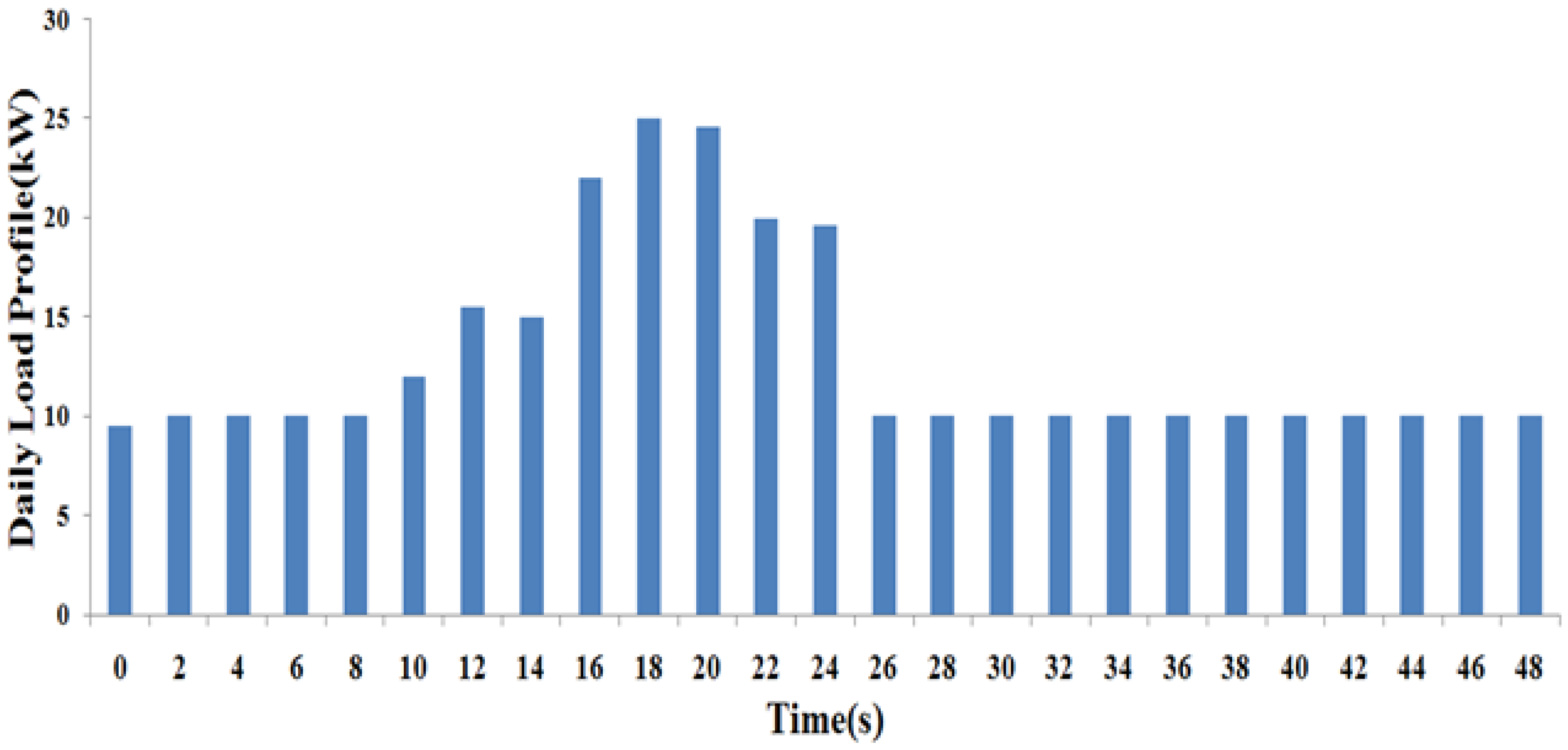
2. Power Sizing of Mobile Hospital
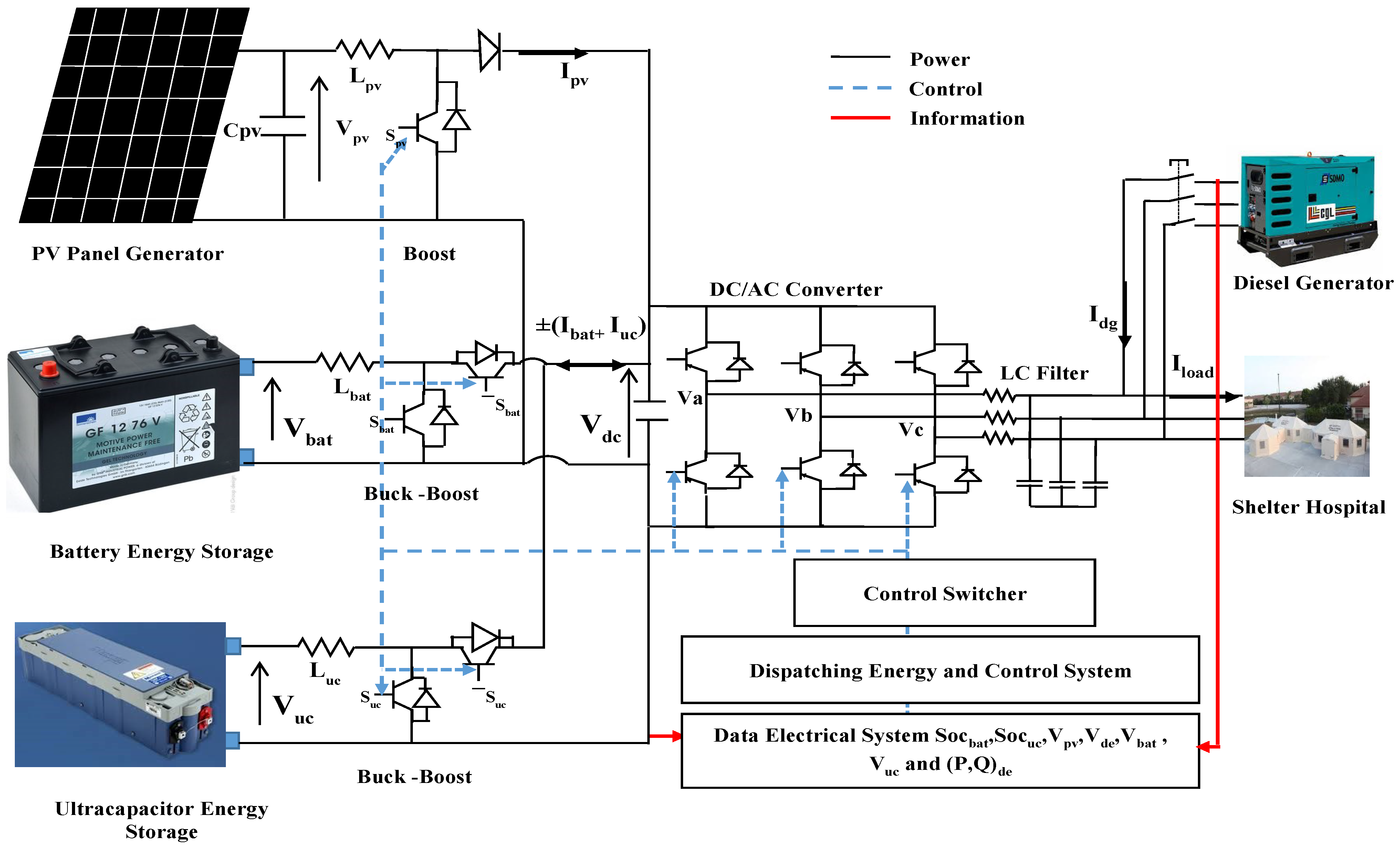
3. Hybrid System Structure
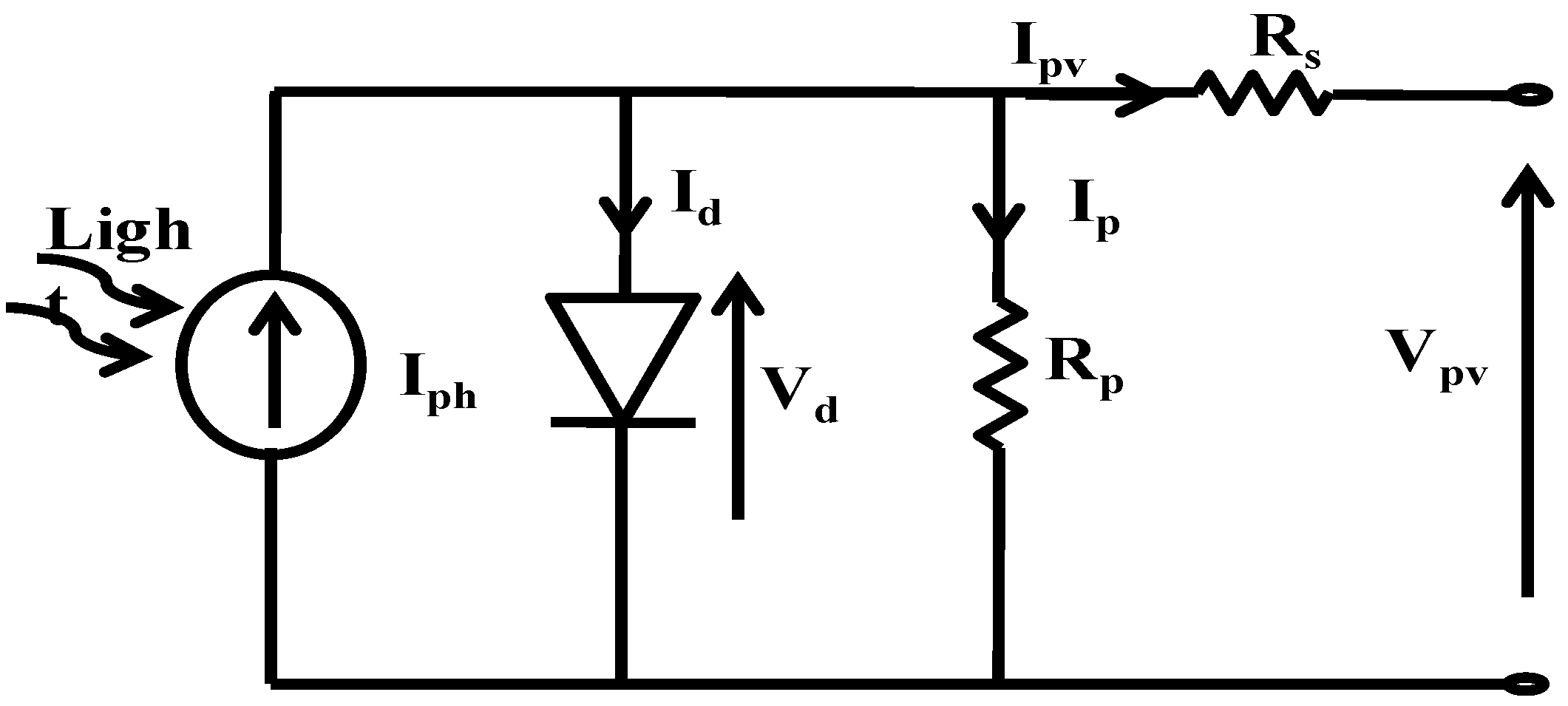
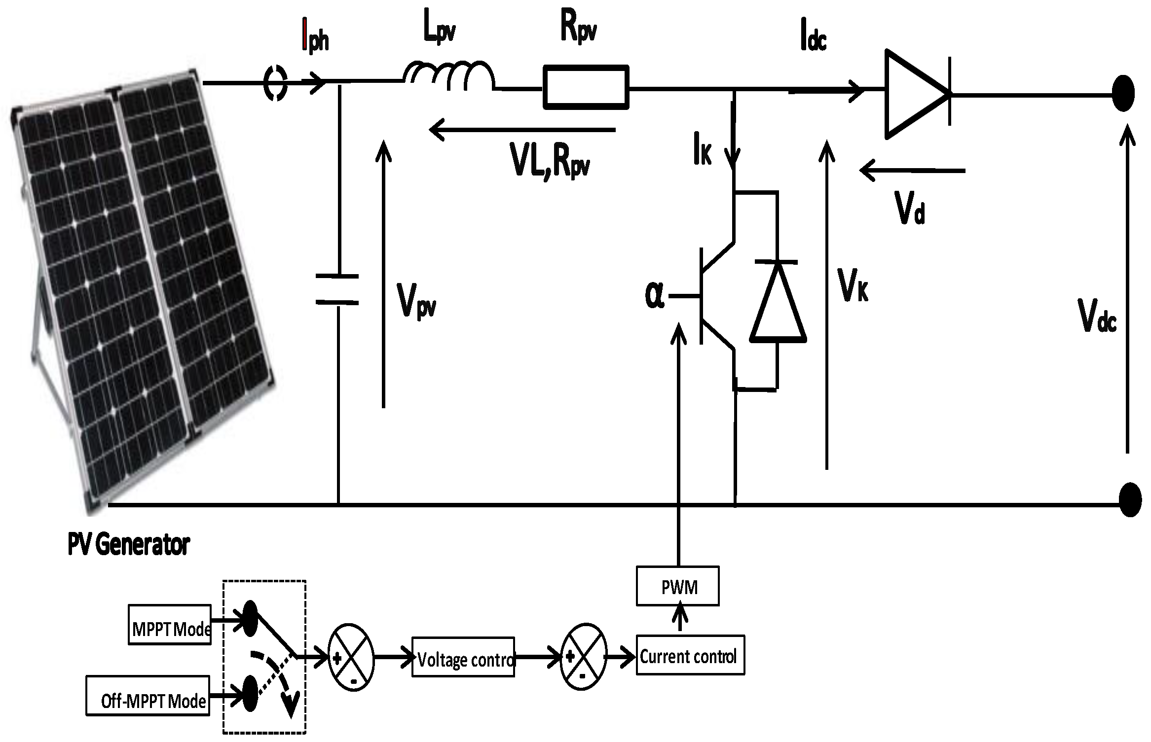
3.1. PV Generator
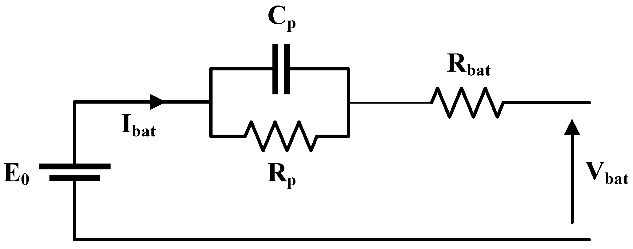
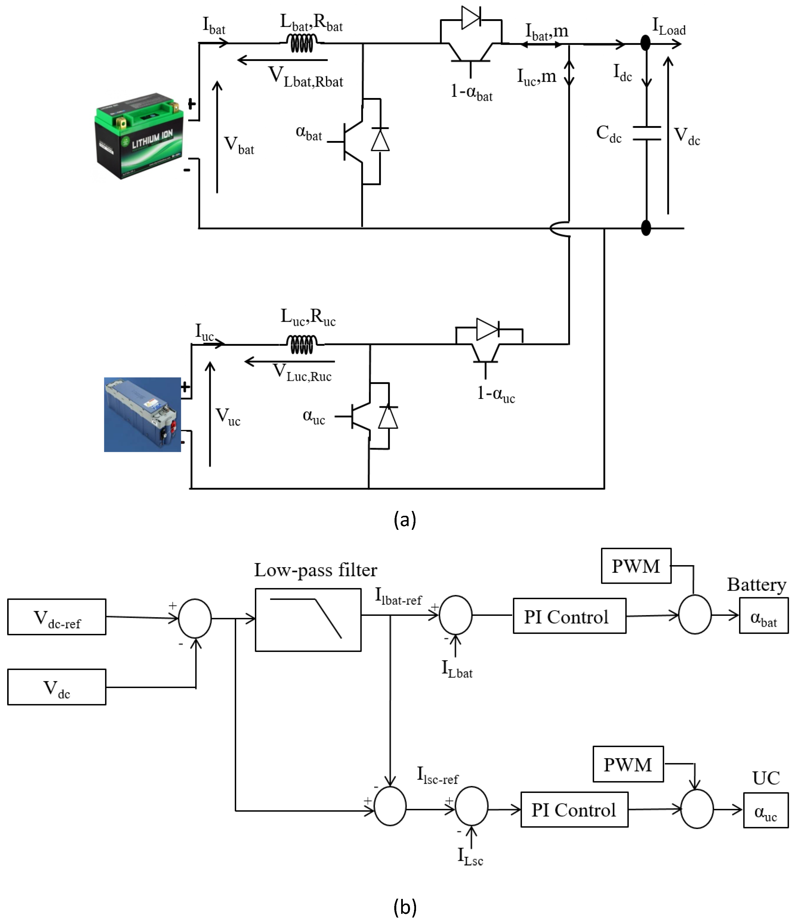
3.2. Battery
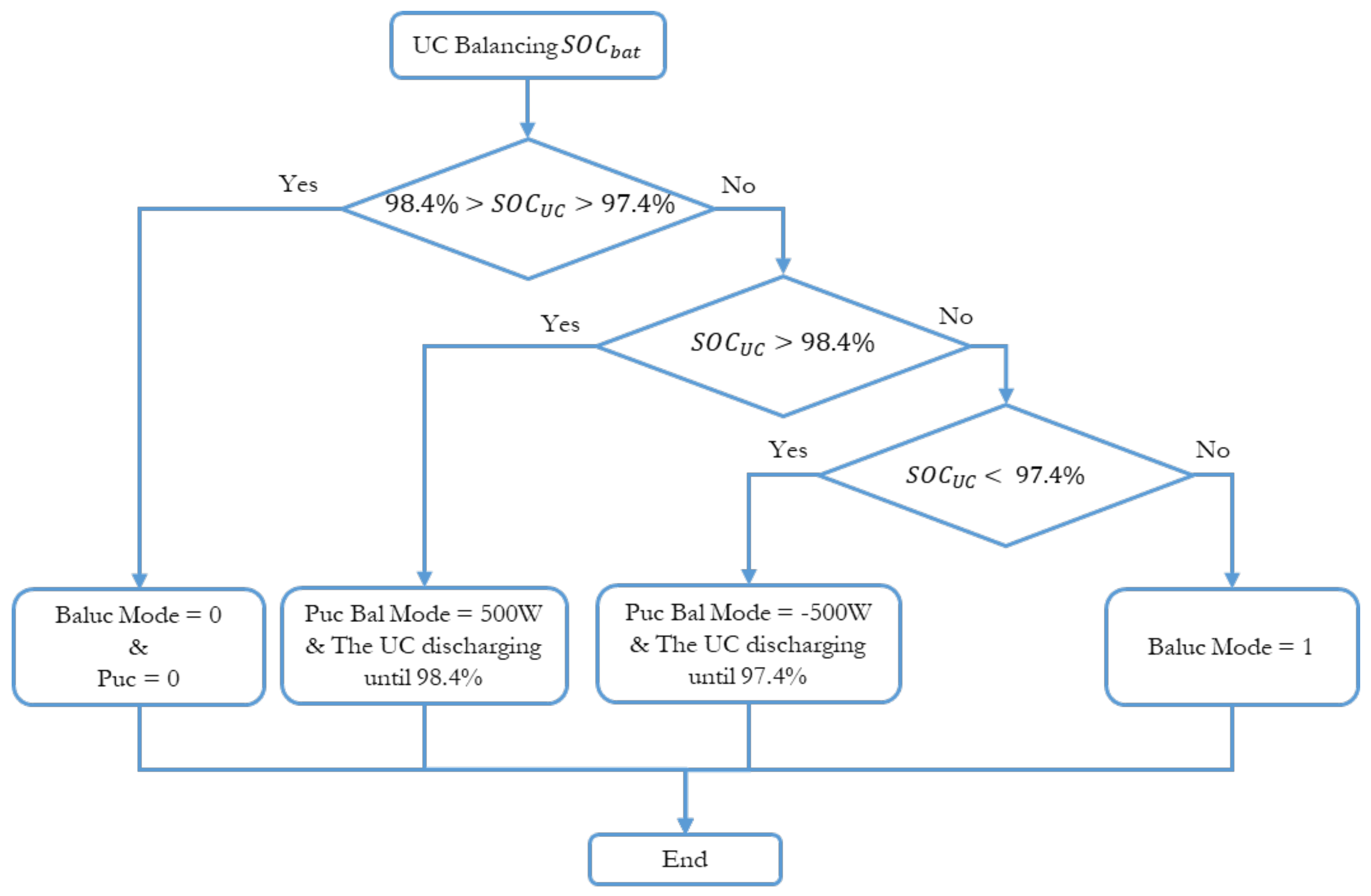
3.3. Ultracapacitor
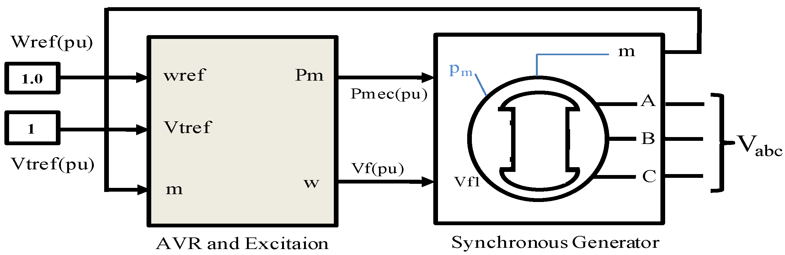
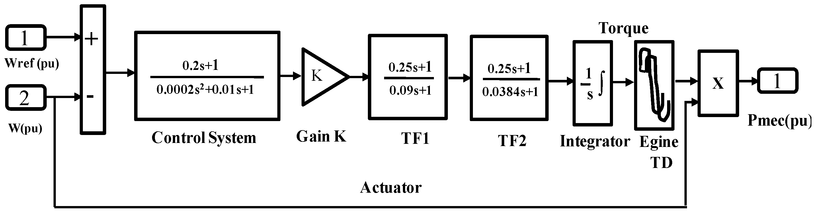
3.4. Diesel Generator
4. Power Management of Hybrid System
4.1. PV Generator Control
4.2. DC Bus Control
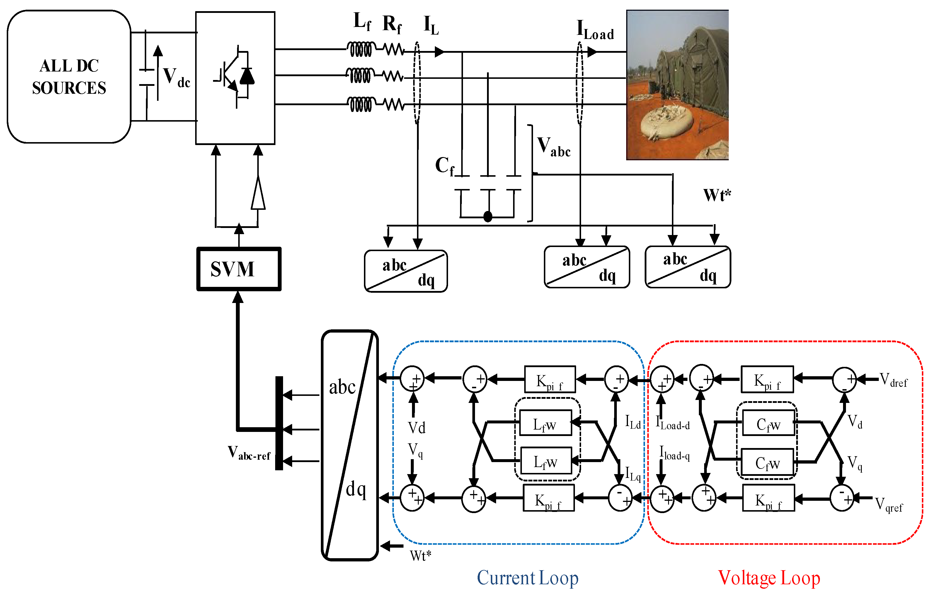
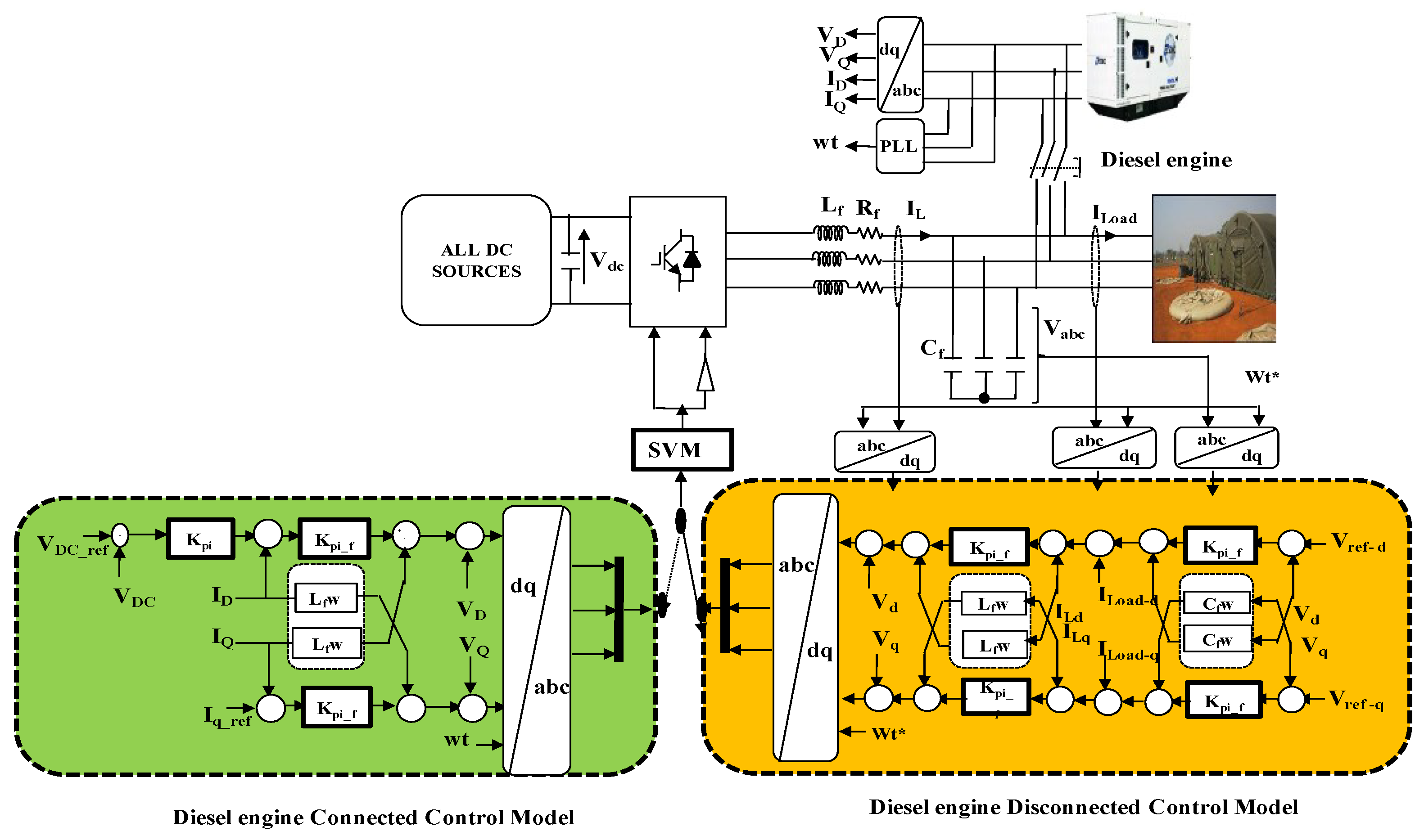
4.3. AC Bus Control
4.3.1. Grid-Disconnected Mode (Off-Grid)
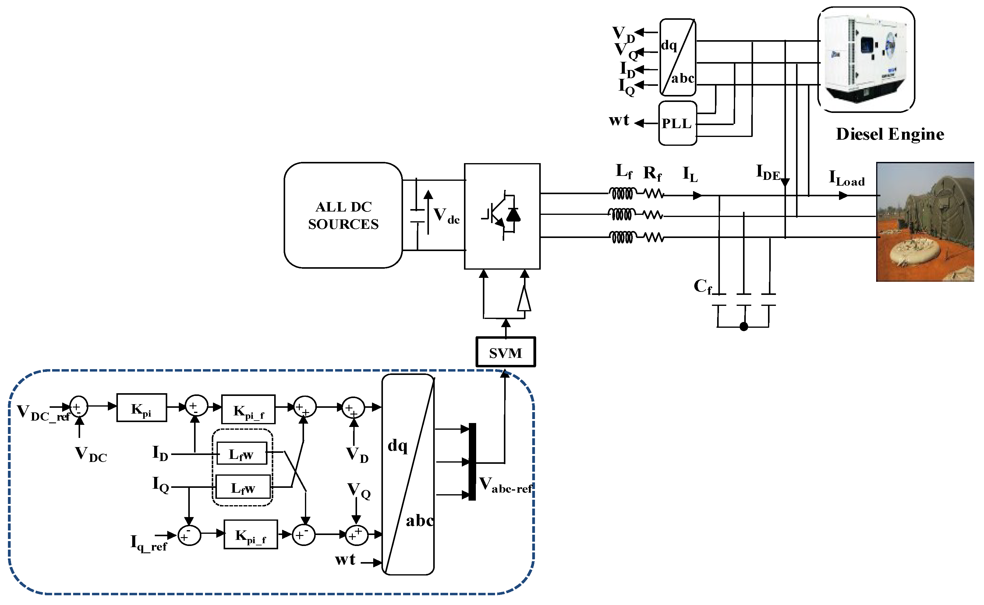
4.3.2. Grid-Connected Mode
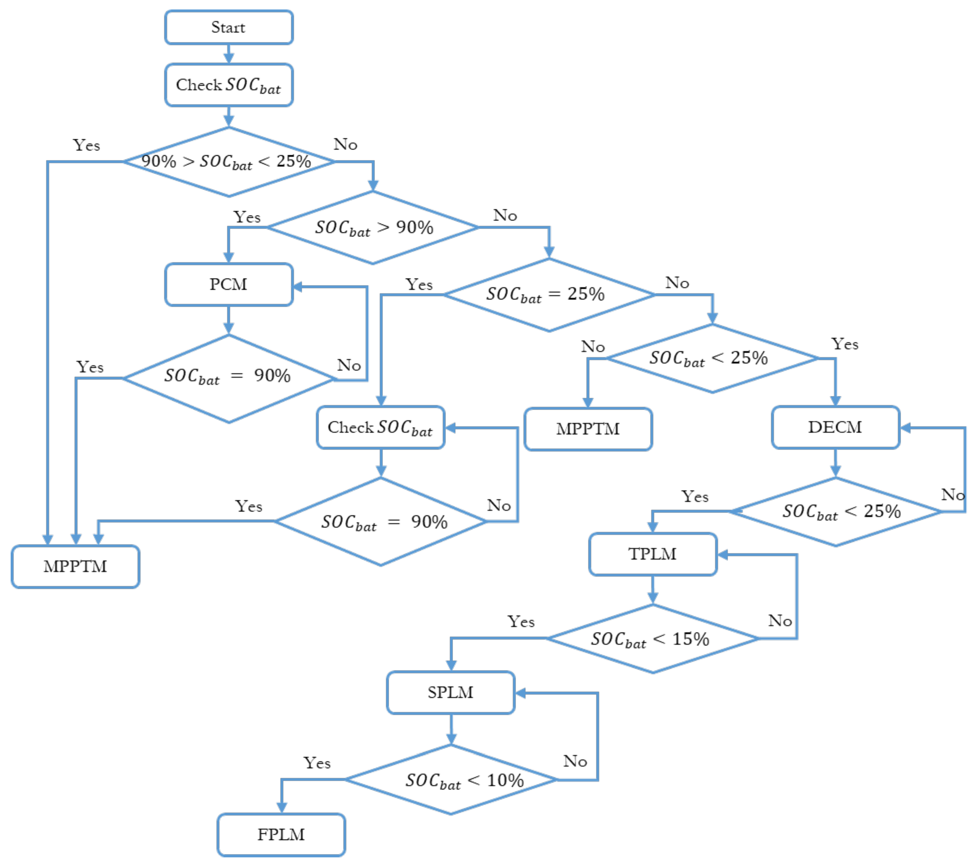
5. Power Management Strategy
5.1. Diesel Engine Disconnected Mode (DEDM)
5.1.1. Power Curtailment Mode (PCM)
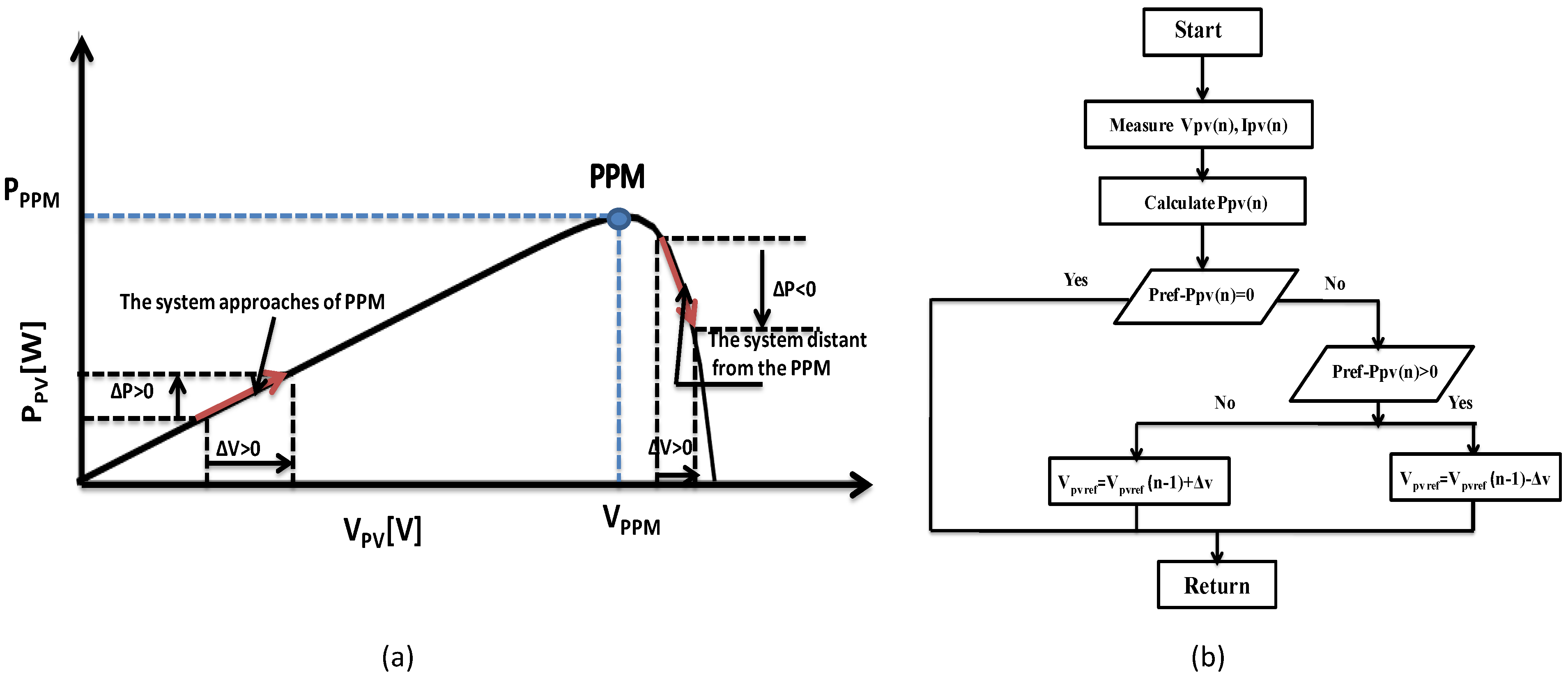
5.1.2. Maximum Power Point Tracking Mode (MPPTM)
5.2. Diesel Engine Connected Mode (DECM)
5.3. First Priority Load Mode (FPLM)
5.4. Second Priority Load Mode (SPLM)
5.5. Third Priority Load Mode (TPLM)
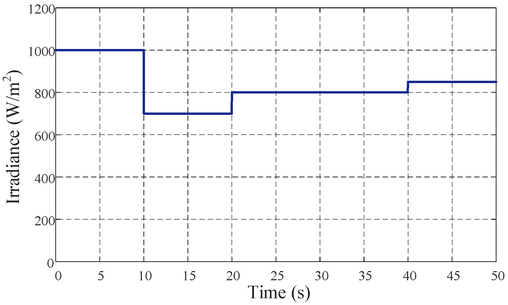
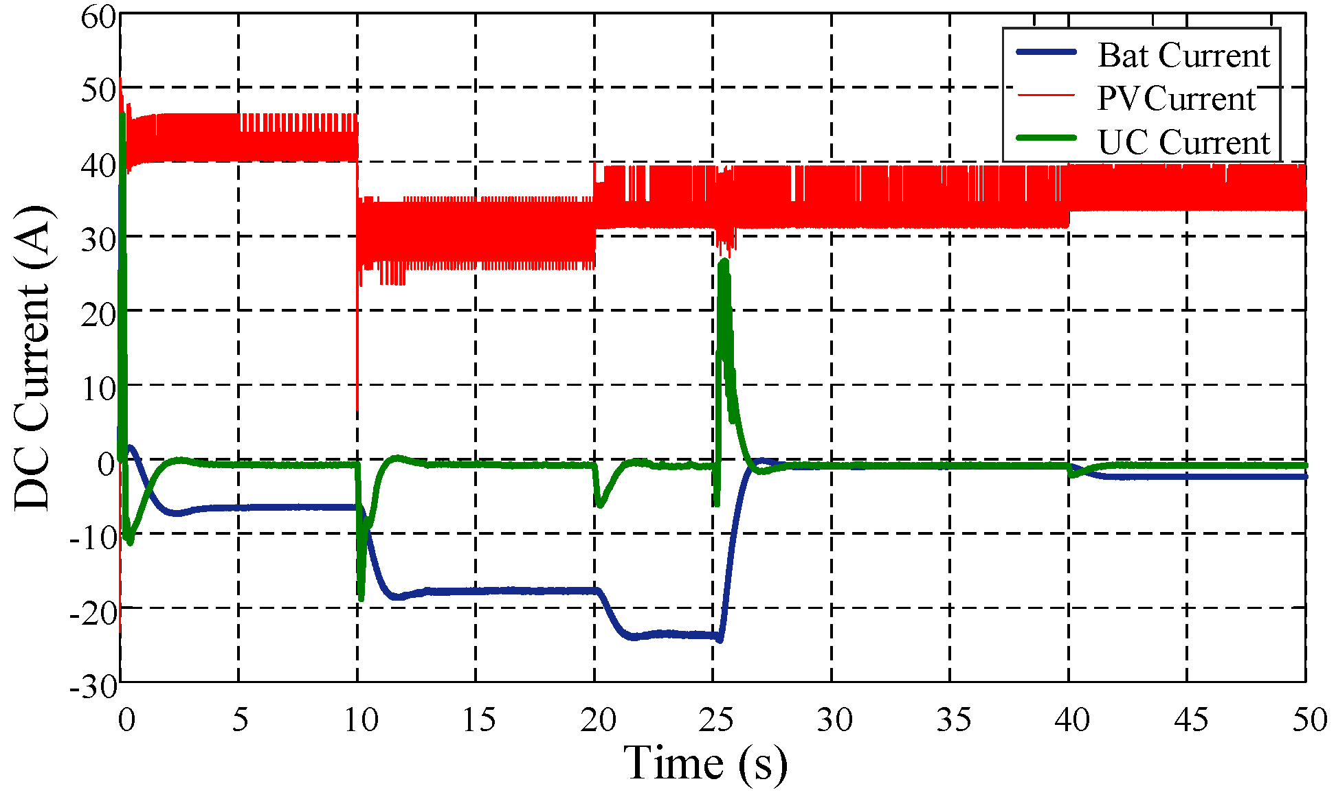
6. Results and Discussion
7. Conclusions
Author Contributions
Funding
Data Availability Statement
Conflicts of Interest
References
- Ouma, P.O.; Maina, J.; Thuranira, P.N.; Macharia, P.M.; Alegana, V.A.; English, M.; Okiro, E.A.; Snow, R.W. Access to emergency hospital care provided by the public sector in sub-Saharan Africa in 2015: A geocoded inventory and spatial analysis. Lancet Glob. Health 2018, 6, 342–350. [Google Scholar] [CrossRef]
- Juran, S.; Broer, P.N.; Klug, S.J.; Snow, R.C.; Okiro, E.A.; Ouma, P.O.; Snow, R.W.; Tatem, A.J.; Meara, J.G.; Alegana, V.A. Geospatial mapping of access to timely essential surgery in sub-Saharan Africa. BMJ Glob. Health 2018, 3, e000875. [Google Scholar] [CrossRef] [PubMed]
- Bakowski, J. A mobile hospital–its advantages and functional limitations. Int. J. Saf. Secur. Eng. 2016, 6, 746–754. [Google Scholar] [CrossRef]
- Issa, M.; Ibrahim, H.; Hosni, H.; Ilinca, A.; Rezkallah, M. Effects of Low Charge and Environmental Conditions on Diesel Generators Operation. Eng 2020, 1, 137–152. [Google Scholar] [CrossRef]
- Raghuwanshi, S.S.; Arya, R. Reliability evaluation of stand-alone hybrid photovoltaic energy system for rural healthcare centre. Sustain. Energy Technol. Assess. 2020, 37, 100624. [Google Scholar] [CrossRef]
- Aussel, D.; Neveu, P.; Tsuanyo, D.; Azoumah, Y. On the equivalence and comparison of economic criteria for energy projects: Application on PV/diesel hybrid system optimal design. Energy Convers. Manag. 2018, 163, 493–506. [Google Scholar] [CrossRef]
- Zia, M.F.; Elbouchikhi, E.; Benbouzid, M. An energy management system for hybrid energy sources-based stand-alone marine microgrid. In IOP Conference Series: Earth and Environmental Science; IOP Publishing: Bristol, UK, 2019; Volume 322, p. 012001. [Google Scholar]
- Sabihuddin, S.; Kiprakis, A.E.; Mueller, M. A numerical and graphical review of energy storage technologies. Energies 2015, 8, 172–216. [Google Scholar] [CrossRef]
- Haidl, P.; Buchroithner, A.; Schweighofer, B.; Bader, M.; Wegleiter, H. Lifetime analysis of energy storage systems for sustainable transportation. Sustainability 2019, 11, 6731. [Google Scholar] [CrossRef]
- Agbli, K.S.; Hilairet, M.; Gustin, F. Real-Time Control Based on a CAN-Bus of Hybrid Electrical Systems. Energies 2020, 13, 4502. [Google Scholar] [CrossRef]
- González, A.G.; García-Sanz-Calcedo, J.; Salgado, D.R. A quantitative analysis of final energy consumption in hospitals in Spain. Sustain. Cities Soc. 2018, 36, 169–175. [Google Scholar] [CrossRef]
- Mohamed, M.A.; Eltamaly, A.M.; Alolah, A.I. Sizing and techno-economic analysis of stand-alone hybrid photovoltaic/wind/diesel/battery power generation systems. J. Renew. Sustain. Energy 2015, 7, 063128. [Google Scholar] [CrossRef]
- Islam, S.M.; Nayar, C.V.; Abu-Siada, A.; Hasan, M.M. Power Electronics for Renewable Energy Sources. In Power Electronics Handbook; Elsevier: Amsterdam, The Netherlands, 2018; pp. 783–827. [Google Scholar]
- Lagrange, A.; de Simón-Martín, M.; González-Martínez, A.; Bracco, S.; Rosales-Asensio, E. Sustainable microgrids with energy storage as a means to increase power resilience in critical facilities: An application to a hospital. Int. J. Electr. Power Energy Syst. 2020, 119, 105865. [Google Scholar] [CrossRef]
- Alonso, J.B.; Sandwell, P.; Nelson, J. The potential for solar-diesel hybrid mini-grids in refugee camps: A case study of Nyabiheke camp, Rwanda. Sustain. Energy Technol. Assess. 2021, 44, 101095. [Google Scholar]
- Jahangir, M.H.; Cheraghi, R. Economic and environmental assessment of solar-wind-biomass hybrid renewable energy system supplying rural settlement load. Sustain. Energy Technol. Assess. 2020, 42, 100895. [Google Scholar] [CrossRef]
- Elia, S.; Santantonio, A. Fire risk in MTBF evaluation for UPS system. Adv. Electr. Electron. Eng. 2016, 14, 189–195. [Google Scholar] [CrossRef]
- Elia, S.; Santini, E.; Tobia, M. Comparison between different electrical configurations of emergency diesel generators for redundancy and reliability improving. Period. Polytech. Electr. Eng. Comput. Sci. 2018, 62, 144–148. [Google Scholar] [CrossRef]
- Boccaletti, C.; Elia, S.; Salas M, E.; Pasquali, M. High reliability storage systems for genset cranking. J. Energy Storage 2020, 29, 101336. [Google Scholar] [CrossRef]
- Mutarraf, M.U.; Terriche, Y.; Niazi, K.A.K.; Khan, F.; Vasquez, J.C.; Guerrero, J.M. Control of hybrid diesel/PV/battery/ultra-capacitor systems for future shipboard microgrids. Energies 2019, 12, 3460. [Google Scholar] [CrossRef]
- Tah, A.; Das, D. Operation of small hybrid autonomous power generation system in isolated, interconnected and grid connected modes. Sustain. Energy Technol. Assess. 2016, 17, 11–25. [Google Scholar] [CrossRef]
- Yin, C.; Wu, H.; Locment, F.; Sechilariu, M. Energy management of DC microgrid based on photovoltaic combined with diesel generator and supercapacitor. Energy Convers. Manag. 2017, 132, 14–27. [Google Scholar] [CrossRef]
- Gassab, S.; Radjeai, H.; Mekhilef, S.; Choudar, A. Power management and coordinated control of standalone active PV generator for isolated agriculture area-case study in the South of Algeria. J. Renew. Sustain. Energy 2019, 11, 015305. [Google Scholar] [CrossRef]
- Kim, Y.S.; Kim, E.S.; Moon, S.I. Frequency and voltage control strategy of standalone microgrids with high penetration of intermittent renewable generation systems. IEEE Trans. Power Syst. 2015, 31, 718–728. [Google Scholar] [CrossRef]
- Choudar, A.; Boukhetala, D.; Barkat, S.; Brucker, J.M. A local energy management of a hybrid PV-storage based distributed generation for microgrids. Energy Convers. Manag. 2015, 90, 21–33. [Google Scholar] [CrossRef]
- Wen, S.; Wang, S.; Liu, G.; Liu, R. Energy management and coordinated control strategy of PV/HESS AC microgrid during islanded operation. IEEE Access 2018, 7, 4432–4441. [Google Scholar] [CrossRef]
- Klugmann-Radziemska, E.; Ostrowski, P. Chemical treatment of crystalline silicon solar cells as a method of recovering pure silicon from photovoltaic modules. Renew. Energy 2010, 35, 1751–1759. [Google Scholar] [CrossRef]
- Huang, W.H.; Shin, W.J.; Wang, L.; Sun, W.C.; Tao, M. Strategy and technology to recycle wafer-silicon solar modules. Sol. Energy 2017, 144, 22–31. [Google Scholar] [CrossRef]
- Nayak, P.K.; Mahesh, S.; Snaith, H.J.; Cahen, D. Photovoltaic solar cell technologies: Analysing the state of the art. Nat. Rev. Mater. 2019, 4, 269–285. [Google Scholar] [CrossRef]
- Tang, K.H.; Chao, K.H.; Chao, Y.W.; Chen, J.P. Design and implementation of a simulator for photovoltaic modules. Int. J. Photoenergy 2012, 2012, 368931. [Google Scholar] [CrossRef]
- Widyolar, B.; Jiang, L.; Brinkley, J.; Hota, S.K.; Ferry, J.; Diaz, G.; Winston, R. Experimental performance of an ultra-low-cost solar photovoltaic-thermal (PVT) collector using aluminum minichannels and nonimaging optics. Appl. Energy 2020, 268, 114894. [Google Scholar] [CrossRef]
- Sarita, K.; Devarapalli, R.; Rai, P. Modeling and control of dynamic battery storage system used in hybrid grid. Energy Storage 2020, 2, e146. [Google Scholar] [CrossRef]
- Li, Y.; Vilathgamuwa, M.; Farrell, T.; Tran, N.T.; Teague, J. A physics-based distributed-parameter equivalent circuit model for lithium-ion batteries. Electrochim. Acta 2019, 299, 451–469. [Google Scholar] [CrossRef]
- Tran, M.K.; DaCosta, A.; Mevawalla, A.; Panchal, S.; Fowler, M. Comparative study of equivalent circuit models performance in four common lithium-ion batteries: LFP, NMC, LMO, NCA. Batteries 2021, 7, 51. [Google Scholar] [CrossRef]
- Tran, M.K.; Mathew, M.; Janhunen, S.; Panchal, S.; Raahemifar, K.; Fraser, R.; Fowler, M. A comprehensive equivalent circuit model for lithium-ion batteries, incorporating the effects of state of health, state of charge, and temperature on model parameters. J. Energy Storage 2021, 43, 103252. [Google Scholar] [CrossRef]
- Logerais, P.O.; Camara, M.; Riou, O.; Djellad, A.; Omeiri, A.; Delaleux, F.; Durastanti, J. Modeling of a supercapacitor with a multibranch circuit. Int. J. Hydrogen Energy 2015, 40, 13725–13736. [Google Scholar] [CrossRef]
- Helseth, L.E. Modelling supercapacitors using a dynamic equivalent circuit with a distribution of relaxation times. J. Energy Storage 2019, 25, 100912. [Google Scholar] [CrossRef]
- Sakamoto, O. An example of a diesel generator model with fluctuating engine torque for transient analysis using XTAP. J. Int. Counc. Electr. Eng. 2016, 6, 31–35. [Google Scholar] [CrossRef][Green Version]
- Mishra, S.; Ramasubramanian, D. Improving the small signal stability of a PV-DE-dynamic load-based microgrid using an auxiliary signal in the PV control loop. IEEE Trans. Power Syst. 2014, 30, 166–176. [Google Scholar] [CrossRef]
- Christopher, I.W.; Ramesh, R. Comparative study of P&O and InC MPPT algorithms. Am. J. Eng. Res. (AJER) 2013, 2, 402–408. [Google Scholar]
- Carrasco, J.A.; de Quirós, F.G.; Alavés, H.; Navalón, M. An analog maximum power point tracker with pulsewidth modulator multiplication for a solar array regulator. IEEE Trans. Power Electron. 2018, 34, 8808–8815. [Google Scholar] [CrossRef]
- Bhattacharyya, S.; Samanta, S.; Mishra, S. Steady Output and Fast Tracking MPPT (SOFT-MPPT) for P&O and InC Algorithms. IEEE Trans. Sustain. Energy 2020, 12, 293–302. [Google Scholar]
- Tao, Y.; Liu, Q.; Deng, Y.; Liu, X.; He, X. Analysis and mitigation of inverter output impedance impacts for distributed energy resource interface. IEEE Trans. Power Electron. 2014, 30, 3563–3576. [Google Scholar] [CrossRef]
- Ramezani, M.; Li, S.; Sun, Y. DQ-reference-frame based impedance and power control design of islanded parallel voltage source converters for integration of distributed energy resources. Electr. Power Syst. Res. 2019, 168, 67–80. [Google Scholar] [CrossRef]
- Kosari, M.; Hosseinian, S.H. Decentralized reactive power sharing and frequency restoration in islanded microgrid. IEEE Trans. Power Syst. 2016, 32, 2901–2912. [Google Scholar] [CrossRef]
- Mazhar-Ul-Haq, S.; Ram, S.; Subramanyam, J. Voltage Oriented Control (VOC) Of The PWM Rectifier Using Active Filtering Function. Int. J. Eng. Technol. 2018, 7, 90–93. [Google Scholar] [CrossRef]
- Zamani, M.H.; Riahy, G.H.; Abedi, M. Rotor-speed stability improvement of dual stator-winding induction generator-based wind farms by control-windings voltage oriented control. IEEE Trans. Power Electron. 2015, 31, 5538–5546. [Google Scholar] [CrossRef]


| Basic Equipment | ||||||
|---|---|---|---|---|---|---|
| Equipment | Power (W) | Hours Used per Day (h) | Energy per Day (Wh/Day) | First Priority | Second Priority | Third Priority |
| Lights (fluorescent) | 11 | 8 | 88 | x | ||
| Mobile phone charger | 5–20 | 8 | 40–160 | x | ||
| Ceiling fan (DC, AC) | 30–100 | 8 | 300–800 | x | ||
| Water pump | 100 | 6 | 600 | x | ||
| Computer | 15–200 | 4.5 | 67.5–900 | x | ||
| Portable electrical heater | 1000–1500 | 2 | 2000–3000 | x | ||
| Radio | 2–30 | 8 | 16–240 | x | ||
| Printer (ink, laser) | 65–1000 | 2 | 130–2000 | x | ||
| Small waste autoclave | 600–6000 | 1 | 600–6000 | x | ||
| Medical Equipment | ||||||
| Sterilizer (steam) | 500–1560 | 2 | 1000–3200 | x | ||
| Suction | 24 | 10 | 240 | x | ||
| Pulse Oximetry | 24 | 3 | 72 | x | ||
| Reverse-osmosis Water purifier | 260-570 | 7 | 1820–2590 | x | ||
| X-ray machine (dental) | 200 | 1 | 200 | x | ||
| X-ray machine (portable and fixed) | 300–2000 | 2 | 600–4000 | x | ||
| Mechanical ventilator | 608 | 3 | 1824 | x | ||
| Ultrasound scanner | 75 | 2–3 | 150–225 | x | ||
| Electrocardiogram (ECG) | 50–80 | 1 | 50–80 | x | ||
| Nebulizer | 180 | 3–5 | 540–900 | x | ||
| Laboratory Equipment | ||||||
| Vaccine refrigerator (165 L) | 40–500 | 4 | 160–2000 | x | ||
| Microscopes | 30 | 2 | 60 | x | ||
| Centrifuge | 600 | 1.5 | 900 | x | ||
| Spectrophotometer | 63 | 1 | 63 | |||
| Blood chemistry analyzer | 45 | 2 | 90 | x | ||
| Hematology Analyzer | 230 | 2 | 460 | x | ||
| Arterial blood gas (ABG) analyzer | 250 | 0.5 | 125 | x | ||
| Different Operating Modes | ||||||||
|---|---|---|---|---|---|---|---|---|
| Stage | State of Hybrid Storage (%) | PCM | MPPTM | DEDM | DECM | FPLM | SPLM | TPLM |
| 1 | 1 | 0 | 1 | 0 | 1 | 1 | 1 | |
| 2 | 0 | 1 | 1 | 0 | 1 | 1 | 1 | |
| 3 | 0 | 1 | 0 | 1 | 1 | 1 | 0 | |
| 4 | 0 | 1 | 0 | 1 | 1 | 0 | 0 | |
| 5 | 0 | 1 | 0 | 1 | 0 | 0 | 0 | |
| PV Generator Reference | DC Converter |
|---|---|
| BPSolar SX3190 | : 5 mH |
| : 16, : 6 | : 5 µF |
| : 260.43 |
| Lead-Acid Battery | DC Converter | Ultracapacitor | DC Converter | DC Bus |
|---|---|---|---|---|
| 250 V, 40 Ah, = 1.5 s | = 4 mH | 5 F, = 8.9 m, = 215 V | = 5 mH | = 700 V, = 2 mF |
| Diesel Engine Parameters | Filter Parameters |
|---|---|
| = 20 kW, = 1500 rpm, = 0.01 s, = 0.02 s, K = 40, Torque limits [0 1.1] | = 2.66 , = 47 mH, = 100 µF, = 5 , = 5 kHz |
| Disconnected Mode | Connected Mode |
|---|---|
| PLL: = 0.2325, = 5.254 | PLL: = 0.1114, = 3.3416 |
| Filter: = 1.200, = 300.251 | Filter: = 1.1000, = 136.7273 |
Publisher’s Note: MDPI stays neutral with regard to jurisdictional claims in published maps and institutional affiliations. |
© 2022 by the authors. Licensee MDPI, Basel, Switzerland. This article is an open access article distributed under the terms and conditions of the Creative Commons Attribution (CC BY) license (https://creativecommons.org/licenses/by/4.0/).
Share and Cite
Zizoui, M.Z.; Zia, M.F.; Tabbache, B.; Amirat, Y.; Mamoune, A.; Benbouzid, M. Photovoltaic-Battery-Ultracapacitor-Diesel Hybrid Generation System for Mobile Hospital Energy Supply. Electronics 2022, 11, 390. https://doi.org/10.3390/electronics11030390
Zizoui MZ, Zia MF, Tabbache B, Amirat Y, Mamoune A, Benbouzid M. Photovoltaic-Battery-Ultracapacitor-Diesel Hybrid Generation System for Mobile Hospital Energy Supply. Electronics. 2022; 11(3):390. https://doi.org/10.3390/electronics11030390
Chicago/Turabian StyleZizoui, Mohamed Zine, Muhammad Fahad Zia, Bekheira Tabbache, Yassine Amirat, Abdeslam Mamoune, and Mohamed Benbouzid. 2022. "Photovoltaic-Battery-Ultracapacitor-Diesel Hybrid Generation System for Mobile Hospital Energy Supply" Electronics 11, no. 3: 390. https://doi.org/10.3390/electronics11030390
APA StyleZizoui, M. Z., Zia, M. F., Tabbache, B., Amirat, Y., Mamoune, A., & Benbouzid, M. (2022). Photovoltaic-Battery-Ultracapacitor-Diesel Hybrid Generation System for Mobile Hospital Energy Supply. Electronics, 11(3), 390. https://doi.org/10.3390/electronics11030390