
Reconfigurable Battery for Charging 48 V EVs in High-Voltage Infrastructure


Abstract
:1. Introduction
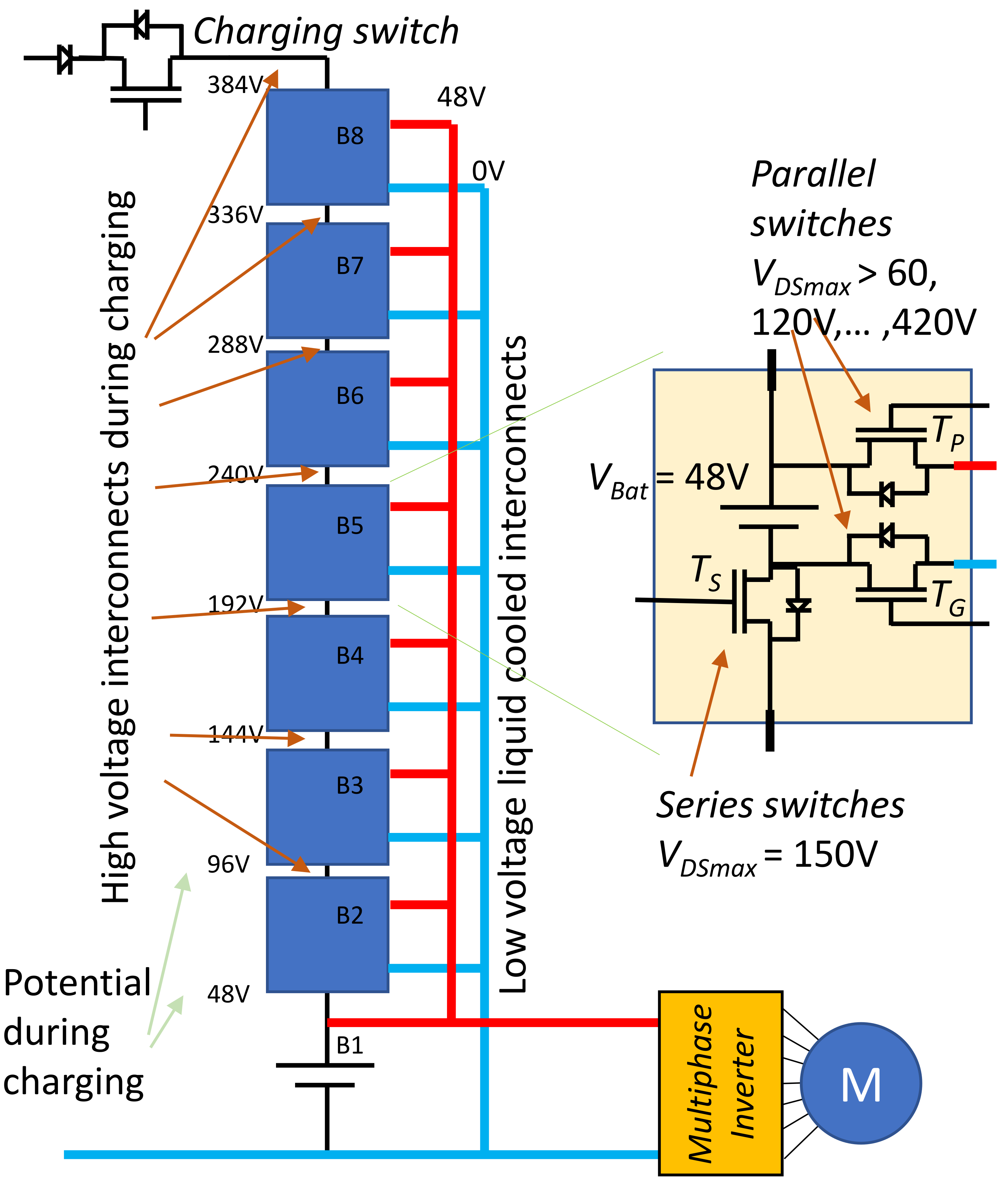
2. Battery Reconfiguration
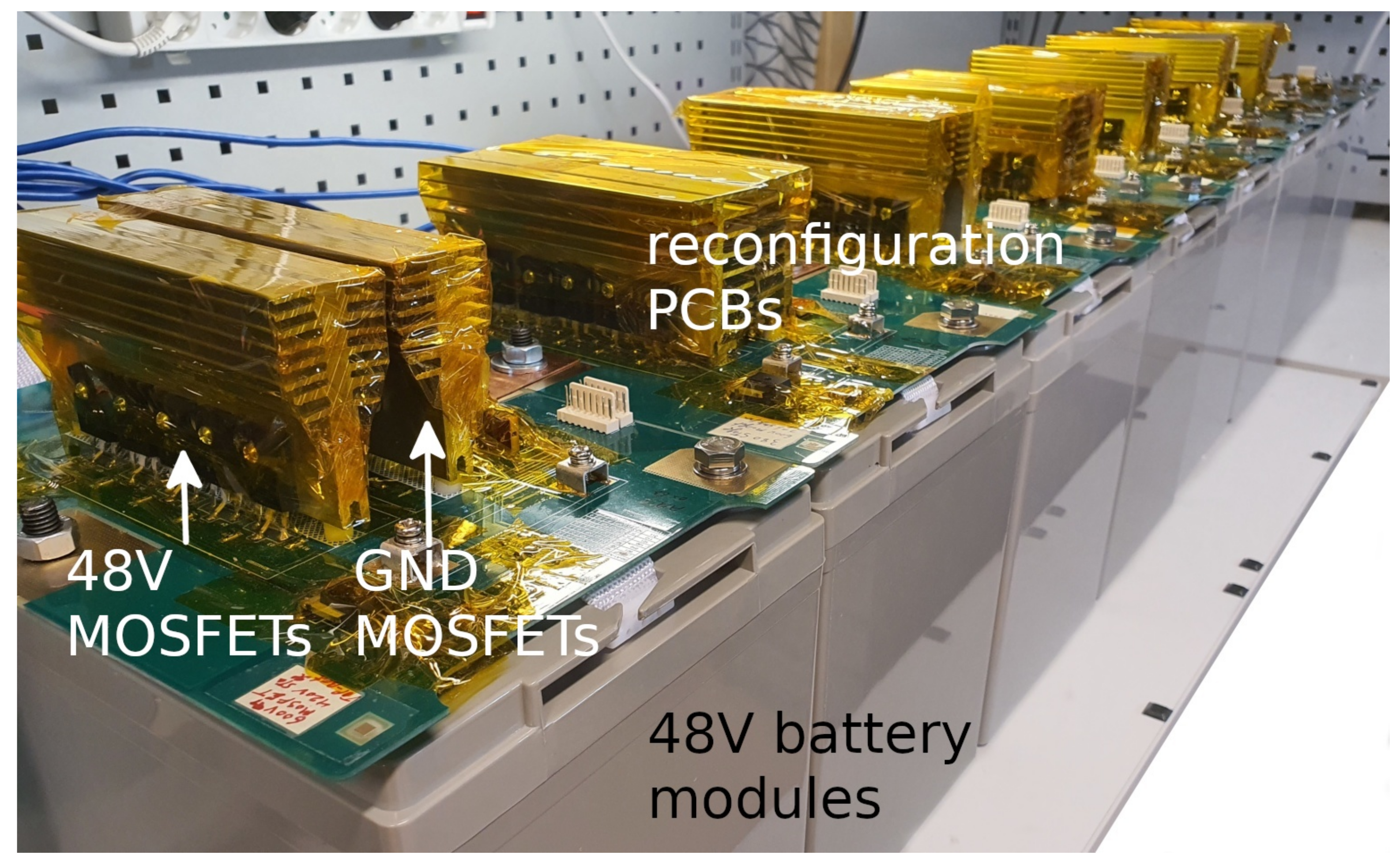
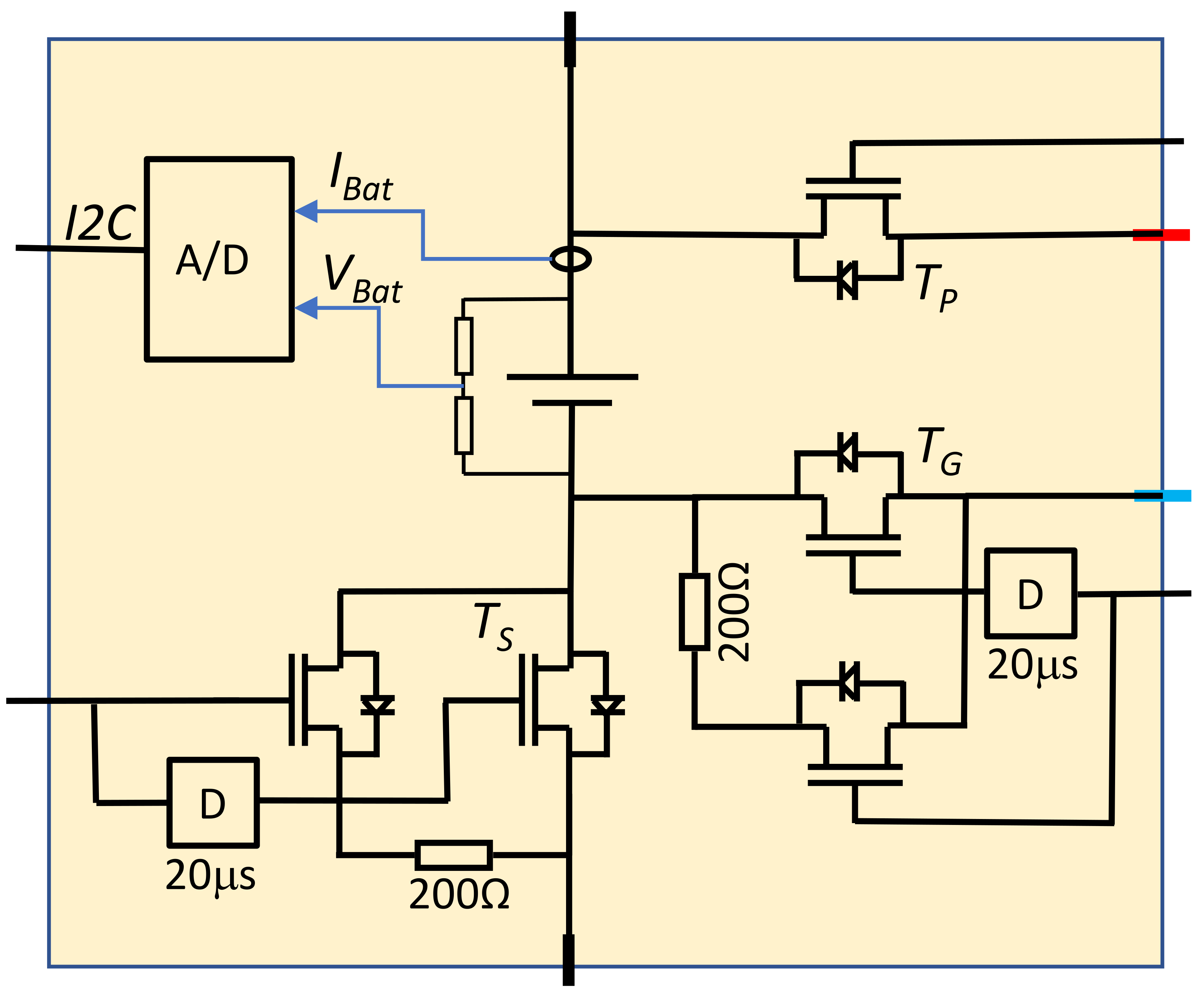
2.1. Prototype Design
2.2. Battery Pack Balancing
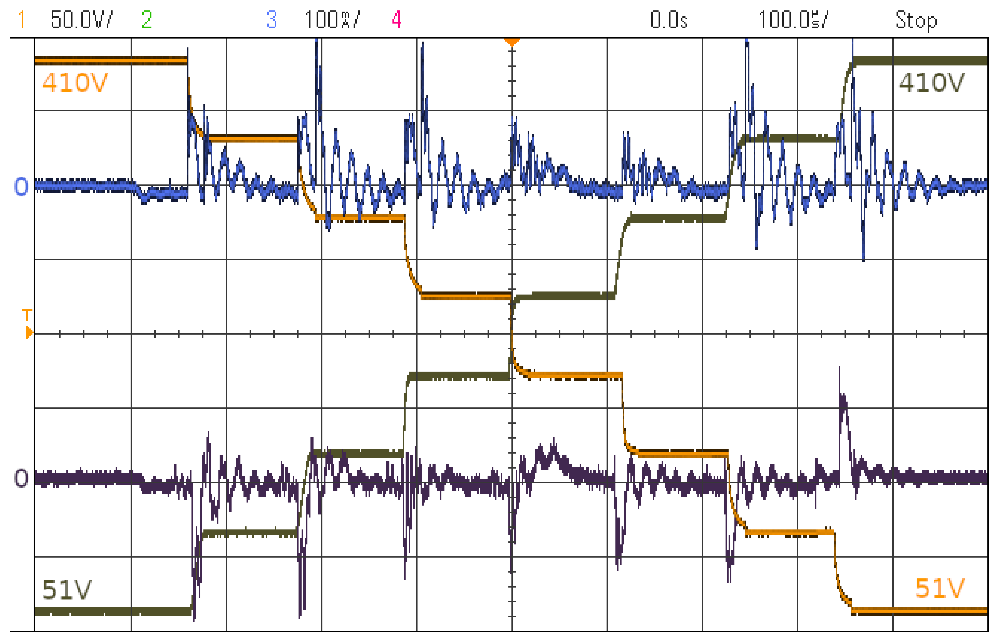
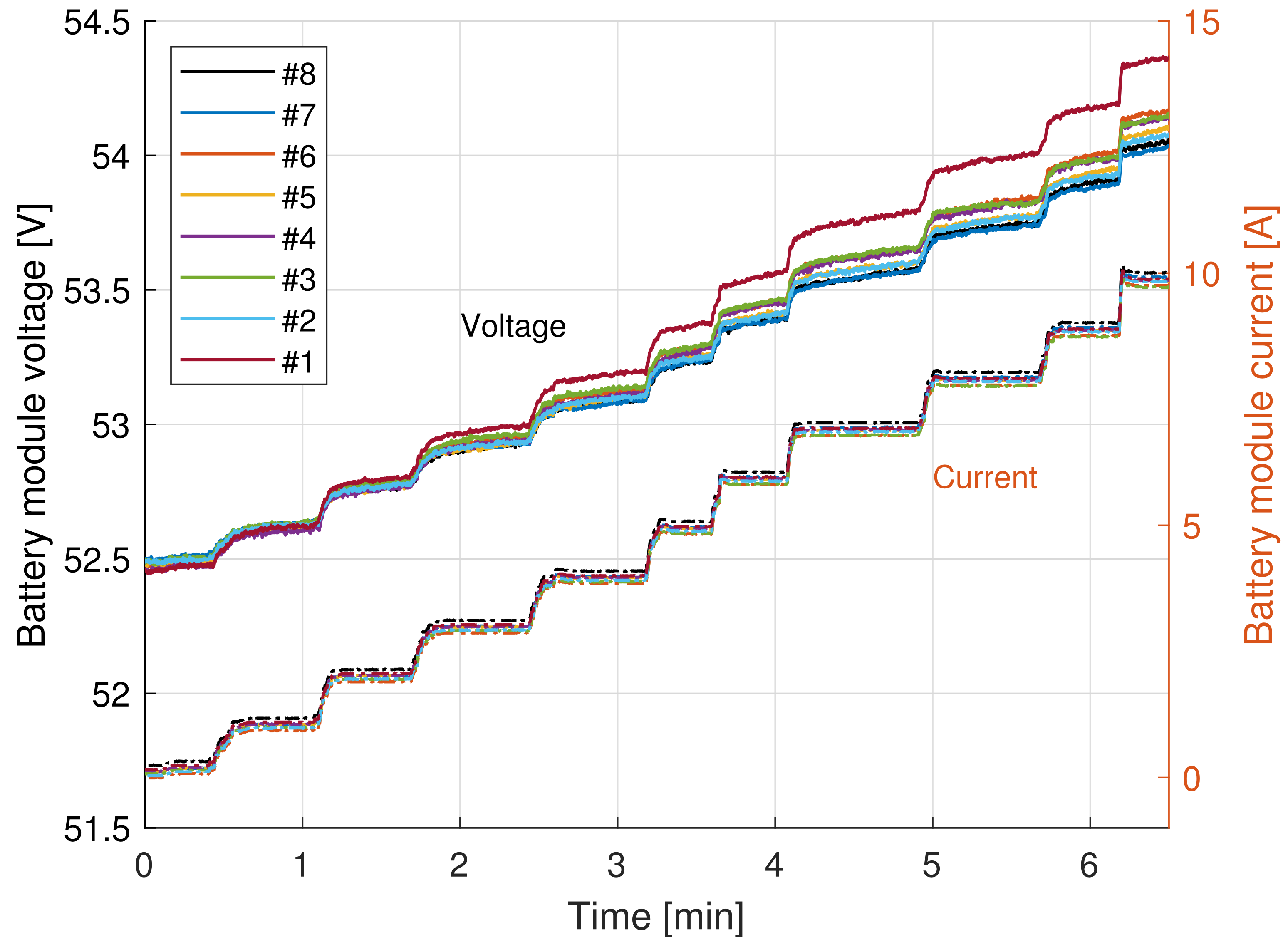
3. Experimental Results
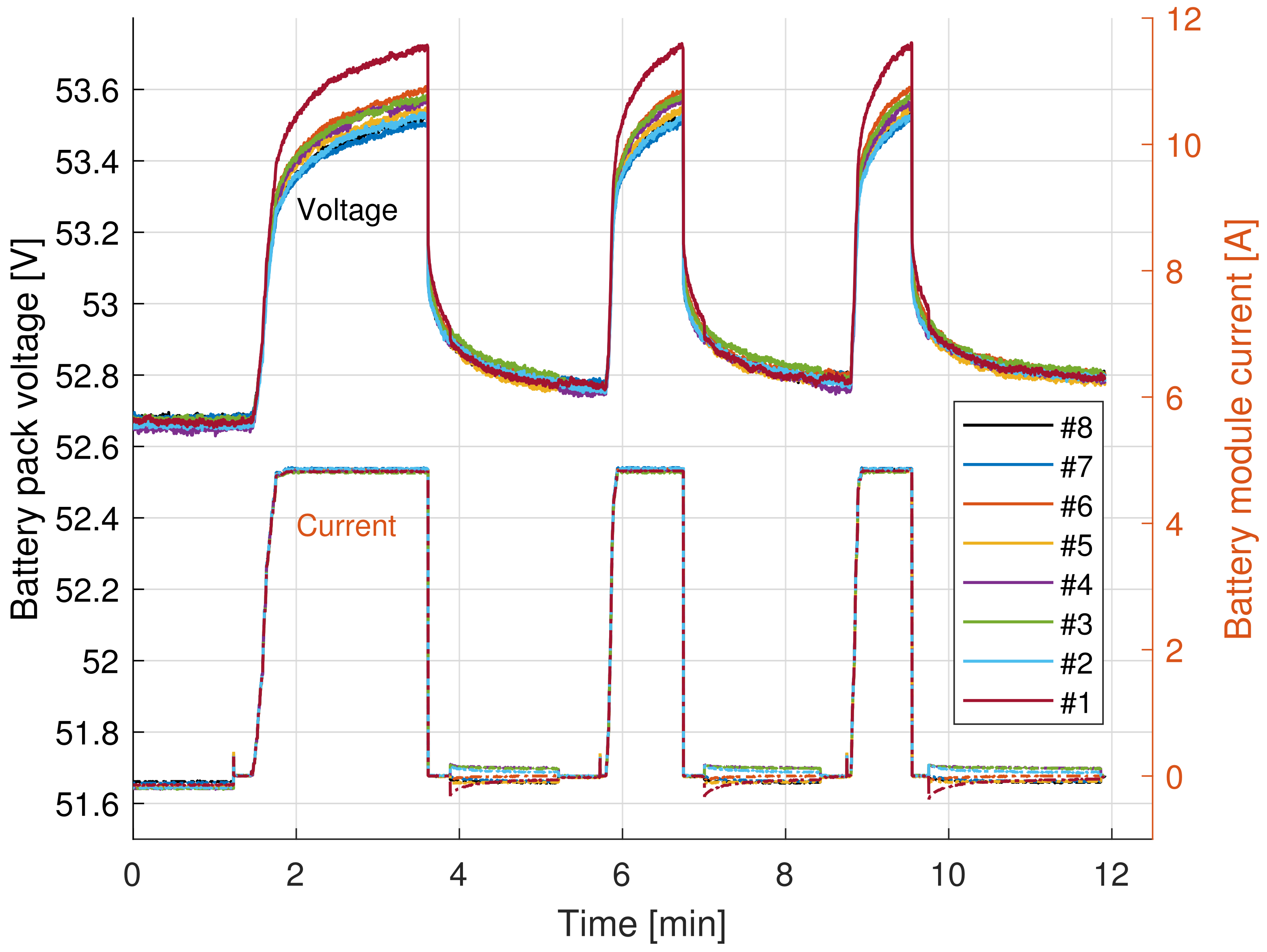
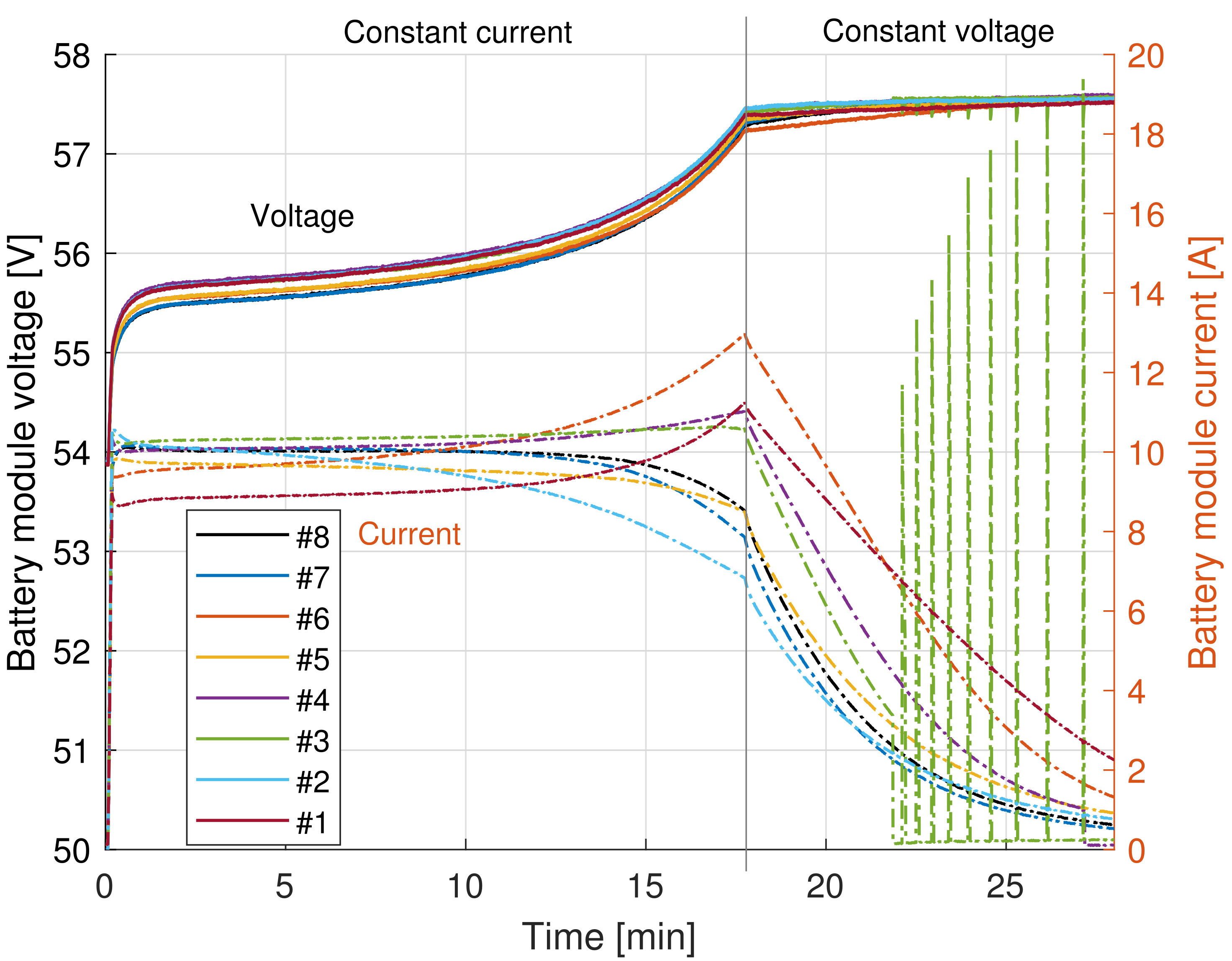
3.1. Charging
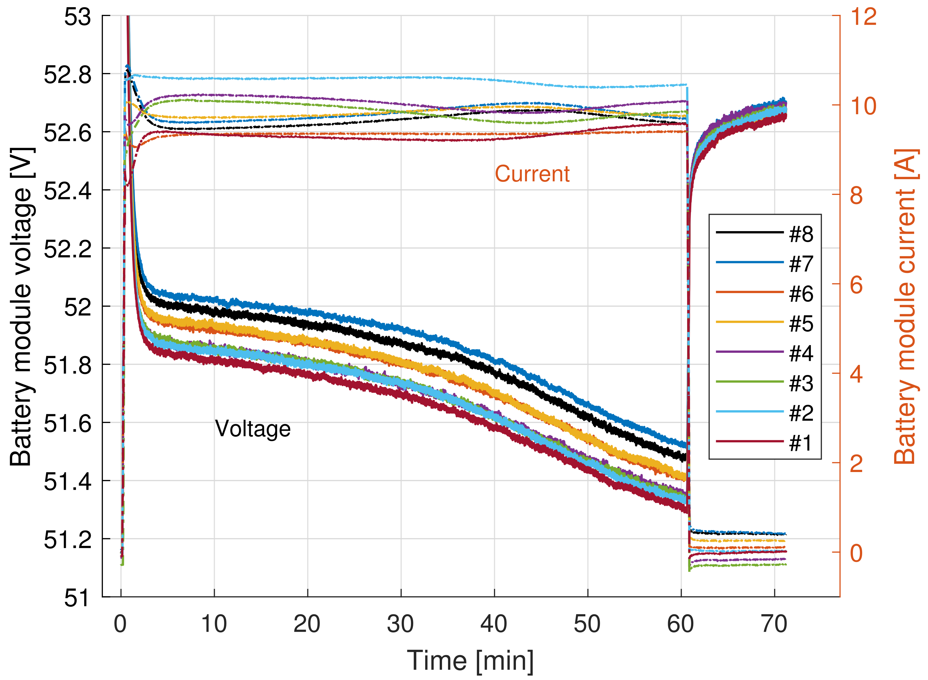
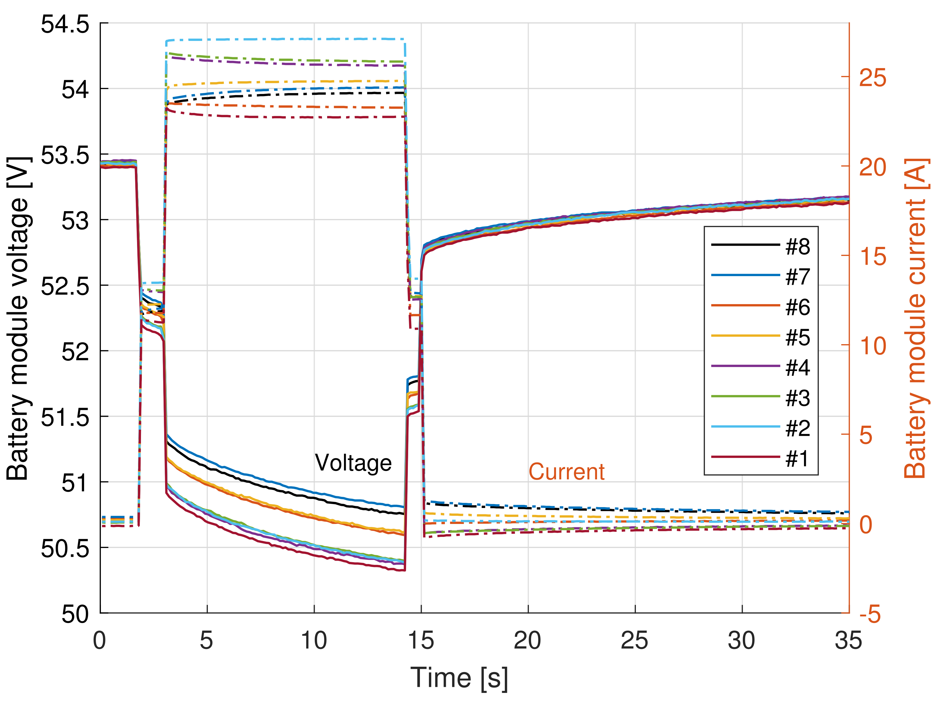
3.2. Discharging
4. System Analysis
4.1. System Performance
4.2. Cost Estimation
5. Conclusions
Author Contributions
Funding
Conflicts of Interest
References
- Bubert, A.; Oberdieck, K.; Xu, H.; De Doncker, R.W. Experimental Validation of Design Concepts for Future EV-Traction Inverters. In Proceedings of the 2018 IEEE Transportation Electrification Conference and Expo (ITEC), Long Beach, CA, USA, 13–15 June 2018; pp. 795–802. [Google Scholar] [CrossRef]
- Turska, M. High Voltage Components in Commercial Vehicles; Lapin Ammattikorkeakoulu: Rovaniemi, Finland, 2017. [Google Scholar] [CrossRef]
- Skoog, S. Component and System Design of a Mild Hybrid 48 V Powertrain for a Light Vehicle. Ph.D. Thesis, Chalmers University of Technology, Gothenburg, Sweden, 2020. [Google Scholar]
- Hayslett, S.; Van Maanen, K.; Wenzel, W.; Husain, T. The 48-V Mild Hybrid: Benefits, Motivation, and the Future Outlook. IEEE Electrif. Mag. 2020, 8, 11–17. [Google Scholar] [CrossRef]
- ICAD V50, 48 V, 50 kW High Performance Drive with Integrated Controller. Available online: https://molabo.eu/wp-content/uploads/2020/09/MOLABO_Datenblatt_ISCAD-V50-EN.pdf (accessed on 24 June 2021).
- Runde, S.; Baumgardt, A.; Moros, O.; Rubey, B.; Gerling, D. ISCAD—Design, control and car integration of a 48 volt high performance drive. Ces Trans. Electr. Mach. Syst. 2019, 3, 117–123. [Google Scholar] [CrossRef]
- Patzak, A.; Bachheibl, F.; Baumgardt, A.; Dajaku, G.; Moros, O.; Gerling, D. Driving range evaluation of a multi-phase drive for low voltage high power electric vehicles. In Proceedings of the 2015 International Conference on Sustainable Mobility Applications, Renewables and Technology (SMART), Kuwait, Kuwait, 23–25 November 2015; pp. 1–7. [Google Scholar] [CrossRef]
- Haller, S.; Persson, J.; Cheng, P.; Bertilsson, K. Multi-Phase Winding with In-Conductor Direct Cooling Capability for a 48 V Traction Drive Design. In Proceedings of the 2020 IEEE International Conference on Electrical Machines (ICEM), Online, 23–26 August 2020; Volume 1, pp. 2118–2124. [Google Scholar] [CrossRef]
- Greifelt, A.; Heiland, G.; Gerling, D. Modular 11kW bidirectional onboard charger with SiC-MOSFET technology for mobile applications. In Proceedings of the 2017 Brazilian Power Electronics Conference (COBEP), Juiz de Fora, Brazil, 19–22 November 2017; pp. 1–6. [Google Scholar] [CrossRef]
- Greifelt, A.; Rubey, B.; Gerling, D. High Temperature Superconductor Based 500 kW Smart Grid Charging for Mobile Applications. In Proceedings of the 2017 IEEE Vehicle Power and Propulsion Conference (VPPC), Belfort, France, 14–17 December 2017; pp. 1–5. [Google Scholar] [CrossRef]
- Beddingfield, R.B.; Samanta, S.; Nations, M.S.; Wong, I.; Ohodnicki, P.R.; Bhattacharya, S. Analysis and Design Considerations of a Contactless Magnetic Plug for Charging Electric Vehicles Directly from the Medium-Voltage DC Grid with Arc Flash Mitigation. IEEE J. Emerg. Sel. Top. Ind. Electron. 2020, 1, 3–13. [Google Scholar] [CrossRef]
- Han, W.; Wik, T.; Kersten, A.; Dong, G.; Zou, C. Next-Generation Battery Management Systems: Dynamic Reconfiguration. IEEE Ind. Electron. Mag. 2020, 14, 20–31. [Google Scholar] [CrossRef]
- Han, W.; Zou, C.; Zhang, L.; Ouyang, Q.; Wik, T. Near-Fastest Battery Balancing by Cell/Module Reconfiguration. IEEE Trans. Smart Grid 2019, 10, 6954–6964. [Google Scholar] [CrossRef]
- Kim, Y.; Park, S.; Wang, Y.; Xie, Q.; Chang, N.; Poncino, M.; Pedram, M. Balanced reconfiguration of storage banks in a hybrid electrical energy storage system. In Proceedings of the 2011 IEEE/ACM International Conference on Computer-Aided Design (ICCAD), San Jose, CA, USA, 7–10 November 2011; pp. 624–631. [Google Scholar] [CrossRef]
- Ci, S.; Zhang, J.; Sharif, H.; Alahmad, M. Dynamic reconfigurable multi-cell battery: A novel approach to improve battery performance. In Proceedings of the 2012 Twenty-Seventh Annual IEEE Applied Power Electronics Conference and Exposition (APEC), Orlando, FL, USA, 5–9 February 2012; pp. 439–442. [Google Scholar] [CrossRef] [Green Version]
- Kim, T.; Qiao, W.; Qu, L. Power Electronics-Enabled Self-X Multicell Batteries: A Design Toward Smart Batteries. IEEE Trans. Power Electron. 2012, 27, 4723–4733. [Google Scholar] [CrossRef]
- Lin, N.; Ci, S. Toward dynamic programming-based management in reconfigurable battery packs. In Proceedings of the 2017 IEEE Applied Power Electronics Conference and Exposition (APEC), Tampa, FL, USA, 26–30 March 2017; pp. 2136–2140. [Google Scholar] [CrossRef]
- Lithium-Ion Battery 48 V, 25 Ah, 1.28 kWh, PowerBrick+. Available online: https://www.powertechsystems.eu/home/products/48v-lithium-ion-battery-pack/25ah-48v-lithium-ion-battery-pack-powerbrick (accessed on 24 June 2021).
- Current Sensor ACS770ECB-200B-PFF-T. Allegro MicroSystems, Inc.: Manchester, NH, USA. Available online: https://www.allegromicro.com/-/media/files/datasheets/acs770-datasheet.ashx (accessed on 21 January 2022).
- Isolated Amplifier ADUM3190SRQZ. Analog Devices, Inc.: Wilmington, MA, USA. Available online: https://www.analog.com/media/en/technical-documentation/data-sheets/ADuM3190.pdf (accessed on 21 January 2022).
- 16 Bit ADC MCP3427. Microchip Technology, Inc.: Chandler, AZ, USA. Available online: https://ww1.microchip.com/downloads/en/DeviceDoc/22226a.pdf (accessed on 21 January 2022).
- Baumgardt, A.; Bachheibl, F.; Patzak, A.; Gerling, D. 48V traction: Innovative drive topology and battery. In Proceedings of the 2016 IEEE International Conference on Power Electronics, Drives and Energy Systems (PEDES), Trivandrum, India, 14–17 December 2016; pp. 1–6. [Google Scholar] [CrossRef]
- Baumgardt, A.; Bachheibl, F.; Gerling, D. 48V Traktionsbatterie—Mehr als eine Frage der Verschaltung. ATZelektronik 2016, 3, 62–69. [Google Scholar] [CrossRef]
- Power supply EA-PSB 9200-210. EA ELEKTRO-AUTOMATIK GMBH & CO. KG: Viersen, Germany. Available online: https://elektroautomatik.com/shop/media/pdf/99/6d/a1/datasheet_psb9000_en.pdf (accessed on 21 January 2022).


| Module # | Amount (, ) | [V] | [mΩ] | [mΩ] | [$] | MOSFET Type |
|---|---|---|---|---|---|---|
| 1 | none | - | - | - | - | - |
| 2 | 5,5 | 60 | 1.65 | 16.3 | IRFP7530PbF | |
| 3 | 5,5 | 200 | 7.9 | 22.8 | SUG90090E | |
| 4 | 5,5 | 200 | 7.9 | 22.8 | SUG90090E | |
| 5 | 5,5 | 300 | 35 | 20.6 | STW75NF30 | |
| 6 | 5,5 | 300 | 35 | 20.6 | STW75NF30 | |
| 7 | 5,5 | 600 | 56 | 50.6 | SiHG47N60AE | |
| 8 | 5,5 | 600 | 56 | 50.6 | SiHG47N60AE | |
| total | 80 | 204 |
Publisher’s Note: MDPI stays neutral with regard to jurisdictional claims in published maps and institutional affiliations. |
© 2022 by the authors. Licensee MDPI, Basel, Switzerland. This article is an open access article distributed under the terms and conditions of the Creative Commons Attribution (CC BY) license (https://creativecommons.org/licenses/by/4.0/).
Share and Cite
Haller, S.; Alam, M.F.; Bertilsson, K. Reconfigurable Battery for Charging 48 V EVs in High-Voltage Infrastructure. Electronics 2022, 11, 353. https://doi.org/10.3390/electronics11030353
Haller S, Alam MF, Bertilsson K. Reconfigurable Battery for Charging 48 V EVs in High-Voltage Infrastructure. Electronics. 2022; 11(3):353. https://doi.org/10.3390/electronics11030353
Chicago/Turabian StyleHaller, Stefan, Muhammad Farhan Alam, and Kent Bertilsson. 2022. "Reconfigurable Battery for Charging 48 V EVs in High-Voltage Infrastructure" Electronics 11, no. 3: 353. https://doi.org/10.3390/electronics11030353
APA StyleHaller, S., Alam, M. F., & Bertilsson, K. (2022). Reconfigurable Battery for Charging 48 V EVs in High-Voltage Infrastructure. Electronics, 11(3), 353. https://doi.org/10.3390/electronics11030353