Article

Wound Rotor Synchronous Motor as Promising Solution for Traction Applications

1
Department of Electrical Engineering, University of Management and Technology, Lahore 54770, Pakistan
2
Department of Civil Engineering, University of Management and Technology, Lahore 54770, Pakistan
3
Department of Electrical Engineering, University of Engineering and Technology, Lahore 54770, Pakistan
4
Department of Electrical and Computer Engineering, Sungkyunkwan University, Suwon 03063, Republic of Korea
5
Department of Computer Science, University of Engineering and Technology, Lahore 54770, Pakistan
6
College of Business Administration, Liwa College of Technology, Abu Dhabi P.O. Box 64141, United Arab Emirates
7
Department of Computer Science, Al Ain University, Al Ain P.O. Box 64141, United Arab Emirates
8
Department of Information Systems, College of Computer and Information Sciences, Princess Nourah Bint Abdulrahman University, Riyadh 11564, Saudi Arabia
*
Author to whom correspondence should be addressed.
Electronics 2022, 11(24), 4116; https://doi.org/10.3390/electronics11244116
Submission received: 22 October 2022 / Revised: 25 November 2022 / Accepted: 8 December 2022 / Published: 10 December 2022
(This article belongs to the Section Computer Science & Engineering)

Abstract

:
Traction applications, such as electric and hybrid vehicles, require the electrical motor to be operated at low load conditions during most of their driving cycle. Permanent magnet (PM) motors in this case may not be an optimal choice due to their poor efficiency under low load conditions despite the fact that they exhibit the best output characteristics at the rated load. However, the wound rotor synchronous motor (WRSM) demonstrates the best efficiency at low load conditions due to their controllable excitation. This paper presents an interesting comparison of WRSM and the PM motor in terms of their efficiency over the entire drive cycle of traction applications, which demonstrates that WRSMs are more suitable compared to the apparently best performance PM motor. A WRSM with similar dimensions to the 2010 Toyota Prius interior permanent synchronous motor (IPMSM) was designed and optimized in this regard. The performance comparison of the PM motor and the WRSM was presented using 2-D finite element analysis (FEA) for the WRSM and the performance analysis report of the Toyota Prius IPMSM published by the US department of energies. The FEA analysis shows that the WRSM can achieve wide torque speed characteristics. Moreover, the WRSM exhibits better efficiency under low load conditions at the higher speed or field weakening region.

1. Introduction

In today’s world, special focus is on the production of electric vehicles (EV) and hybrid electric vehicles (HEV) to extenuate the reasons of environmental pollution. High efficiency and torque density are the traits due to which permanent magnet (PM) motors are traditionally used for these applications. However, PM motors for traction applications exhibit lower efficiency at low load conditions. Additionally, the substantial increase in the cost of PM materials creates a need to find an alternative for traction applications such as EVs. Hence, many machines operating on the magnet-less principle are widely considered as another possible option.
In References [1,2], the comparative analysis of the interior permanent magnet synchronous machine (IPMSM) and induction machine (IM) is performed for the HEV application driven by IPMSM of the 2004 Toyota Prius. In Reference [3], a switched reluctance machine (SRM) is compared with the 2004 Toyota Prius machine for HEV applications. In Reference [4], a SRM is designed to achieve competitive torque and efficiency compared to the 2003 Toyota Prius IMPSM. In Reference [5], the comparison is performed between IM, IPMSM and surface mounted permanent magnet synchronous machines (SPMSM). For the fair comparison, machine dimensions, inverter size, and the vehicle specifications were kept the same. In Reference [6], the comparison between the ferrite PM-assisted synchronous reluctance machine and the IPMSM was performed for EV applications. In this research, the feasibility of replacing the IPMSM with a ferrite PM-assisted synchronous reluctance machine was investigated based on the 2004 Toyota Prius system. However, WRSMs are not yet seriously compared with the PM machines for traction application. In this paper, WRSM was designed and analyzed to show the suitability of the conventional WRSM for traction applications.
In Reference [7], a conventional WRSM was studied and analyzed to compare its performance with a PMSM. When the performance was analyzed, it was observed that PMSM cou;d be replaced as an alternative with the conventional WRSM in EV applications.
We can infer that the main trait of WRSM is that it can adjust the excitation current without drawing reactive power. With this ability, even if the voltage source of the inverter is unable to adjust the torque and power factor, WRSM can achieve this feat. This ability is not present in PM machines because the permanent magnets exhibit the properties of a constant source of excitation and their excitation cannot be controlled. For traction applications, this lack of excitation control creates problems in the design of PM machines.
The efficiency of the WRSM is marginally less than the PM machines because of the additional losses in the field winding of WRSM. Additionally, the per unit field winding resistance is only 1/4 to 1/10 than that of the resistance of phase winding of the stator, therefore, the efficiency of the two machines differs by only a few percent at rated load conditions. However, WRSM has the ability to adjust the field excitation, which allows the WRSM an added advantage in optimizing the efficiency of the WRSM above and below the rated load conditions. In addition, there are three control variables including the direct-axis current (id), quadrature-axis current (iq), and the field current (if) in WRSM, which allow more optimization possibilities compared to the PM machines, which have only two control variables; id and iq. The ability of field excitation control and flexible control with three variables makes WRSM more suitable for numerous applications, among which the most significant could be the EV applications
However, in the conventional WRSM, the excitation is provided to the field winding of the rotor for the generation of the rotor flux through the external dc supply using the brushes and slip-rings assembly. Because of this issue, the WRSM was not considered as a suitable candidate for EV applications. However, it is important to note that much research based on brushless topologies for WRSM are in progress to overcome this problem. One of the approaches to overcome this problem is to use a rotary transformer operating at high frequency [8,9,10]. Other research towards the brushless excitation is to utilize the synchronous machine as a device for self-excitation and torque production [11,12,13,14,15,16,17,18,19,20,21,22,23,24].
In Reference [11], the high winding space harmonics are utilized to excite the rotor field winding. A tooth concentrated winding is placed on the stator and the rotor, and it does not require any additional auxiliary winding for the brushless operation. In Reference [12], a PM-less synchronous machine has been studied. In this topology, space harmonics power was utilized for the field magnetization instead of permanent magnets.
In References [13,14,15,16,17,18,19], the brushless operation of WRSMs was accomplished by generating and employing the fundamental and sub-harmonic components in the MMF for the stator. For the generation of the sub-harmonic component, winding at the stator was specially arranged in these brushless topologies. In Reference [13], two parallel distributed windings with two layers were placed at the periphery of the stator and each winding was supplied using a separate three-phase inverter. In this topology, two inverters were used which is the core issue of this brushless topology, and it results in high size and cost. To overcome this issue, single-inverter fed sub-harmonically excited brushless topologies were presented in [14,15,16,17,18,19].
In References [20,21,22,23], for the brushless operation of WRSMs, a third-harmonic component was utilized in the magneto-motive force for the stator. In order to carry out brushless operations of WRSM, the third harmonic component of MMF for the stator of the spatial domain was utilized in [20]. In this brushless method, two inverters supplied the current into the open winding, which is three phase and placed on the stator. The components of the current supplied by the first and second inverter are fundamental and third harmonic, respectively. The third harmonic component of MMF induces the voltage in the harmonic winding. The rectification of the induced voltage in harmonic winding is performed, and then subsequently, the dc current is fed to the field winding of the rotor for the brushless excitation.
In Reference [21], for the excitation, the field winding of the rotor, a zero-sequence current, albeit controllable, is generated for the excitation of the rotor field winding by connecting in parallel the thyristor switches and three-phase stator winding which helps when switching during the positive as well as the negative half cycles. The voltage in the harmonic winding is induced using the third harmonic component which is produced from the zero-sequence current, and then the dc current is given to the field winding after the rectification of the said component. From these research, it is obvious that the solution towards the brushless excitation system is very promising. In the aforementioned, third-harmonically excited machines, third harmonic is generated and then utilized for the brushless operation.
In Reference [22], the why-delta configuration of the stator winding is utilized to operate the machine on a brushless principle, which was produced due to the delta coil set in the stator winding. In Reference [23], a PM-less synchronous machine was studied. In this topology, a separate inverter was used to generate the third harmonic through time-division multiplexing technique, which was later used for the brushless operation of the WRSM. All the aforementioned brushless WRSMs have the issue of a low starting torque, which makes them unsuitable for practical applications.
In this paper we present the suitability of the conventional WRSM for EV applications. Section 2 describes the WRSM design and 2-D finite element analysis (FEA) of the basic model of the WRSM. Section 3 presents the rotor pole shape optimization for the improvement of the torque and the reduction in the torque ripple for the machine. Moreover, based on the performance, the comparative analysis is performed for the optimal model of WRSM and basic model of WRSM. In Section 4, the wide speed range operation of the optimal model based WRSM is analyzed. The conclusion of this work is then presented in Section 5.

2. Machine Design Consideration and Wound Rotor Design

2.1. Machine Design Consideration

Generally, the electric vehicle applications are based on the basic WRSM model, and its layout is presented in Figure 1. There are 48 slots in the stator, and in each slot, a three-phase single layer distributed winding is placed. The configuration of stator is shown in Figure 1a. The configuration of the wound rotor with eight-pole field winding is presented in Figure 1b. For fair comparison of the conventional WRSM with the IPMSM of the Toyota Prius 2010, the outer diameter of the stator, airgap length, stator inner diameter, stack length, and shaft diameter are kept same as the IPMSM of the Toyota Prius 2010. The major machine model parameters are shown in Table 1.

2.2. Wound Rotor Design

The salient pole wound rotor of the machine was designed by keeping the outer diameter of the rotor and the shaft the same as the IPMSM of the Toyota Prius 2010. The flowchart of the design process for the salient pole rotor is given in Figure 2. The rotor field winding was designed using the constraint that the field MMF per pole ( A T f l ) for the full load was equal to m times the stator MMF per pole ( A T a ) . Where m ranges from one to two, it can be adjusted to ensure the maximum linkage between the field MMF and the stator MMF as discussed in [25,26]. Table 2 shows the design parameters of the basic model of the WRSM.

3. 2-D FEA and Rotor Pole Shape Optimization

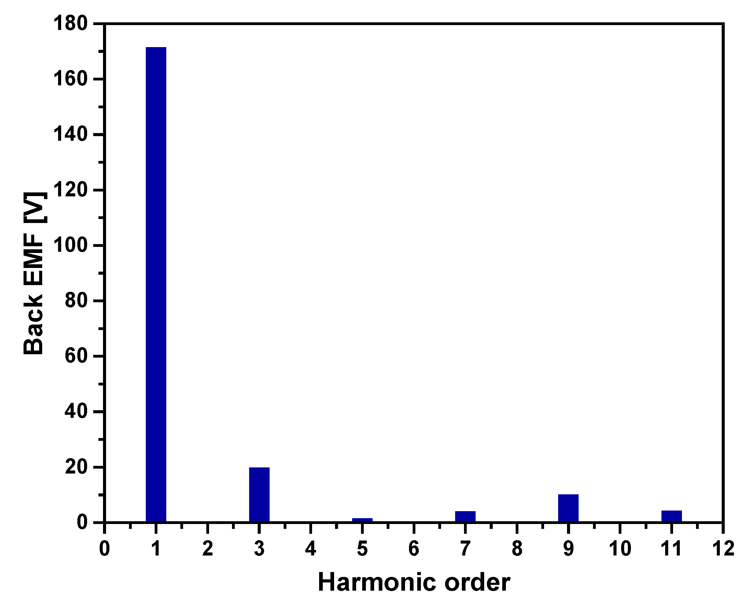
3.1. 2-D FEA of Basic Model

A 2-D FEA using Ansys Maxwell was performed on the basic WRSM model to analyze the performance of the machine. The stator winding of the machine was applied with a three-phase sinusoidal current with a value of 178.5 Arms at a 60 Hz frequency. The rotor field winding was excited by a dc current of 25 A through an external dc source.
Figure 3 represents the flux density plot of the basic model of WRSM. It depicts that the flux density at the rotor back-iron is about 1.84 T and 1.99 T at the rotor pole. The no-load back EMF of the machine at the rated speed of 2768 rpm is shown in Figure 4. The back EMF is set to the root mean squared (rms) value of 120.5 V. Moreover, the back EMF in all the phases is balanced. However, the back EMF of the basic model consists of significant value in the third and other higher-order harmonics, as shown in Figure 5. These higher-order harmonics are mainly due to the high flux density at the rotor pole and rotor back iron.
Due to the presence of these higher-order harmonics in the no-load back EMF, the basic model of the WRSM displays less output torque than the rated torque under full load conditions.
Figure 6 depicts the output torque of the basic model. The basic model of WRSM exhibits an average torque of 191.46 Nm, which is 7.5% less than the rated torque. Moreover, a ripple of 12.27% is presented in the torque of the machine. Moreover, the efficiency of the basic model at the rated speed is 85.77%. The performance of the basic model of the proposed machine is given in the Table 3. The rotor pole shape was optimized to decrease the harmonic content presented in the no-load back EMF, which results in improved torque characteristics and efficiency of the machine.

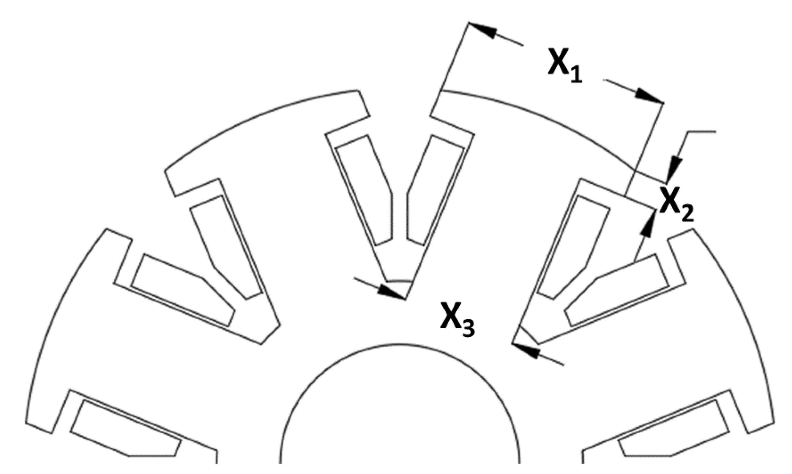
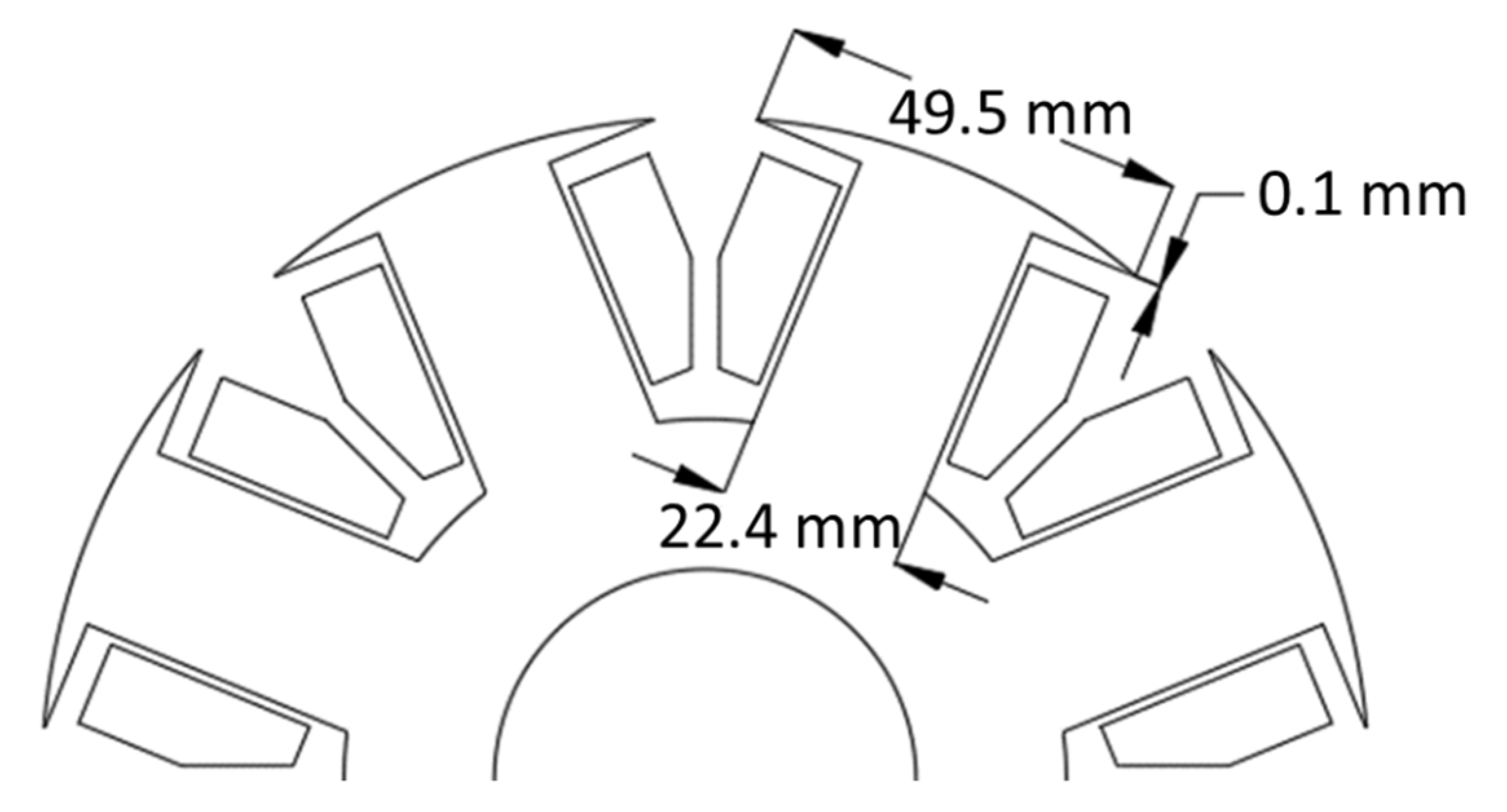
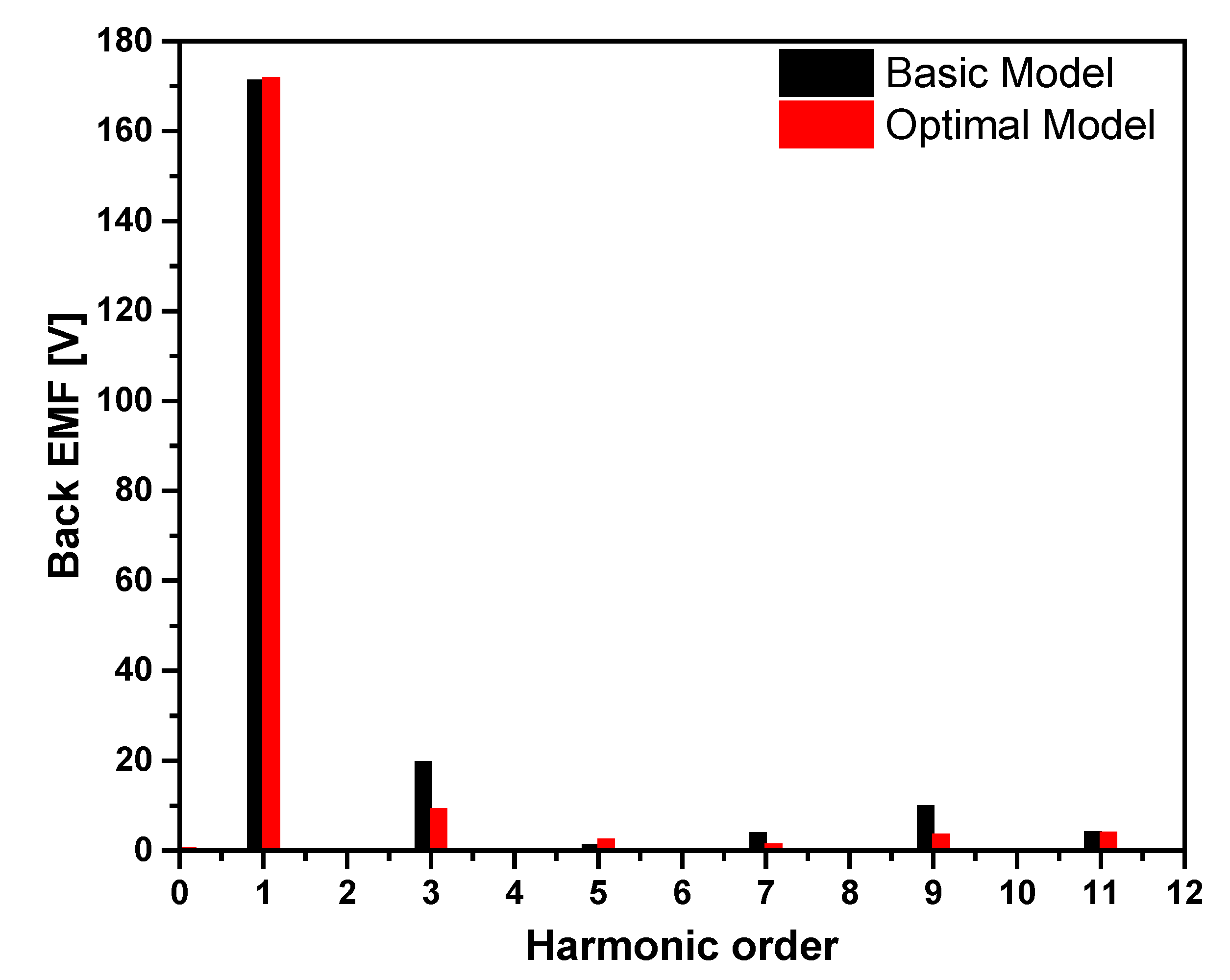
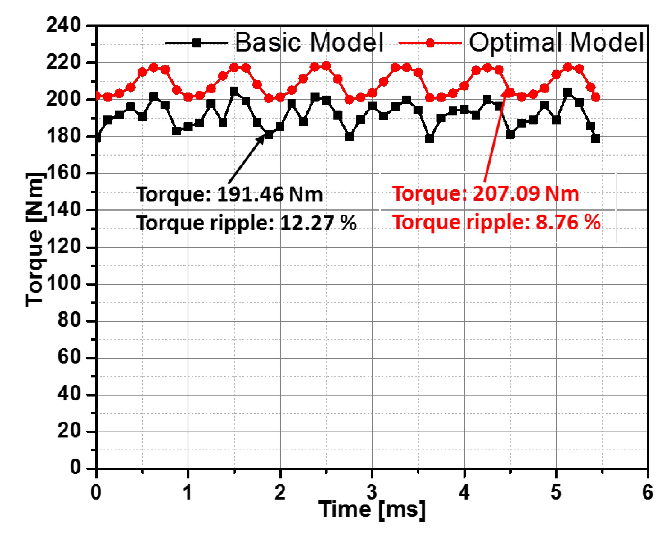
3.2. The Optimization of Rotor Pole Shape and Performance Comparison with Basic Model

The torque and torque ripple in the salient pole machine is affected by many parameters, and among them, the rotor pole shape is the most important factor. Among different design variables for the improvement of the torque performance of the machine, the pole body width (X3), the pole shoe height (X2), and the rotor pole span (X1) are considered key design variables. The pole structure of the rotor with the design variables is shown in Figure 7. Using the genetic algorithm (GA) and the Kriging method, the optimization was performed on the rotor pole shape to obtain higher torque and lower torque ripples.
Figure 8 depicts the optimal design process, where firstly, the objective functions were formed, and then the design variables and their associated ranges were decided.
  • Objectivefunctions:
Maximize the torquea and minimize the torque ripple
  • Constraint:
Efficiency > 87.77
  • Design variables:
42   mm   X 1 50   mm ,   4   mm X 2 10   mm ,   20   mm X 3 28   mm
In Equation (1), the objective functions are formulated such that the total torque is maximized, and the maximum value is greater than the torque of the basic model of WRSM. Then, the objective functions are implemented with the same weighting value for each variable of the function. Moreover, the objective function also makes sure that the torque ripple is minimized and the minimum value is less than that of the WRSM basic model. The efficiency was kept as a constraint with the maximum value greater than the basic model, as given in Equation (2). The range of design variables is given in Equation (3). Keeping in view the experiment process, the sampling points were selected after applying the Latin hypercube sampling method. The output performance of each sampling method was measured using the 2-D FEA method, and to approximate the modeling, the Kriging method was used. Then, the fitness of this model was evaluated using GA, and hence, through population analysis on PIAnO software, the optimal results were obtained. The optimal design variables are depicted in Equation (4), and the pole structure of the rotor based on the optimal model is given in Figure 9.
  • Optimized variables:
X 1 = 49.47   mm X 2 = 0.1   mm X 3 = 22.41   mm
Finally, the 2-D (FEM) was performed to check the performance of the WRSM optimal model in terms of torque. Figure 10 represents the no-load flux density of the optimal model at a rated speed. The flux density at the rotor back-iron of the optimal model decreased to about 1.6 T compared to 1.84 T in the basic model. Figure 11 shows the no-load back EMF of the WRSM optimal model in comparison to the no-load back EMF provided in the basic model. The rms value of the back EMF of the optimal model is 120 V compared to 120.5 V. However, the magnitude of the higher order harmonics in the WRSM optimal model is significantly reduced compared to the basic model, as shown in Figure 12. Due to the improvement of the shape of the back EMF and decreased flux density at the rotor back iron of the optimal model, the magnitude of the higher-order harmonics is reduced.
Figure 13 displays the torque performance of the WRSM optimal model in comparison with the basic model. The torque of the WRSM optimal model shows an improvement of 7.54% if observed in comparison with the basic model. The WRSM optimal model shows an 8.76% torque ripple which is 3.51% less than the torque ripple of the WRSM basic model. Hence, the optimal WRSM model shows a 0.97% improvement in efficiency in comparison with the basic WRSM model. Table 4 summarizes the performance comparison between the WRSM optimal and basic models.

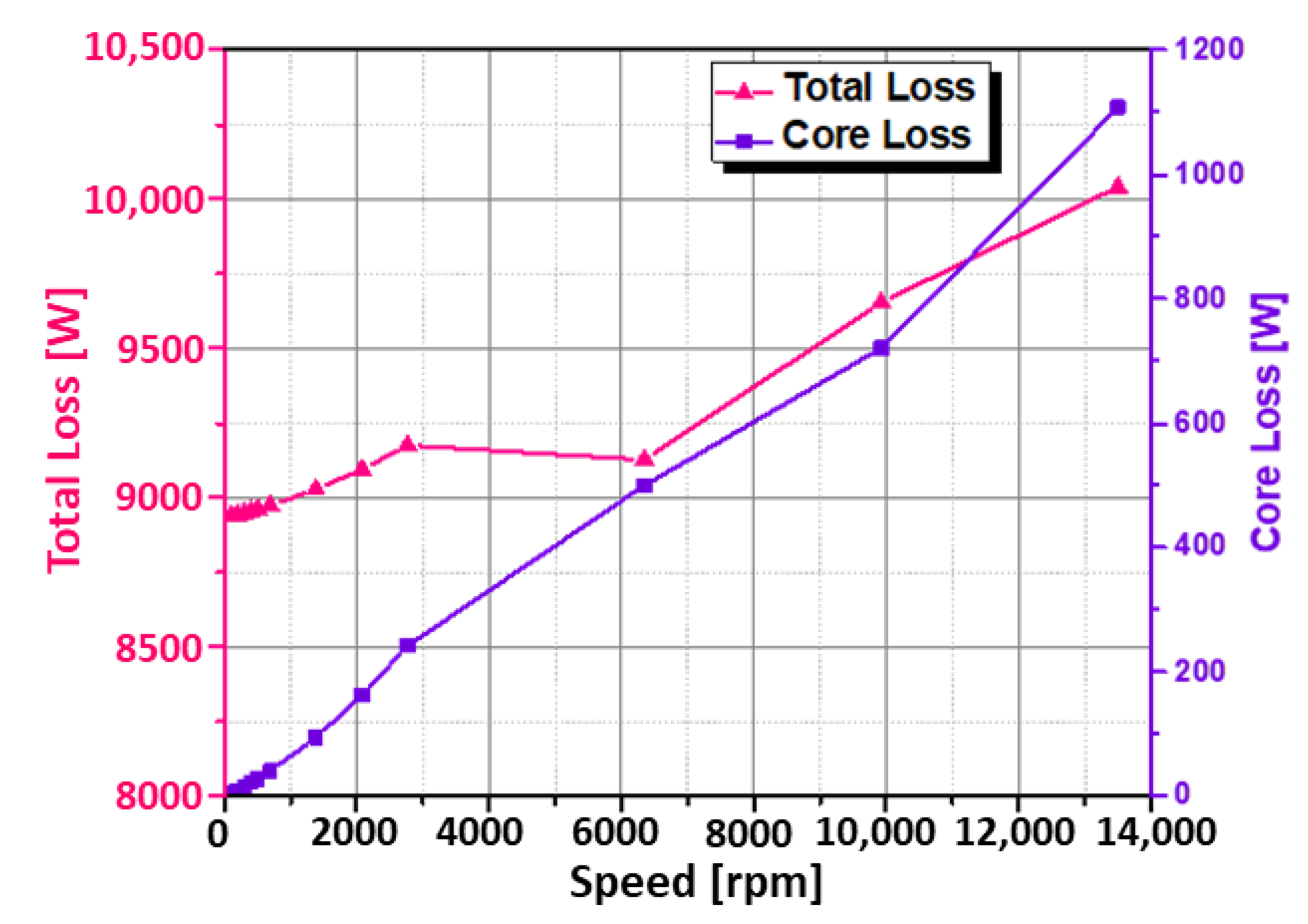
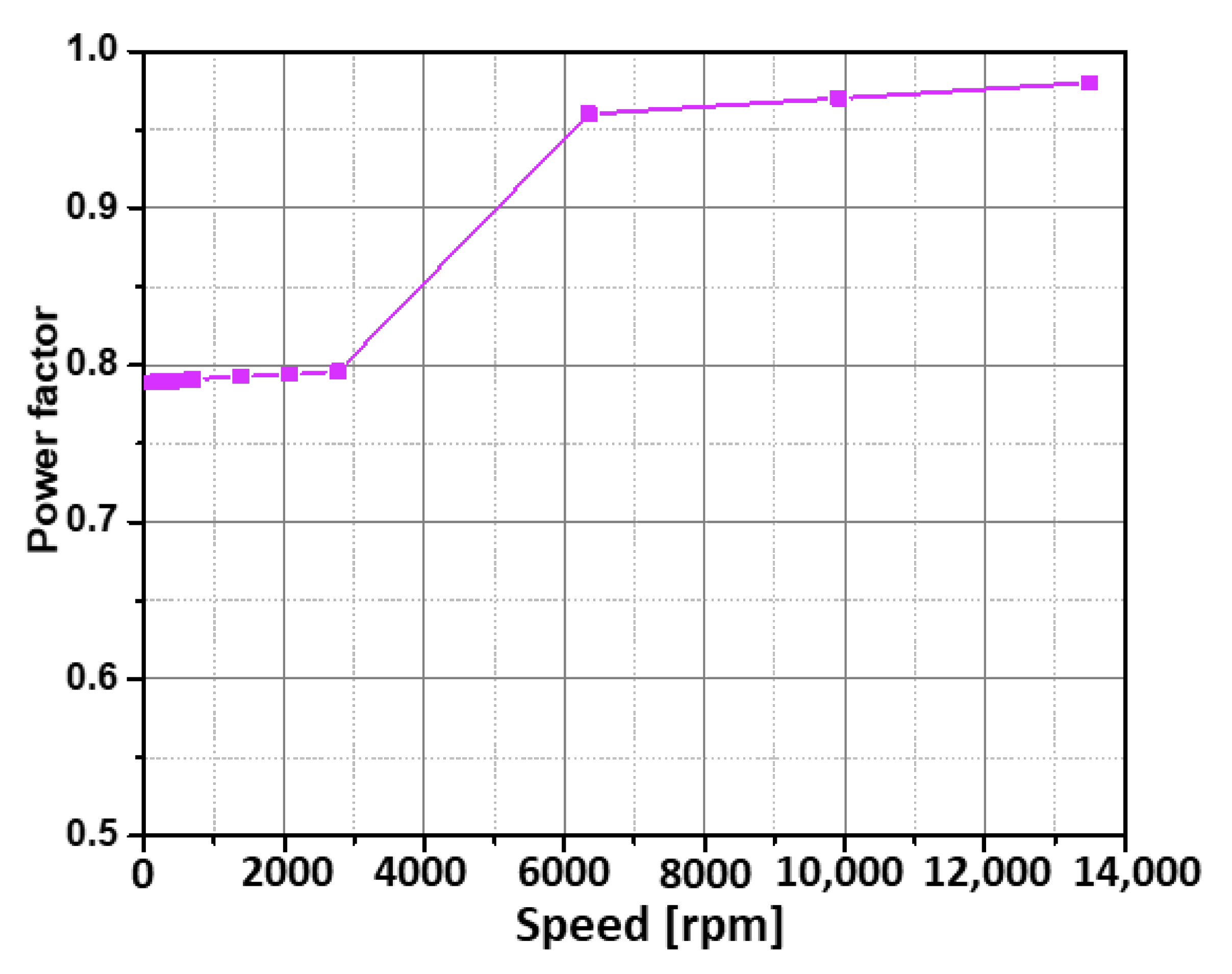
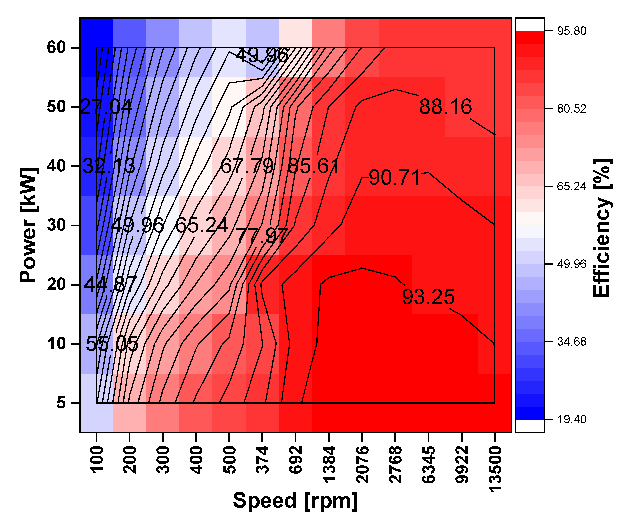
4. Wide Speed Range Operation of WRSM

Using 2D-FEA, the optimal model of WRSM was observed for a wide speed range. Firstly, the machine was analyzed to observe the performance of the machine in the constant torque and constant power region. A stator current of 178.5 Arms and a dc field current of 25 A was supplied to the rotor winding and the stator field winding, respectively. The speed of the machine was decreased from the rated speed of 2768 rpm to 100 rpm to observe the constant torque characteristics in the region of the constant torque. However, for the constant power or field weakening region, the rotor field current and the phase angle of the stator current were controlled to achieve the target wide speed range. As the speed increased above the rated speed, the phase voltages increased accordingly. The stator current phase angle was controlled to limit the voltage under the inverter limit of 230 Vrms. Figure 14 shows that the proposed WRSM can achieve the required torque and power.
Figure 15 shows the variation in the total losses, the sum of the total core, and the copper losses of the machine with the operating speed of the machine. The total losses of the machine are increased because of the increased core loss with the speed. However, the power factor of the machine is improved as the operating speed of the machine is increased. The improvement in the power factor of the machine is due to the stator current phase angle control, which suppresses the rotor flux at high speed. The variation in the power factor with the speed is shown in Figure 16. Due to the improved power factor, the efficiency of the machine showed improvement as the speed of the machine was increased from 100 rpm to the rated speed of 2768 rpm. However, above the rated speed, the efficiency of the machine is decreased by a small value due to the increase in core loss, as shown in Figure 17.
The proposed WRSM was further analyzed for the variable power speed characteristics below and above the rated speed. The machine was operated at different power ranges from 5 kW (light load) to 60 kW (rated load). The rotor and the stator field current were controlled to achieve the required power. Figure 18 shows the variation in the stator and field current variation with the change in the power of the machine. Both the currents gradually decreased with the decrease in the power of the machine. This resulted in a significant decrease in the stator and rotor copper losses of the machine. Due to this decrease in losses, the efficiency of the machine was improved above the base speed under low load conditions. However, under the base speed, the percentage decrease in the losses of the machine was less compared to the percentage decrease in the power of the machine. Due to this, the proposed WRSM exhibits low efficiency at low-speed operations. Figure 19 shows the efficiency map of the proposed WRSM for the operation of the machine with a wide range of speeds.
The comparison of the efficiency map of the machine of the proposed model with the efficiency map of the Toyota Prius 2010 IPM synchronous machine presented in [16] clearly demonstrates that the proposed machine exhibits better efficiency at high speeds under low load conditions. However, for the average load and rated load conditions, the proposed machine exhibits comparable performance to the Toyota Prius 2010 IPM synchronous machine. Due to the competitive performance of the WRSM, it should now be evident that the WRSM can be a suitable candidate for electric vehicle applications. As the occupant of the electric vehicle spends most of his/her time at the highway speed where the motor normally operates in the field weakening range, therefore, the WRSM could be favored rather than the permanent magnet motors.

5. Conclusions

In this paper, the design and performance analysis of an eight-pole, 48-slot wound rotor synchronous motor with competitive performance to the Toyota Prius 2010 IPMSM is presented for electric vehicle application. In this study, a 60-kW wound rotor synchronous motor is designed and optimized to satisfy the requirement of the Toyota Prius 2010 IPMSM. Through the 2-D FEA, it has been observed that the efficiency of the wound rotor synchronous motor is lower than the permanent magnet motor at a rated load by some percent. However, as the output power requirement decreases, the difference in the efficiency between the two machines reduces. Under a low load in both the constant torque region and field weakening region, the efficiency of the wound rotor synchronous motor is better than the permanent magnet motor. Based on this performance analysis, it is reasonable to suggest that the conventional WRSM can be a bright option to replace the permanent magnet motor in electric vehicle applications.

Author Contributions

A.H. proposed the idea, performed simulation analysis, and wrote the manuscript. Z.B. prepared the figures for the manuscript. W.T.T., U.A. and M.I. reviewed the manuscript. T.A.S., Y.Y.G. and H.K.A. reviewed the paper and provided funding for this research work. All authors have read and agreed to the published version of the manuscript.

Funding

This research received no external funding.

Conflicts of Interest

The authors declare no conflict of interest.

References

  1. Dorrell, D.G.; Knight, A.M.; Evans, L.; Popescu, M. Analysis and design techniques applied to hybrid vehicle drive machines—Assessment of alternative IPM and induction motor topologies. IEEE Trans. Ind. Electron. 2012, 59, 3690–3699. [Google Scholar] [CrossRef]
  2. Goss, J.; Popescu, M.; Staton, D. A comparison of an interior permanent magnet and copper rotor induction motor in a hybrid electric vehicle application. In Proceedings of the IEEE International Electric Machines and Drives Conference (IEMDC), Chicago, IL, USA, 12–15 May 2013; pp. 220–225. [Google Scholar]
  3. Dorrell, D.G.; Knight, A.M.; Popescu, M.; Evans, L.; Staton, D.A. Comparison of different motor design drives for hybrid electric vehicles. In Proceedings of the 2010 IEEE Energy Conversion Congress and Exposition, Atlanta, GA, USA, 12–16 September 2010; IEEE: New York, NY, USA, 2010; pp. 3352–3359. [Google Scholar]
  4. Chiba, A.; Takano, Y.; Takeno, M.; Imakawa, T.; Hoshi, N.; Takemoto, M.; Ogasawara, S. Torque density and efficiency improvements of a switched reluctance motor without rare-earth material for hybrid vehicles. IEEE Trans. Ind. Appl. 2011, 47, 1240–1246. [Google Scholar] [CrossRef]
  5. Pellegrino, G.; Vagati, A.; Boazzo, B.; Guglielmi, P. Comparison of induction and PM synchronous motor drives for EV application including design examples. IEEE Trans. Ind. Appl. 2012, 48, 2322–2332. [Google Scholar] [CrossRef] [Green Version]
  6. Cai, H.; Guan, B.; Xu, L. Low-cost ferrite PM-assisted synchronous reluctance machine for electric vehicles. IEEE Trans. Ind. Electron. 2014, 10, 5741–5748. [Google Scholar] [CrossRef]
  7. Lipo, T.A.; Du, Z.S. Synchronous motor drives-a forgotten option. In Proceedings of the 2015 Intl Aegean Conference on Electrical Machines & Power Electronics (ACEMP), 2015 Intl Conference on Optimization of Electrical & Electronic Equipment (OPTIM) & 2015 Intl Symposium on Advanced Electromechanical Motion Systems (ELECTROMOTION), Side, Turkey, 2–4 September 2015; IEEE: New York, NY, USA, 2015; pp. 1–5. [Google Scholar]
  8. Illiano, D.I.E. A separately excited synchronous motor as high efficient drive in Electric Vehicles. ATZelektron. Worldw. 2013, 8, 44–49. [Google Scholar] [CrossRef]
  9. Bortis, D.; Fässler, L.; Looser, A.; Kolar, J.W. Analysis of rotary transformer concepts for high-speed applications. In Proceedings of the 2013 Twenty-Eighth Annual IEEE Applied Power Electronics Conference and Exposition (APEC), Long Beach, CA, USA, 17–21 March 2013; IEEE: New York, NY, USA, 2013; pp. 3262–3269. [Google Scholar]
  10. Krupp, H.; Mertens, A. Rotary transformer design for brushless electrically excited synchronous machines. In Proceedings of the 2015 IEEE Vehicle Power and Propulsion Conference (VPPC), Montreal, QC, Canada, 19–22 October 2015; IEEE: New York, NY, USA, 2015; pp. 1–6. [Google Scholar]
  11. Dajaku, G.; Gerling, D. New self-excited synchronous machine with tooth concentrated winding. In Proceedings of the 3rd International Electric Drives and Production Conference (EDPC-2013), Nuremberg, Germany, 29–30 October 2013; Volume 29, p. 30. [Google Scholar]
  12. Aoyama, M.; Noguchi, T. Rare-earth free motor with field poles excited by space harmonics—Current phase-torque characteristics of self-excitation synchronous motor. In Proceedings of the 2013 International Conference on Renewable Energy Research and Applications (ICRERA), Madrid, Spain, 20–23 October 2013; IEEE: New York, NY, USA, 2013; pp. 149–154. [Google Scholar]
  13. Ali, Q.; Lipo, T.A.; Kwon, B.I. Design and analysis of a novel brushless wound rotor synchronous machine. IEEE Trans. Magn. 2015, 51, 8109804. [Google Scholar] [CrossRef]
  14. Hussain, A.; Kwon, B.I. A new brushless wound rotor synchronous machine using a special stator winding arrangement. Electr. Eng. 2018, 100, 1797–1804. [Google Scholar] [CrossRef]
  15. Hussain, A.; Atiq, S.; Kwon, B.I. Optimal design and experimental verification of wound rotor synchronous machine using subharmonic excitation for brushless operation. Energies 2018, 11, 554. [Google Scholar] [CrossRef] [Green Version]
  16. Hussain, A.; Ayub, M.; Yazdan, T.; Kwon, B. Dual Mode Dual Stator Wound Rotor Synchronous Machine for Variable Speed Applications. In Proceedings of the 2018 IEEE International Magnetics Conference (INTERMAG), Singapore, 23–27 April 2018; IEEE: New York, NY, USA, 2018; p. 1. [Google Scholar]
  17. Hussain, A.; Atiq, S.; Kwon, B.I. Consequent-pole hybrid brushless wound-rotor synchronous machine. IEEE Trans. Magn. 2018, 54, 8206205. [Google Scholar] [CrossRef]
  18. Bukhari, S.S.H.; Shah, M.A.; Rodas, J.; Bajaj, M.; Ro, J.S. Novel Sub-Harmonic-Based Self-Excited Brushless Wound Rotor Synchronous Machine Nouvelle machine synchrone à rotor bobiné sans balais auto-excitée à base de sous-harmoniques. IEEE Can. J. Electr. Comput. Eng. 2022, 45, 365–374. [Google Scholar] [CrossRef]
  19. Ayub, M.; Hussain, A.; Jawad, G.; Kwon, B.I. Brushless operation of a wound-field synchronous machine using a novel winding scheme. IEEE Trans. Magn. 2019, 55, 8201104. [Google Scholar] [CrossRef]
  20. Yao, F.; An, Q.; Gao, X.; Sun, L.; Lipo, T.A. Principle of operation and performance of a synchronous machine employing a new harmonic excitation scheme. IEEE Trans. Ind. Appl. 2015, 51, 3890–3898. [Google Scholar] [CrossRef]
  21. Jawad, G.; Ali, Q.; Lipo, T.A.; Kwon, B.I. Novel brushless wound rotor synchronous machine with zero-sequence third-harmonic field excitation. IEEE Trans. Magn. 2016, 52, 8106104. [Google Scholar] [CrossRef]
  22. Ayub, M.; Hussain, A.; Sirewal, G.J.; Kwon, B.I. Wye-delta winding configuration for brushless operation of a wound field synchronous machine. Int. J. Appl. Electromagn. Mech. 2020, 64, 1165–1172. [Google Scholar] [CrossRef]
  23. Ayub, M.; Sirewal, G.J.; Bukhari, S.S.H.; Kwon, B.I. Brushless wound rotor synchronous machine with third-harmonic field excitation. Electr. Eng. 2020, 102, 259–265. [Google Scholar] [CrossRef]
  24. Burress, T.A.; Campbell, S.L.; Coomer, C.; Ayers, C.W.; Wereszczak, A.A.; Cunningham, J.P.; Marlino, L.D.; Seiber, L.E.; Lin, H.T. Evaluation of the 2010 Toyota Prius Hybrid Synergy Drive System; (No. ORNL/TM-2010/253); Power Electronics and Electric Machinery Research Facility, Oak Ridge National Lab (ORNL): Oak Ridge, TN, USA, 2011. [Google Scholar]
  25. Lipo, T.A. Introduction to AC Machine Design; John Wiley & Sons: Hoboken, NJ, USA, 2017. [Google Scholar]
  26. Sawhney, A.K.; Chakrabarti, A. Course in Electrical Machine Design; Dhanpat Rai: Delhi, India, 2010. [Google Scholar]
Figure 1. Basic model of machine layout: (a) Single layer distributed wound stator; (b) Rotor configuration with eight-pole field winding.
Electronics 11 04116 g001
Figure 2. Salient pole wound rotor design process.
Electronics 11 04116 g002
Figure 3. No load flux density plot of basic model at rated speed.
Electronics 11 04116 g003
Figure 4. No load back EMF at rated speed.
Electronics 11 04116 g004
Figure 5. FFT plot of no-load back EMF.
Electronics 11 04116 g005
Figure 6. Output torque (basic model) at rated speed.
Electronics 11 04116 g006
Figure 7. The pole structure of the rotor and its design variables (basic model).
Electronics 11 04116 g007
Figure 8. Optimal design process.
Electronics 11 04116 g008
Figure 9. Rotor pole structure (optimal model).
Electronics 11 04116 g009
Figure 10. No load flux density plot of optimal model at rated speed.
Electronics 11 04116 g010
Figure 11. No- load back EMF comparison.
Electronics 11 04116 g011
Figure 12. FFT plot of no-load back EMF comparison.
Electronics 11 04116 g012
Figure 13. Torque comparison.
Electronics 11 04116 g013
Figure 14. Wide speed range characteristics of optimal WRSM model.
Electronics 11 04116 g014
Figure 15. Copper and core loss vs. speed.
Electronics 11 04116 g015
Figure 16. Power factor vs. speed.
Electronics 11 04116 g016
Figure 17. Efficiency vs. speed.
Electronics 11 04116 g017
Figure 18. Stator and field current variation with the change in power.
Electronics 11 04116 g018
Figure 19. Efficiency map.
Electronics 11 04116 g019
Table 1. Major machine model parameters.
ParameterUnitsValue
Power (rated)kW60
Speed (rated)rpm2768
Outer diameter (stator)mm264
Inner diameter (stator)mm161.9
Stator slots-48
No. of poles-8
Stack lengthmm50.8
Airgap lengthmm0.73
Table 2. Machine model design parameters.
Parameter UnitsValue
Rated powerkW60
Stator turns per phase-64
Stator currentArms178.5
Stator winding resistance per phase0.066
Stator current densityA/mm216.68
Rotor outer diametermm160.44
Shaft diametermm51
Field winding turns per pole-160
Field currentA25
Rotor current densityA/mm214.8
Field winding resistance4.2
Pole spanmm44.9
Shoe height for polemm5.9
Body width for polemm24.6
Body height for polemm34
Table 3. Performance of the basic model.
ParameterUnitsWRSM (Basic Model)
Back EMFVrms120.5
TorqueNm191.46
Torque ripple%12.27
Efficiency%85.77
Table 4. Basic and optimal models: performance comparison.
Parameter UnitsWRSM
(Basic Model)
WRSM
(Optimal Model)
FEAAlgorithmFEA
Back EMFVrms120.5120.4120.0
TorqueNm191.46207.2207.09
Torque ripple%12.278.758.76
Efficiency%85.7786.9086.74
Publisher’s Note: MDPI stays neutral with regard to jurisdictional claims in published maps and institutional affiliations.

