Article

Triple Coprime Vector Array for DOA and Polarization Estimation: A Perspective of Mutual Coupling Isolation

1
College of Electronic Information Engineering, Nanjing University of Aeronautics and Astronautics, Nanjing 210016, China
2
Department of Electrical and Electronic Engineering, Kyoto University, Kyoto 606-8501, Japan
*
Author to whom correspondence should be addressed.
Electronics 2022, 11(24), 4112; https://doi.org/10.3390/electronics11244112
Submission received: 24 October 2022 / Revised: 28 November 2022 / Accepted: 7 December 2022 / Published: 9 December 2022
(This article belongs to the Special Issue Sparse Array Design, Processing and Application)

Abstract

:
Traditional polarization-sensitive sensors involve a triplet of spatially collocated, orthogonally oriented, and diversely polarized electric dipoles. However, this kind of sensor has the drawback of severe mutual coupling among the three dipoles due to the characteristic of collocation, as well as low radiation efficiency because of the short length of the dipoles. Based on this problem, in this study we designed a new array structure called a ‘triple coprime array (TCA)’, equipped with long electric dipoles to obtain higher radiation efficiency. In this structure, the dipoles within different subarrays have orthogonal polarization modes, leading to mutual coupling isolation. The dipole interval of the subarrays is enlarged by means of a pairwise coprime relationship, which further weakens the mutual coupling effect and extends the array aperture. Simultaneously, a stable direction-of-arrival (DOA) and polarization estimation method is proposed. DOA information is accurately refined from the three subarrays without ambiguity problems, with the triple coprime characteristic improving the estimation results. Subsequently, polarization estimates can be obtained using the reconstructed model matrix and the least squares method. Numerous theoretical analyses were conducted and extensive simulation results verified the advantages of the TCA structure in mutual coupling, along with the superiority of the proposed joint DOA and polarization estimation algorithm in terms of estimation accuracy.

1. Introduction

Direction-of-arrival (DOA) research has been developing for several years and many studies have concentrated on the improvement of array structures and estimation algorithms [1,2,3,4]. In recent years, polarization-sensitive sensors, a kind of vector sensor, have aroused widespread interest among scholars because they can be used to detect additional polarization information from a signal, compared with the use of a scaler sensor. Joint DOA and polarization estimates can be obtained by means of a polarization-sensitive array (PSA) [5,6,7,8,9] with high accuracy, a strong anti-jamming capability, and vector signal acceptance. In [10,11], an ESPRIT-based algorithm was introduced to PSA to obtain parameter estimates, and extra pairing steps were necessary. For wideband cyclostationary signals, the classic multiple-signal classification (MUSIC) algorithm for use in polarization scenarios was proposed in [12], whereas the MUSIC algorithm presented in [13] was based on the frequency modulation signal, with both algorithms only requiring one sensor. To address the computational burden of the search process in the MUSIC algorithm, a reduced-dimensional MUSIC algorithm has been designed [14]. Through the reconstruction of the search function, polarization information is separated, and search function is only related to the DOA parameter. The sensor interval limitation is broken through from the half-wavelength at the expense of the phase ambiguity problem. However, the Poynting vector, as the identity of PSA, has been utilized in a masterly fashion [15] to obtain ambiguity-free results. In [16], a joint 2D-DOA and polarization estimation algorithm was proposed from the perspective of compress sensing.
However, the aforementioned algorithms were mainly used for PSAs, where every sensor is spatially collocated in the same position, such as a triad or six-component structure [17,18]. These kinds of sensor structure have incomplete mutual coupling isolation and are deficient in cases of inter-polarization coupling (IPC) within one sensor because the received energy will be absorbed between the orthogonal electric dipoles [19,20,21]. In addition, the length of the dipoles is assumed to be short enough to be considered as a point. In reality, the drawbacks of these short electric dipoles cannot be neglected. First, the received signals generate error because the length of the dipoles is not zero. Furthermore, another disadvantage of these short dipoles is their low radiation efficiency. This results in a decrease in the received signal strength, while the noise generated by the environment and the internal noise of the antenna have a greater deteriorating effect on the received signal. Therefore, the signal model introduced in these papers cannot be directly applied in actual engineering. Meanwhile, long electric dipoles have a larger physical size and higher radiation efficiency [22,23]. In summary, long dipoles introduce more energy-saving advantages than short ones in engineering applications, and the study of the related parameter estimation algorithms has important practical significance. However, long dipoles are not suitable for a normal array structure with a half-wavelength sensor interval because of the dense spacing. An array model with electric long dipoles has been studied recently to increase the quality of the received signal. In [22], the geometry of the electric dipole is taken into consideration in a data model, with the design of a single six-component structure. Meanwhile, a new method for joint DOA and polarization information has been proposed, without any prior knowledge of the dipoles’ electric length or the loops’ electric radius being provided. In [24], a joint DOA and polarization algorithm was proposed based on the electrically large and complete electromagnetic vector sensor. In [25], the mutual coupling influence among sensors was studied and a DOA estimation algorithm for PSAs was proposed. However, the issue of severe IPC remains unsolved. To approach this problem, the design of a spatially separated nested vector-sensor array was proposed in [26]. In this design, every position is only equipped with one dipole parallel to the x-axis, y-axis, or z-axis and IPC is completely eliminated in this way. In [27], a six-component structure was separated into six positions to obtain joint DOA and polarization estimates. In [28,29,30], the geometry of a coprime array was considered for DOA and polarization estimates. Although the abovementioned studies concentrated on IPC among dipoles or the geometry of the electric dipole, no studies have yet taken both of these points into account.
In this study, a new array structure, a triple coprime array (TCA), comprising unit-wavelength long electric dipoles, was designed and every sensor location was equipped with a dipole to eliminate IPC. The proposed TCA consists of three subarrays in which the dipoles in different subarrays have different polarization modes and are orthogonal to one another. Meanwhile, the polarization modes of the dipoles in the same subarray are the same. We assumed that the sensor intervals for the three subarrays were M λ / 2 , N λ / 2 , and O λ / 2 , respectively, and that M , N , O were coprime with one another. As a benefit of the different polarization modes, complete mutual coupling isolation among subarrays was established. Simultaneously, through the construction of the triple coprime intervals, the array aperture was significantly extended and inter-element coupling (IEC) was decreased. In addition, the TCA has a sparser structure compared with traditional coprime arrays.
With regard to the algorithm, the algorithm proposed in this paper can be used to realize the joint estimation of DOA and polarization, including the auxiliary polarization angle and polarization phase difference. First, the estimation of signal parameters via the rotational invariance techniques (ESPRIT) algorithm [9] is utilized for each subarray, obtaining a set of DOA estimation results with phase ambiguity. Then, coprime characteristic can be used to solve the ambiguity problem based on the minimum vector length principle. Since the estimation results of these three subarrays are obtained independently, the model matrices obtained corresponding to the subarrays are also ambiguous, and the overall model matrix can be recovered by rearranging its column vector. There is polarization information in the model matrix. Polarization estimates are acquired using the reconstructed model matrix and DOA estimates are acquired by means of the least squares method.
To sum up, the main contributions of this paper are as follows:
  • We have designed a new array structure called a triple coprime array (TCA), which consists of three subarrays, to enlarge the coprime array structure and reduce the mutual coupling effect. The subarrays are arranged side by side and the intervals of the sensors in different subarrays have coprime characteristics. In particular, mutual coupling isolation is established among different subarrays as a benefit of the orthogonal polarization modes of the dipoles. In addition, the sparse array structure reduces the inter-element coupling (IEC), as well as magnifying the array aperture.
  • We separated the dipoles collocated within a point into different subarrays and used long electric dipoles to improve reception efficiency. Compared with traditional PSAs, inter-polarization coupling (IPC) was eliminated but the capability of receiving vector signals was maintained. Furthermore, we used long electric dipoles of unit wavelength instead of short dipoles to improve reception efficiency, with the feasibility of the design ensured by the sparse array structure.
  • We have proposed a joint DOA and polarization estimation algorithm for TCA to deal with the problems of angle ambiguity and polarization ambiguity, in which the length of the dipoles is taken into consideration. The proposed algorithm can achieve good estimation performance because DOA estimates are calculated for the three subarrays separately. Furthermore, the coprime characteristics are employed in order to avoid the phase ambiguity problem [31]. Finally, polarization estimates were obtained via model matrix reconstruction according to the least squares method.
The rest of the paper is arranged as follows. In Section 2, we first introduce the long electric dipole array model of the proposed TCA and the data model for the signals received by the array. In Section 3, we demonstrate the advantages of the proposed TCA and verify them by means of a theoretical analysis. A joint DOA and polarization estimation algorithm for the TCA is proposed in Section 4, which exhibits low complexity and high precision. Then, simulation results are presented in Section 5. Section 6 concludes this paper.
Notations: We use lower-case (upper-case) bold characters to denote vectors (matrices). ( ) 1 represents a matrix inverse and ( ) + denotes a matrix pseudoinverse. ( ) T and ( ) H are the transpose and the conjugate transpose of a matrix or vector, respectively. ( ) T represents the conjugate of the matrix. , , denote the Kronecker product, Khatri-Rao product, and Hadamard product, respectively. diag ( ) symbolizes a diagonal matrix that uses the elements of the matrix as its diagonal elements and angle ( ) denotes a phase operator. | | | F denotes the Frobenius norm and abs ( ) represents the absolute value.

2. Data Model

Suppose that there are K far-field completely polarized signals impinging on a triple coprime array composed of three subarrays. Instead of a triad or six-component structure, all dipoles are equipped separately. As depicted in Figure 1, the sensors in the first subarray (colored in blue) are all long dipoles with a polarization direction along the y-axis (y-mode), whereas the second subarray (possessing the green dipoles) consists of dipoles which all have a polarization direction along the x-axis (x-mode). The final subarray contains the dipoles with a polarization direction along the z-axis (z-mode), which is demonstrated in red. There are P = Q 1 + Q 2 + Q 3 dipoles overall and the intervals between the adjoining dipoles of the three subarrays are d 1 = M λ / 2 , d 2 = N λ / 2 , and d 3 = O λ / 2 , respectively, where M , N , O are coprime with one another. In addition, the interval between the first and second subarrays is d 1 = M λ / 2 , whereas the interval between the second and third subarrays is d 2 = N λ / 2 .
K signals arrive at the array with the direction of θ k [ π / 2 , π / 2 ) , k = 1 , 2 , , K and their corresponding polarization information includes the auxiliary polarization angle γ k [ 0 , π / 2 ] , k = 1 , 2 , , K and the polarization phase difference η k [ π , π ) , k = 1 , 2 , , K . The received data model of the i th , ( i = 1 , 2 , 3 ) subarray is represented as follows [32]
X i = ( A i S i ρ i ) B + N i
where U i = A i S i ρ i is defined as the model matrix and A i Q i × K denotes the directional matrix of the i th subarray. Define ψ 1 ( θ ) = [ cos θ   0 ] , ψ 2 ( θ ) = [ 0   1 ] , ψ 3 ( θ ) = [ sin θ   0 ] and g ( γ , η ) = [ sin γ e j η cos γ ] T . S i symbolizes the polarization matrix corresponding to dipoles with different polarization modes and S i = [ ψ i ( θ 1 ) g ( γ 1 , η 1 ) , , ψ i ( θ K ) g ( γ K , η K ) ] . ρ i represents the radiation capability matrix, which can be expressed as follows [33]:
ρ 1 ( L , λ , θ ) = λ [ cos ( π L sin θ / λ ) cos ( π L / λ ) ] π sin ( π L / λ ) cos 2 θ
ρ 2 ( L , λ , θ ) = λ [ 1 cos ( π L / λ ) ] π sin ( π L / λ )
ρ 3 ( L , λ , θ ) = λ [ cos ( π L cos θ / λ ) cos ( π L / λ ) ] π sin ( π L / λ ) sin 2 θ
where L denotes the length of the dipoles and λ is the wavelength. B K × J represents the signal matrix, where J is the snapshot. N Q i × J is the noise matrix.
Specifically, the directional matrix can be expressed as
A i = 1 + Q i , 1 1 + Q i , 2 1 + Q i , K e j d i 2 π sin θ 1 λ + Q i , 1 e j d i 2 π sin θ 2 λ + Q i , 2 e j d i 2 π sin θ K λ + Q i , K e j ( Q i 1 ) d i 2 π sin θ 1 λ + Q i , 1 e j ( Q i 1 ) d i 2 π sin θ 2 λ + Q i , 2 e j ( Q i 1 ) d i 2 π sin θ K λ + Q i , K
where Q i , k is the y-axis offset of the i th subarray for the k th signal and Q 1 , k = 0 , Q 2 , k = e j Q 1 d 1 2 π sin θ k / λ , and Q 3 , k = e j ( Q 1 d 1 + Q 2 d 2 ) 2 π sin θ k / λ .
Merging the signals received by the three subarrays together, the signal data model on the total dipole array can be expressed as
X = X 1 X 2 X 3 ( Q 1 + Q 2 + Q 3 ) × J .

3. Triple Coprime Array Structure

In this section, the new array structure of the triple coprime array (TCA) design is elaborated in detail, with a discussion of the importance of the relatively long dipoles, the array aperture, and the mutual coupling effect. The advantages and the effectiveness of the proposed TCA are demonstrated via comparison of different array structures and through a theoretical analysis.

3.1. The Long Dipoles

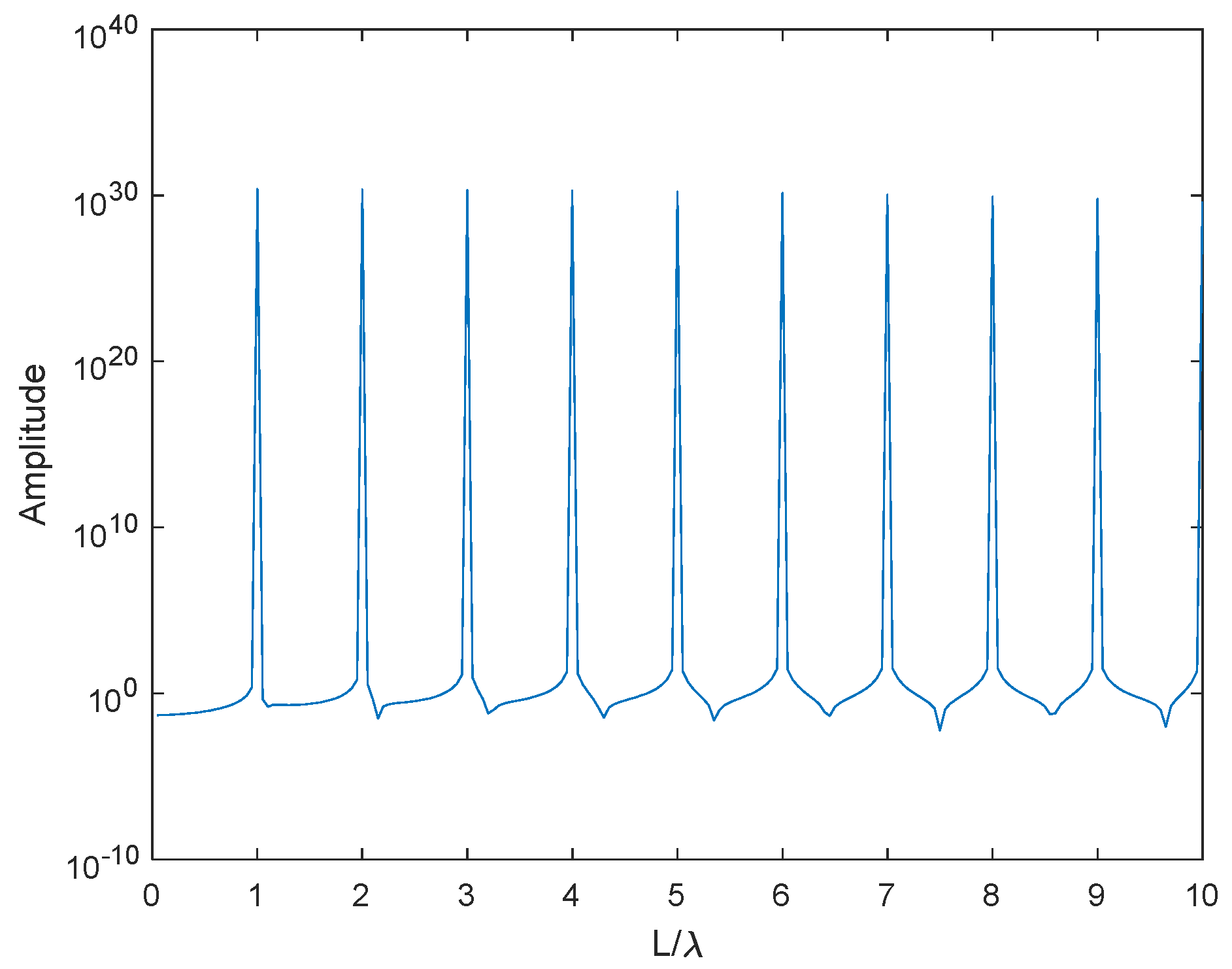
The dipoles in many proposed scaler sensor arrays, acoustic vector sensor arrays, or polarization sensitive arrays [34,35,36] consider the dipoles as a point, which means that short dipoles are equipped and the length of the dipoles is neglected. However, in reality, the radiation capability of the dipoles has a close relationship with the length of the dipoles. As depicted in Figure 2, Figure 3 and Figure 4, the radiation capability achieves its peaks when L / λ + . Of course, a current that is null at the feed point may not be zero due to nonsystematic factors in reality, but is still close to the lowest theoretical value. Simultaneously, the dipole performance increases with length and is almost periodic with respect to wavelength. It can be easily observed that when dipoles are short and viewed as a point, they do not exhibit good performance. According to the basic knowledge on microwave antennas, dipoles have an effective length, which means that the performance of a certain dipole is limited by the extent of the length because of the existence of the reverse-phase current and side lobes. This weakens the radiation effect and changes the maximum radiation direction. Therefore, the dipoles proposed in this paper are all unit-wavelength dipoles. This kind of dipole cannot adapt to a half-wavelength-spaced EVSA because the size of the sensor is greater than the sensor spacing.

3.2. Array Aperture and Mutual Coupling

According to the observations presented in the previous section, a unit-wavelength electric dipole was introduced in order to improve the radiation performance. In this case, the half-wavelength-spaced array is no longer applicable. Therefore, there is a demand for sparseness in the array structure. As a result, the proposed TCA fits well with the use of long dipoles, as well as extending the array aperture. First, compared with the triad and six-component structures [37], as demonstrated in Figure 5, the proposed TCA structure separately distributes the three dipoles from one point to different locations, which obviously extends the array aperture compared to those of the triad and six-component structures with the same dipole number. As a benefit of this separation, the inter-polarization coupling (IPC) generated by the orthogonal dipoles in a point is eliminated but the ability to receive vector signals is retained. In addition, the proposed array has sparse array spacing of over the half-wavelength. The dipole spacing of the three subarrays is M λ / 2 , N λ / 2 , and O λ / 2 , respectively, and M 2 , N 2 , and O 2 are integer coprime with one another. With the increase in the spacing, inter-element coupling (IEC) is also weakened.
Considering the mutual coupling effect, the received signal data can be defined as [38]
X i = ( C i A i S i ρ i ) B + N i
where C i , defined according to (8), is the mutual coupling matrix of the i th subarray, which only exists within one subarray because the polarization modes in different subarrays are orthogonal with one another.
C i ( p , q ) = 0 c | d p d q | | d p d q | > B λ 2   | d p d q | B λ 2
where c n = c 1 e j ( n 1 ) π / 8 / n , ( 2 n B ) and c 1 is counted as the core influencing factor, with two half-wavelength-spaced dipoles. d p , d q , 1 p , q Q i , i = 1 , 2 , 3 represent the dipole location in a certain subarray and B denotes the maximum distance of influence. The mutual coupling of a specific array structure can be estimated using a standard of coupling leakage, which is expressed as follows [38]:
Γ = | | C diag ( C ) | | F | | C | | F
If there exist I (more than one) subarrays, the total mutual coupling matrix is represented as
C = C 1 0 0 0 C 2 0 0 0 C I
In order to demonstrate intuitively the low mutual coupling performance, Table 1 summarizes the coupling leakage values obtained for some typical dense arrays and sparse arrays, in cases where B = 100 , c 1 = 0.3 e j π / 3 , and all the arrays were composed of 10 dipoles. The array apertures of the unfolded coprime array (UFCA) [39] and triple coprime array (TCA) were both 30 λ .
As is shown in the Table 1, scalar sensor arrays exhibit severe mutual coupling effects compared with vector sensor arrays due to the single polarization mode, resulting in the lack of isolation among different dipoles. On the other hand, the dipoles in the proposed TCA have three kinds of polarization modes, which are more than those of the uniform linear array (ULA) [2]. Therefore, TCA exhibits relatively low mutual coupling effects.

4. Joint DOA and Polarization Estimation Algorithm

Considering that the directional matrix contains both DOA and polarization information, the main idea of the proposed algorithm was first to measure the DOA estimates using the ESPRIT polarization algorithm [9] and afterwards to eliminate the phase ambiguity problem by means of triple coprime characteristics. Then, we aimed to reconstruct the total directional matrix with no column ambiguity and to estimate polarization by means of the least squares method.

4.1. DOA Estimation Algorithm

As is shown in (6), the received signal is divided into three parts and each part can be considered as the signal of a uniform linear subarray. The ESPRIT algorithm is applied separately to the three subarrays to obtain initial DOA estimates. First, the covariance matrices R i Q i × J , ( i = 1 , 2 , 3 ) are approximately constructed by means of J snapshots as
R i = X i X i H / J
Then, eigen-decomposition of covariance matrices is used for the signal subspace [36]:
R i = E s i D s i E s i H + E n i D n i E n i H
where i = 1 , 2 , 3 , and E s i Q i × K and E n i Q i × Q i K are the signal subspace and noise subspace of the i th subarray, respectively. D s i K × K represents the diagonal matrix containing K large eigenvalues and D n i Q i K × Q i K denotes the diagonal matrix containing the rest of the small eigenvalues.
Extracting the first Q i 1 rows and the last Q i 1 rows of E s i as E i 1 Q i 1 × K and E i 2 Q i 1 × Q i K , we can perform eigen-decomposition for E i 1 + E i 2 , finding that
E i 1 + E i 2 = T i 1 Λ i T i
where T i represents the K × K matrix with full ranks. Λ i = diag ( e j 2 π d i sin θ i , 1 / λ , , e j 2 π d i sin θ i , K / λ ) denotes the eigenvalue matrix.
In noisy environments, DOA estimates with phase ambiguity problems are measured as follows:
θ ˜ i , k = arcsin angle v i ( k ) λ 2 π d i
where v i ( k ) is the k th eigenvalue in Λ i .
Listing all the phase ambiguity estimation results calculated by the three subarrays on the axis, there exist K groups, and every group has three contiguous points because of the coprime characteristics [39]. A detailed illustration is provided in Section 5.1. Subsequently, the average values of the K groups can be calculated as the final DOA estimates, given that θ ^ k , ( θ ^ 1 < θ ^ 2 < < θ ^ K ) , k = 1 , 2 , , K .

4.2. Model Matrix Reconstruction for Polarization Estimation

Polarization information exists in the actual received signal matrix in a real scene, which can be recovered by
U ^ i = A ^ i S ^ i ρ ^ i = E s i T i 1
However, these results may suffer from column ambiguity because the ESPRIT algorithm has been employed separately for the three subarrays. We can define Γ i K × K , i = 1 , 2 , 3 as the column exchange matrices and then rearrange U ^ i to construct the total unambiguous received model matrix as
U = U ^ 1 Γ 1 U ^ 2 Γ 2 U ^ 3 Γ 3 = A 1 S 1 ρ 1 A 2 S 2 ρ 2 A 3 S 3 ρ 3
where A i , S i , ρ i , i = 1 , 2 , 3 represent the directional matrix, the polarization matrix, and the radiation capability matrix without column ambiguity, respectively. S i = [ ψ i ( θ 1 ) g ( γ 1 , η 1 ) , , ψ i ( θ K ) g ( γ K , η K ) ] . The k th column of U corresponds to the k th incident signal θ ^ k . It can be easily seen that A i , ρ i , ψ i can be reconstructed using DOA estimates. We can rewrite (16) via column division, which gives
U k = A 1 k A 2 k A 3 k ψ 1 k o M ψ 2 k o M ψ 3 k o M g k ρ 1 k o M ρ 2 k o M ρ 3 k o M = A ˜ k ψ ˜ o k g k ρ ˜ o k
where ( ) k represents the k th column ( k = 1 , 2 , , K ) of the matrix or vector and o M = [ 1 , 1 , , 1 ] T M × 1 denotes the column vector. Change the form of (17) as follows:
U k A ˜ k 1 ρ ˜ o k = ψ ˜ o k g k
which satisfies the least squares method. According to (18), g ( γ k , η k ) can be measured as
g ( γ k , η k ) = [ ( ψ ˜ o k ) H ψ ˜ o k ] 1 ( ψ ˜ o k ) H U k A ˜ k 1 ρ ˜ o k
Finally, the polarization estimates of the k th signal can be calculated as follows
γ ^ k = arctan { abs [ g ( γ k , η k ) 1 / g ( γ k , η k ) 2 ] }
η ^ k = angle [ g ( γ k , η k ) 1 ]
where g ( γ k , η k ) 1 , g ( γ k , η k ) 2 denote the 1 s t and 2 n d element of the vector, respectively.
The advantages of the proposed algorithm are embodied in the follow points. First, with regard to the DOA estimation process, compared with the phase-ambiguity-solving method of the coprime array, the method used for TCA is more stable and accurate because the actual DOA estimate is measured based on the average value of three contiguous points instead of two. Secondly, the proposed algorithm successfully solves the column ambiguity problem by rearranging the column of model matrices according to the matching of DOA estimates. As a benefit of the use of two steps, DOA and polarization estimates are paired. Finally, the least squares method is utilized for polarization estimation, in which all the information in the entire model matrix is involved in the computation process, which guarantees the good performance of the estimation results.
To sum up, the proposed DOA and polarization estimation algorithm can be divided into the following steps:
Step 1: Compute covariance matrices for three subarrays separately, according to (11).
Step 2: Perform eigen-decomposition to obtain the signal subspace E s i , i = 1 , 2 , 3 based on (12).
Step 3: Obtain coarse DOA estimates with the phase ambiguity problem (14) using the ESPRIT algorithm (13).
Step 4: Eliminate ambiguity by means of triple coprime characteristics to obtain precise final DOA estimates as θ ^ k , ( θ ^ 1 < θ ^ 2 < < θ ^ K ) , k = 1 , 2 , , K .
Step 5: Recover the received model matrix according to (15).
Step 6: Eliminate column ambiguity using column exchange matrices Γ i , i = 1 , 2 , 3 to construct the total unambiguous received model matrix as (16).
Step 7: Rewrite (16) into (17) and change its form to fit the least squares method, as in (19).
Step 8: Compute polarization estimates by means of (19), (20), and (21).
In addition, we calculated the computational complexity of the proposed algorithm to show its high efficiency. Computing the covariance matrices for the three subarrays takes O [ J ( Q 1 2 + Q 2 2 + Q 3 2 ) ] . Eigen-decomposition of the covariance matrices requires O ( Q 1 3 + Q 2 3 + Q 3 3 ) . Meanwhile, pseudoinverse, matrix multiply, and eigen-decomposition functions are required for the ESPRIT algorithm, which take O [ ( Q 1 1 ) 3 + ( Q 2 1 ) 3 + ( Q 3 1 ) 3 ] , O [ K 2 ( Q 1 + Q 2 + Q 3 3 ) ] , and O ( 3 K 3 ) , respectively. Finally, the least squares method requires O [ 8 K ( Q 1 + Q 2 + Q 3 ) + 2 K ( Q 1 + Q 2 + Q 3 ) 2 ) ] . Adding all these computational complexity values, the proposed algorithm in this paper approximately requires O [ ( 8 K + K 2 ) ( Q 1 + Q 2 + Q 3 ) + ( Q 1 1 ) 3 + ( Q 2 1 ) 3 + ( Q 3 1 ) 3 + 2 K ( Q 1 + Q 2 + Q 3 ) 2 ) + J ( Q 1 2 + Q 2 2 + Q 3 2 ) + Q 1 3 + Q 2 3 + Q 3 3 ] .
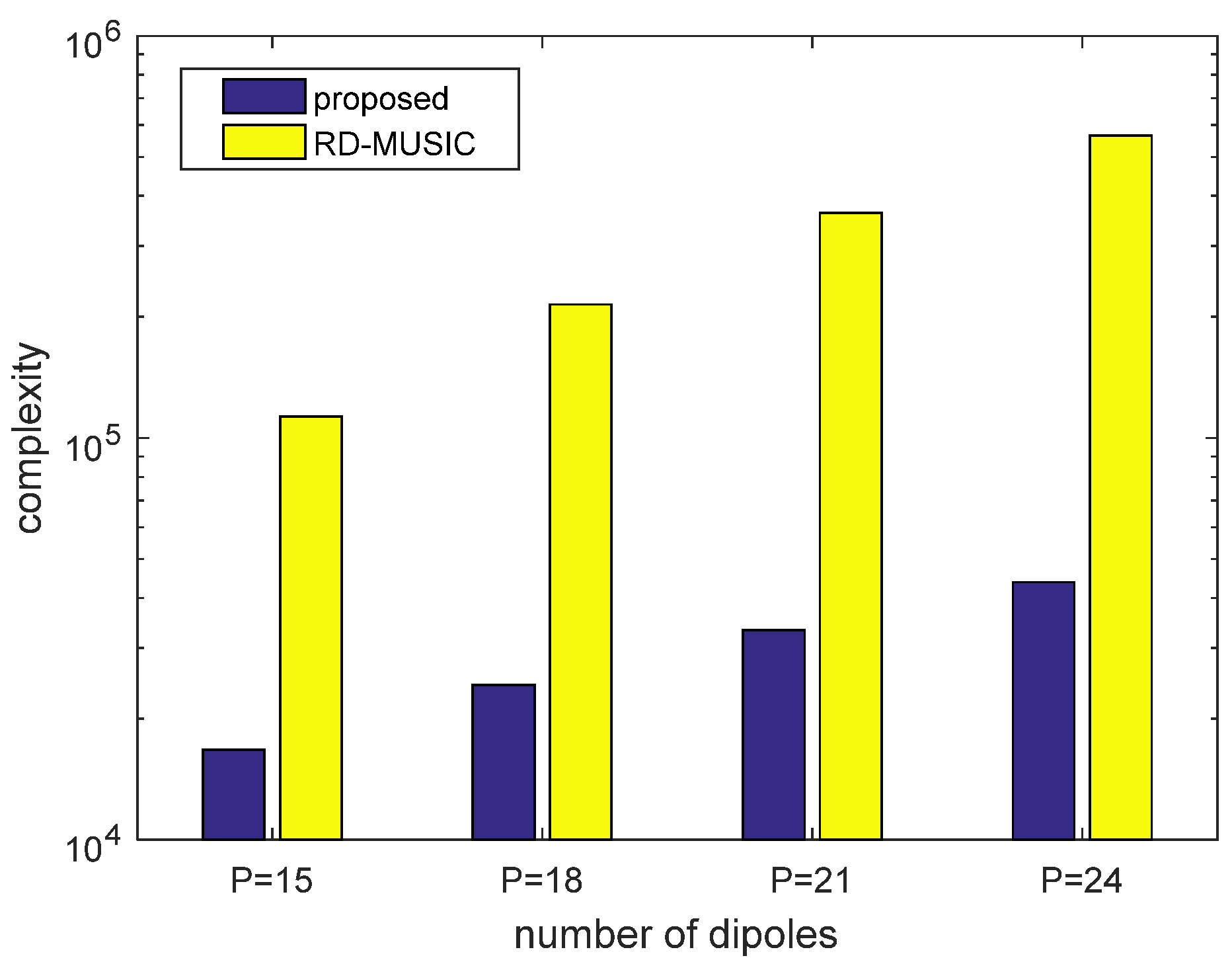
On the other hand, the reduced-dimensional MUSIC (RD-MUSIC) algorithm [36], which equips two dipoles in one location, is mainly composed of the following steps. Calculating the covariance matrix requires a complexity of O ( J P 2 ) , where P = Q 1 + Q 2 + Q 3 . Eigen-decomposition of the covariance matrix requires O ( P 3 ) . Each peak search requires the matrix multiply function, which takes O [ 4 P 2 ( P K ) ] . Assuming that there are a total of T searches for estimation, the reduced-dimensional MUSIC algorithm requires O [ 4 T P 2 ( P K ) + J P 2 + P 3 ] overall.
Suppose that there are T = 360 peak searches in the reduced-dimensional MUSIC algorithm, where J = 200 , and K = 2 . Figure 6 depicts the computational complexity of the two algorithms under different dipole numbers. The figure illustrates that the proposed algorithm can greatly reduce the calculation burden by avoiding peak searches and obtaining paired DOA and polarization estimates.

5. Simulation Results

In this section, we performed some simulations to underline the effectiveness of the proposed TCA and the corresponding algorithm, employing the root mean square error (RMSE) for the analysis of the estimation performance, which is defined as
R M S E a = 1 K k = 1 K 1 I i = 1 I a ^ k , i a k 2
where I is the count of independent Monte-Carlo simulations, a k denotes the real value of the k th DOA or polarization parameter, and a ^ k , i represents the estimated value of the k th DOA or polarization parameter in the i th simulation. In the following simulations, we supposed that two narrow-band signals impinged on the TCA with incident angles of ( θ 1 , γ 1 , η 1 ) = ( 20 , 17 , 15 ) and ( θ 2 , γ 2 , η 2 ) = ( 40 , 37 , 35 ) , and the triple coprime number was chosen as M = 5 , N = 2 , O = 3 . Furthermore, we assumed that P = Q 1 + Q 2 + Q 3 was the number of dipoles and Q 1 = Q 2 = Q 3 .

5.1. DOA and Polarization Estimation Results

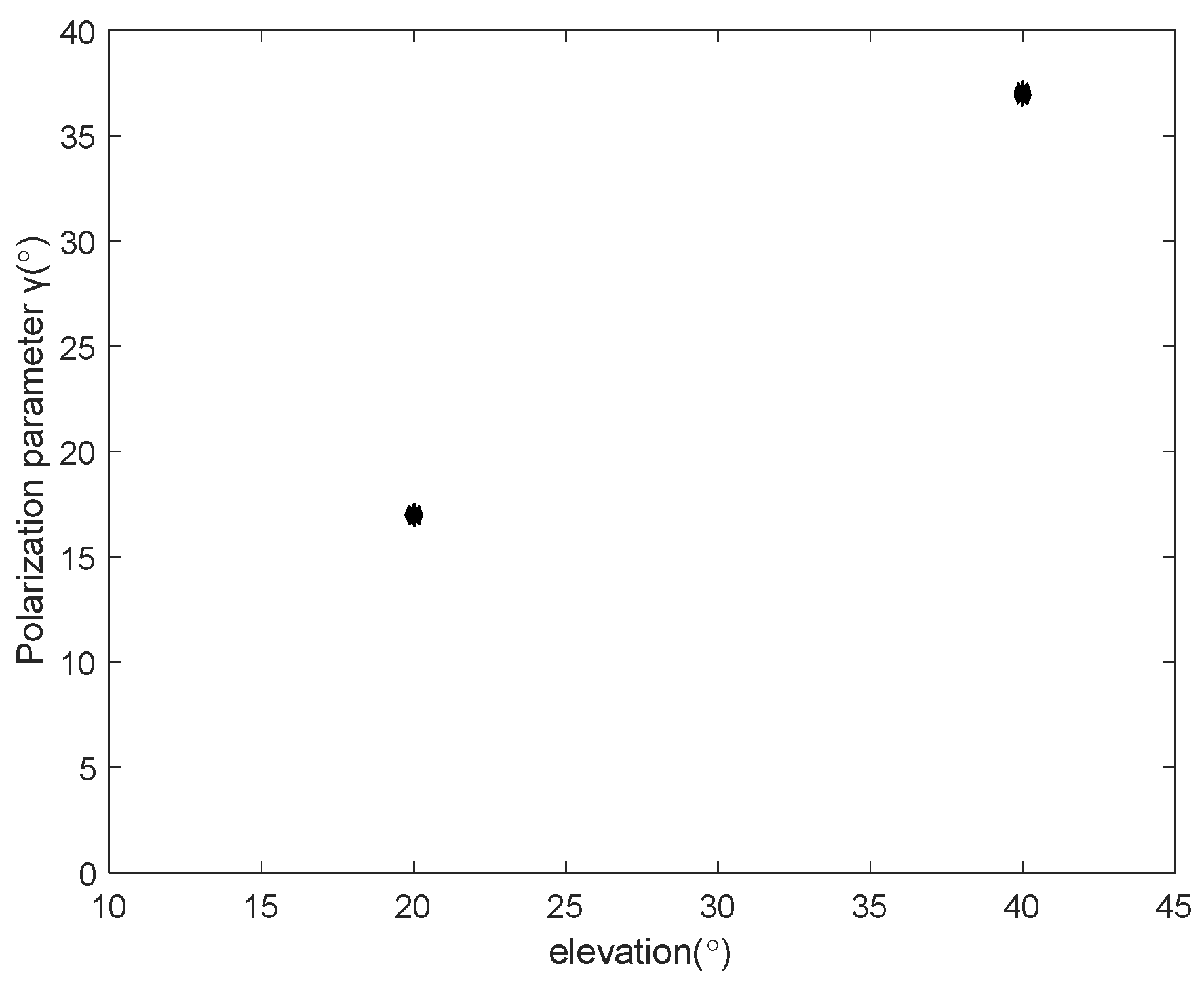
In Figure 7 and Figure 8, we present scatter plots of the DOA and polarization estimation results, where snapshots J = 200 and SNR = 20   dB . Each subarray of TCA was equipped with six unit-wavelength dipoles. As depicted in the figures, the proposed algorithm estimated the DOA and polarization parameters accurately, which corroborates the effectiveness of the proposed algorithm for TCA. In addition, the DOA and polarization estimates were well paired. This can be attributed to the phase ambiguity and column ambiguity elimination processes described in Section 4.1 and Section 4.2.
Figure 9 displays the detailed phase ambiguity elimination process introduced in in Section 4.1. It can be seen that there were three ambiguous values near sin 20 = 0.3420 and sin 40 = 0.6428 , which belonged to three subarrays. We use “+” and “*” to denote the estimates of the two DOAs, and the DOA results from the three coprime subarrays of TCA is corresponding to three kinds of color. However, the other ambiguity values were all distributed separately. Thus, the true DOA estimates can be inferred by finding the group with the nearest location to the three values among the K groups.

5.2. DOA RMSE Performance of Different Array Structures

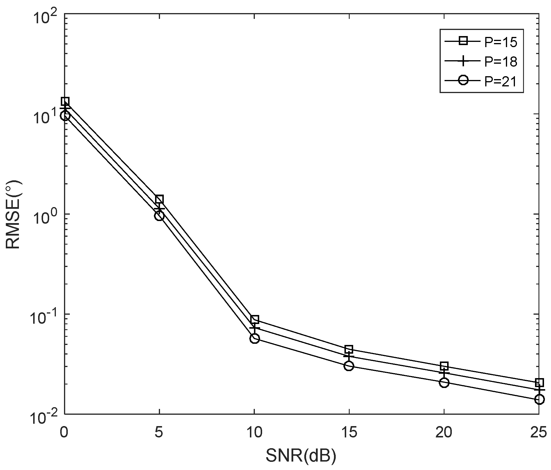
Figure 10 demonstrates the RMSE performance of different TCA configurations, where J = 200 and SNR = [ 0 , 25 ]   dB . As shown in Figure 10, the RMSE of the DOA decreased with the improvement in the SNR. Simultaneously, the parameter estimation accuracy improved with the increase in the number of dipoles due to a reinforced diversity gain.
Figure 11 illustrates RMSE comparisons of different numbers of dipoles with respect to the number of snapshots, where SNR = 10   dB and J = [ 100 , 300 ] . It can be observed in Figure 11 that RMSE decreased with the increase in the number of snapshots and dipoles. With an increase in the number of snapshots and dipoles, the covariance matrix contained more valuable information on signals, and the dipoles simultaneously received more signals, which is equivalent to an improved SNR, respectively. This resulted in more accurate parameter estimation and thus a smaller RMSE.

5.3. RMSE Performance of Different DOA Estimation Algorithms

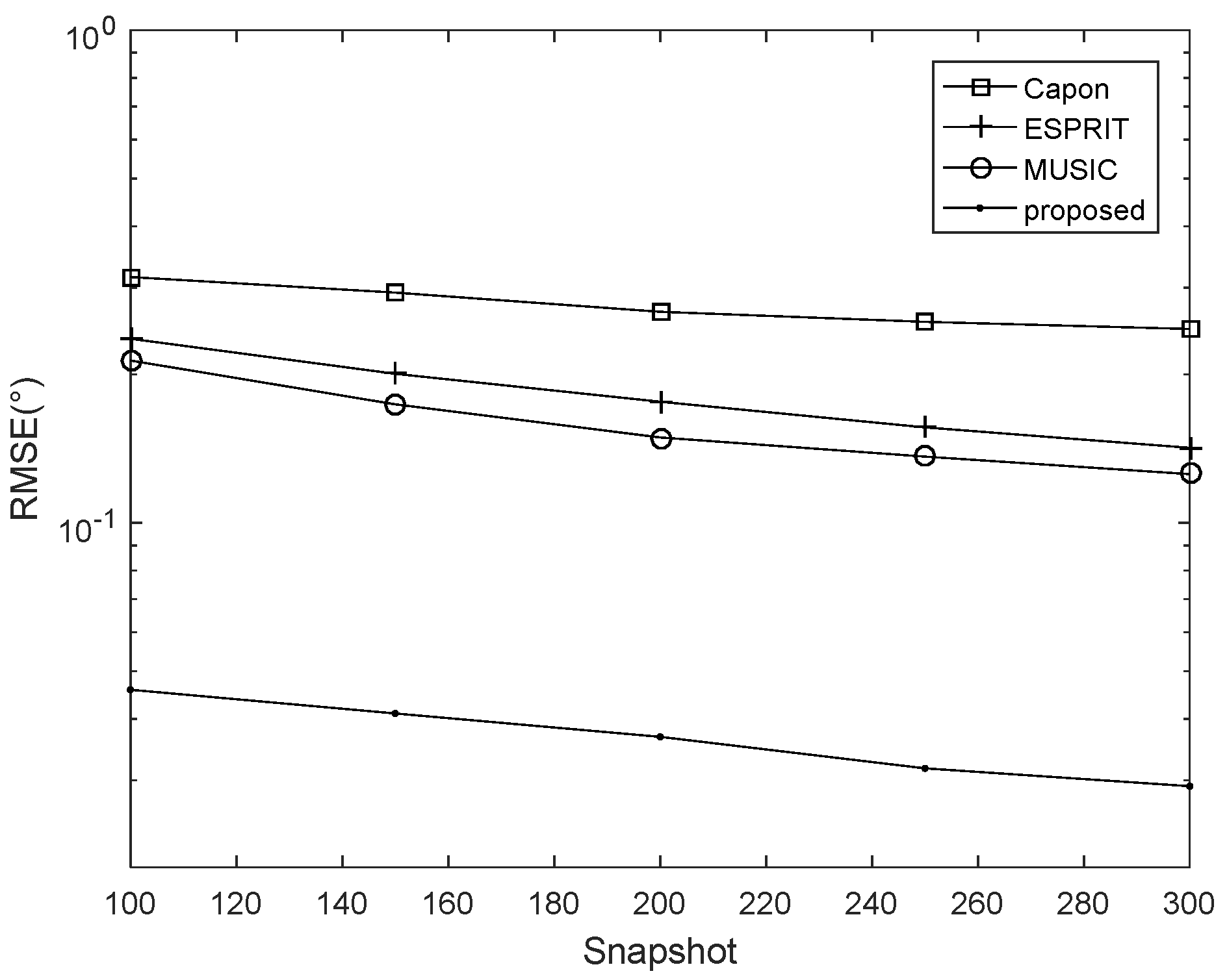
Figure 12 and Figure 13 show RMSE performance comparisons among different DOA estimation algorithms, including the proposed algorithm along with the MUSIC [36], Capon [40], and ESPRIT [9] algorithms. Each subarray of TCA was equipped with eight unit-wavelength dipoles, whereas the other algorithms were performed in four-element six-component structures. Figure 12 depicts the RMSE results versus SNR while a snapshot number of J = 300 was fixed and Figure 13 presents the RMSE results with respect to the number of snapshots while SNR = 10   dB . As revealed in Figure 12 and Figure 13, the proposed algorithm always exhibited superior performance over the other methods, as expected, due to its extended array aperture and reduced mutual coupling effects.

5.4. RMSE Performance of Different Polarization Estimation Algorithms

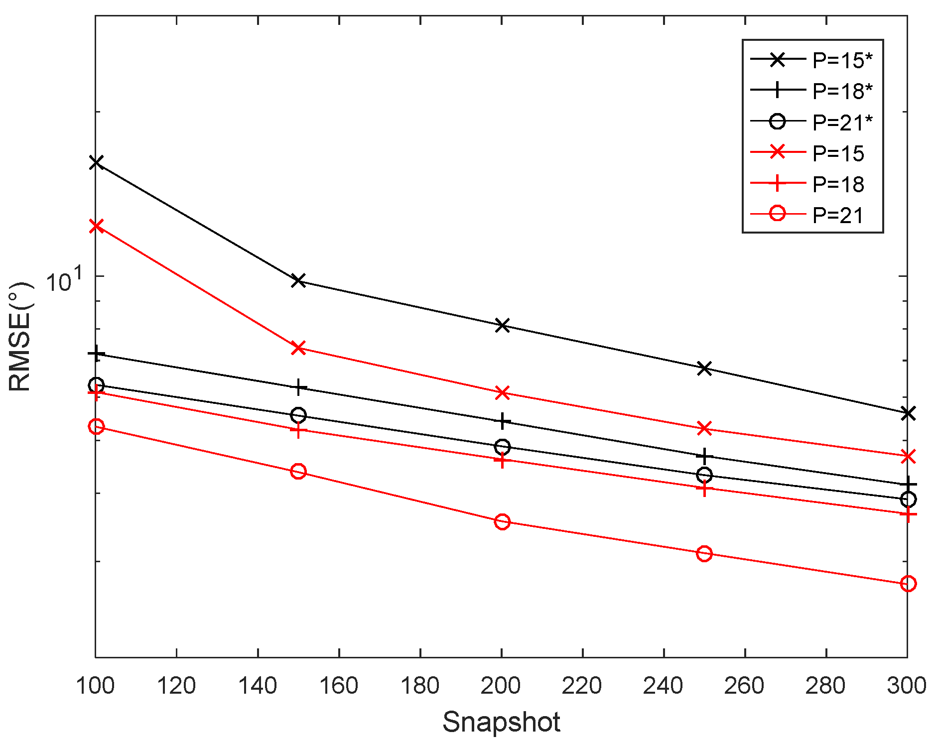
Figure 14 and Figure 15 present a polarization estimation comparison between that of the proposed algorithm and that of the algorithm in [33] versus SNR, where J = 200 , whereas Figure 16 and Figure 17 display algorithm comparisons versus the number of snapshots, where SNR = 10   dB . The RMSE of the proposed algorithm is depicted with red lines and the algorithm in [33] is represented by black lines. As shown in the figures, the proposed algorithm outperforms the algorithm presented in [33] under the same conditions.

6. Conclusions

In this study, we designed a new sparse array structure called a triple coprime array (TCA), in which electric long dipoles were used to increase the reception efficiency. Meanwhile, the problem of the array interval resulting from the use of long electric dipoles was solved by means of the sparse triple coprime structure. Moreover, the three subarrays formed a coprime array with one another, whereas the dipoles in other subarray designs have different polarization modes. This ensured mutual coupling isolation, as well as improving array performance. With respect to the parameter estimation algorithm, in this study, we proposed a joint DOA and polarization estimation algorithm, in which DOA is first obtained by using an ESPRIT-based method, and then the model matrix is reconstructed via the elimination of column ambiguity and the least squares method is utilized to acquire the polarization parameters. Our numerical results and analysis showed that the proposed TCA contributed to reducing the mutual coupling effect compared to the unfolded coprime array, and the proposed algorithm obtained better estimation precision compared to MUSIC and reduced computational complexity compared to RD-MUSIC.

Author Contributions

Conceptualization, M.Y. and Q.Y.; methodology, B.Z.; software, X.L.; validation, X.Z., X.L. and B.Z.; formal analysis, M.Y.; investigation, Q.Y.; resources, B.Z. data curation, Q.Y.; writing—original draft preparation, M.Y.; writing—review and editing, X.L.; visualization, X.Z.; supervision, M.Y.; project administration, Q.Y.; funding acquisition, X.Z. All authors have read and agreed to the published version of the manuscript.

Funding

This research was funded by China NSF Grants (61971217), Jiangsu NSF Grant (BK20200444), and Jiangsu Key Research and Development Project (BE2020101).

Conflicts of Interest

The authors declare no conflict of interest.

References

  1. Roy, R.; Kailath, T. ESPRIT-estimation of signal parameters via rotational invariance techniques. IEEE Trans. Acoust. Speech Signal Process. 1989, 37, 984–995. [Google Scholar] [CrossRef] [Green Version]
  2. Schmidt, R.O. Multiple emitter location and signal parameter estimation. IEEE Trans. Antennas Propag. 1986, 34, 276–280. [Google Scholar] [CrossRef] [Green Version]
  3. Viberg, M.; Ottersten, B.; Kailath, T. Detection and estimation in sensor arrays using weighted subspace fitting. IEEE Trans. Signal Process. 1991, 39, 2436–2449. [Google Scholar] [CrossRef]
  4. Marcos, S.; Marsal, A.; Benidir, M. Performances analysis of the propagator method for source bearing estimation. In Proceedings of the ICASSP ‘94. IEEE International Conference on Acoustics, Speech and Signal Processing, Adelaide, Australia, 19–22 April 1994; Volume 4, pp. 237–240. [Google Scholar]
  5. Hochwald, B.; Nehorai, A. Polarimetric modeling and parameter estimation with applications to remote sensing. IEEE Trans. Signal Process. 1995, 43, 1923–1935. [Google Scholar] [CrossRef]
  6. Hurtado, M.; Nehorai, A. Polarimetric Detection of Targets in Heavy Inhomogeneous Clutter. IEEE Trans. Signal Process. 2008, 56, 1349–1361. [Google Scholar] [CrossRef]
  7. Zoltowski, M.; Wong, K. Closed-form eigenstructure-based direction finding using arbitrary but identical subarrays on a sparse uniform Cartesian array grid. IEEE Trans. Signal Process. 2000, 48, 2205–2210. [Google Scholar] [CrossRef] [Green Version]
  8. Zheng, G. Two-Dimensional DOA Estimation for Polarization Sensitive Array Consisted of Spatially Spread Crossed-Dipole. IEEE Sens. J. 2018, 18, 5014–5023. [Google Scholar] [CrossRef]
  9. Gao, M.; Zhang, S.; Cao, M.; Liu, Z.; Li, M. Joint Estimation of DOA and Polarization Based on Cylindrical Conformal Array Antenna. In Proceedings of the 2020 International Conference on Virtual Reality and Intelligent Systems (ICVRIS), Zhangjiajie, China, 18–19 July 2020; pp. 1052–1056. [Google Scholar]
  10. Li, J.; Compton, R.T. Angle estimation using a polarization sensitive array. Antennas Propag. Soc. Symp. Dig. 1991, 1, 356–359. [Google Scholar]
  11. Li, J. Direction and polarization estimation using arrays with small loops and short dipoles. IEEE Trans. Antennas Propag. 1993, 41, 379–387. [Google Scholar] [CrossRef]
  12. Zhou, X.; Shi, Y.; Guo, H.; Li, J. Parameter estimation of wideband cyclostationary sources based on uni-vector-sensor. In Proceedings of the 2008 27th Chinese Control Conference, Kunming, China, 16–18 July 2008; pp. 298–302. [Google Scholar]
  13. Zhou, X.; Shi, Y.; Guo, H.; Li, J. 2-D DOA and polarization estimation of LFM signals with one electromagnetic vector sensor. In Proceedings of the 2008 9th International Conference on Signal Processing, Beijing, China, 26–29 October 2008; pp. 386–389. [Google Scholar]
  14. Wang, L.; Yang, L.; Wang, G.; Chen, Z.; Zou, M. Uni-Vector-Sensor Dimensionality Reduction MUSIC Algorithm for DOA and Polarization Estimation. Math. Probl. Eng. 2014, 2014, 682472. [Google Scholar] [CrossRef] [Green Version]
  15. Zhu, D.; Cheng, X.; Chen, B. Joint 2D-DOA and polarization estimation for Electromagnetic vector sensors array with compressive measurements. IET Radar Sonar Navig. 2022, 16, 1627–1640. [Google Scholar] [CrossRef]
  16. Zoltowski, M.; Wong, K. ESPRIT-based 2-D direction finding with a sparse uniform array of electromagnetic vector sensors. IEEE Trans. Signal Process. 2000, 48, 2195–2204. [Google Scholar] [CrossRef]
  17. Yuan, X.; Wong, K.T.; Xu, Z.; Agrawal, K. Various Compositions to Form a Triad of Collocated Dipoles/Loops, for Direction Finding and Polarization Estimation. IEEE Sens. J. 2012, 12, 1763–1771. [Google Scholar] [CrossRef]
  18. Wong, K.T.; Zoltowski, M.D. Uni-vector-sensor ESPRIT for multisource azimuth, elevation, and polarization estimation. IEEE Trans. Antennas Propag. 1997, 45, 1467–1474. [Google Scholar] [CrossRef] [Green Version]
  19. Chiu, C.-Y.; Yan, J.-B.; Murch, R.D. Compact Three-Port Orthogonally Polarized MIMO Antennas. IEEE Antennas Wirel. Propag. Lett. 2007, 6, 619–622. [Google Scholar] [CrossRef]
  20. Chiu, C.-Y.; Yan, J.-B.; Murch, R.D.; Yun, J.X.; Vaughan, R.G. Design and Implementation of a Compact 6-Port Antenna. IEEE Antennas Wirel. Propag. Lett. 2009, 8, 767–770. [Google Scholar] [CrossRef]
  21. Li, X.; Huang, X.; Nie, Z.; Zhang, Y. Equivalent Relations between Interchannel Coupling and Antenna Polarization Coupling in Polarization Diversity Systems. IEEE Trans. Antennas Propag. 2007, 55, 1709–1715. [Google Scholar] [CrossRef]
  22. Khan, S.; Wong, K.T. A Six-Component Vector Sensor Comprising Electrically Long Dipoles and Large Loops— To Simultaneously Estimate Incident Sources’ Directions-of-Arrival and Polarizations. IEEE Trans. Antennas Propag. 2020, 68, 6355–6363. [Google Scholar] [CrossRef]
  23. Arada, G.P. How Varying the Dipole Lengths of a Uniform Linear Array Affects the Performance of an ESPRIT based Direction Finding Algorithm. Int. J. Circuits Syst. Signal Process. 2020, 14, 952–958. [Google Scholar] [CrossRef]
  24. Zhu, D.; Chen, B.; Yang, M.; Dong, M. New algorithm for joint estimation of DOA and polarization based on electrically large and complete electromagnetic vector sensor. IET Radar Sonar Navig. 2020, 14, 1279–1286. [Google Scholar] [CrossRef]
  25. Svantesson, T. Modeling and estimation of mutual coupling in a uniform linear array of dipoles. In Proceedings of the 1999 IEEE International Conference on Acoustics, Speech, and Signal Processing, Phoenix, AZ, USA, 15–19 March 1999; Volume 5, pp. 2961–2964. [Google Scholar]
  26. Yang, Y.; Mao, X.; Jiang, G.; Wang, Y. Spatially Separated Nested Vector-Sensor Array with Reduced Mutual Coupling. IEEE Sens. J. 2019, 19, 5801–5817. [Google Scholar] [CrossRef]
  27. Wong, K.T.; Yuan, X. “Vector Cross-Product Direction-Finding” With an Electromagnetic Vector-Sensor of Six Orthogonally Oriented but Spatially Noncollocating Dipoles/Loops. IEEE Trans. Signal Process. 2010, 59, 160–171. [Google Scholar] [CrossRef]
  28. Shen, J.; Zhang, X.; He, Y. Blind Joint DOA and Polarization Estimation for Polarization-Sensitive Coprime Arrays Via Reduced-Dimensional Root Finding Approach. J. Circuits Syst. Comput. 2019, 29, 2050104. [Google Scholar] [CrossRef]
  29. Ahmed, T.; Zhang, X.; Zheng, W. DOA estimation for coprime EMVS arrays via minimum distance criterion based on PARAFAC analysis. IET Radar Sonar Navig. 2019, 13, 65–73. [Google Scholar] [CrossRef]
  30. Wang, X.; Huang, M.; Wan, L. Joint 2D-DOD and 2D-DOA Estimation for Coprime EMVS–MIMO Radar. Circuits Syst. Signal Process. 2021, 6, 2950–2966. [Google Scholar] [CrossRef]
  31. Zhou, C.; Shi, Z.; Gu, Y.; Shen, X. DECOM: DOA estimation with combined MUSIC for coprime array. In Proceedings of the 2013 International Conference on Wireless Communications and Signal Processing, Hangzhou, China, 24–26 October 2013; pp. 1–5. [Google Scholar]
  32. Li, B.; Bai, W.; Zhang, Q.; Zheng, G.; Bai, J.; Fu, X. High Accuracy and Unambiguous 2D-DOA Estimation With an Uniform Planar Array of “Long” Electric-Dipoles. IEEE Access 2018, 6, 40559–40568. [Google Scholar] [CrossRef]
  33. Khan, S.; Wong, K.T. Electrically Long Dipoles in a Crossed Pair for Closed-Form Estimation of an Incident Source’s Polarization. IEEE Trans. Antennas Propag. 2019, 67, 5569–5581. [Google Scholar] [CrossRef]
  34. Zhou, C.; Gu, Y.; Fan, X.; Shi, Z.; Mao, G.; Zhang, Y.D. Direction-of-Arrival Estimation for Coprime Array via Virtual Array Interpolation. IEEE Trans. Signal Process. 2018, 66, 5956–5971. [Google Scholar] [CrossRef]
  35. Li, J.; Wang, F.; Zhang, X. Two dimensional angle estimation using separate nested acoustic vector sensor array. In Proceedings of the 2017 9th International Conference on Wireless Communications and Signal Processing (WCSP), Nanjing, China, 11–13 October 2017; pp. 1–6. [Google Scholar]
  36. Zhang, X.; Chen, C.; Li, J.; Xu, D. Blind DOA and polarization estimation for polarization-sensitive array using dimension reduction MUSIC. Multidimens. Syst. Signal Process. 2012, 25, 67–82. [Google Scholar] [CrossRef]
  37. Pozar, D.M. Microwave Engineering; Wiley: Hoboken, NJ, USA, 2006. [Google Scholar]
  38. Zheng, W.; Zhang, X.; Wang, Y.; Zhou, M.; Wu, Q. Extended Coprime Array Configuration Generating Large-Scale Antenna Co-Array in Massive MIMO System. IEEE Trans. Veh. Technol. 2019, 68, 7841–7853. [Google Scholar] [CrossRef]
  39. Gong, P.; Zhang, X.; Zheng, W. Unfolded coprime L-shaped arrays for two-dimensional direction of arrival estimation. Int. J. Electron. 2018, 105, 1501–1519. [Google Scholar] [CrossRef]
  40. Stoica, P.; Händel, P.; Söderström, T. Study of Capon method for array signal processing. Circuits Syst. Signal Process. 1995, 14, 749–770. [Google Scholar] [CrossRef]
Figure 1. Data model of triple coprime array.
Electronics 11 04112 g001
Figure 2. Radiation capability (x-mode dipole).
Electronics 11 04112 g002
Figure 3. Radiation capability (y−mode dipole).
Electronics 11 04112 g003
Figure 4. Radiation capability (z−mode dipole).
Electronics 11 04112 g004
Figure 5. Structural models of the triad (a) and six-component (b) designs.
Electronics 11 04112 g005
Figure 6. Complexity comparison.
Electronics 11 04112 g006
Figure 7. Scatter plot of θ and γ .
Electronics 11 04112 g007
Figure 8. Scatter plot of γ and η .
Electronics 11 04112 g008
Figure 9. Distribution of all the ambiguity values.
Electronics 11 04112 g009
Figure 10. RMSE performance of θ versus SNR.
Electronics 11 04112 g010
Figure 11. RMSE performance of θ versus the number of snapshots.
Electronics 11 04112 g011
Figure 12. RMSE performance of different algorithms versus SNR.
Electronics 11 04112 g012
Figure 13. RMSE performance of different algorithms versus the number of snapshots.
Electronics 11 04112 g013
Figure 14. RMSE performance of γ versus SNR.
Electronics 11 04112 g014
Figure 15. RMSE performance of η versus SNR.
Electronics 11 04112 g015
Figure 16. RMSE performance of γ versus the number of snapshots.
Electronics 11 04112 g016
Figure 17. RMSE performance of η versus the number of snapshots.
Electronics 11 04112 g017
Table 1. Coupling leakage of different array structures.
Uniform Linear Array [2]Unfolded Coprime Array [39]Triple Coprime Array
Scalar array0.42950.18270.1428
Vector Array0.35690.16000.1301
Publisher’s Note: MDPI stays neutral with regard to jurisdictional claims in published maps and institutional affiliations.