Abstract
To improve the comprehensive performance of the distributed wheel-side four-wheel-drive electric bus, the problem of optimal distribution of the driving torque of the four wheel-side motors is studied. Aiming at the poor economy and failure of switching control due to the consideration of both straight and steering conditions, this paper proposes a fuzzy yaw moment control strategy based on the golden section search algorithm. Under full working conditions, according to the efficiency characteristics of the front and rear axle drive motors, the golden section search algorithm is used to determine the best front and rear axle motor torque distribution coefficient K to distribute the front and rear axle motor torques. Given the stability problems existing in the steering conditions, based on the optimal torque distribution of the front and rear axles, fuzzy control is used to calculate the expected yaw moment, and the left and right wheel torques are adjusted in real time. The simulation is carried out through TruckSim and MATLAB/Simulink, and a hardware-in-the-loop platform is built for experimentation under step steering conditions and sine wave steering conditions. The results show that the proposed torque optimal distribution strategy can optimally distribute the torque of the four drive motors through the real-time identification of working conditions. Compared with the four-wheel equal distribution, under two different steering conditions, the torque distribution efficiency of the torque distribution strategy using the golden section search algorithm increased by 4.35% and 3.83%, respectively. The energy utilization rate of the whole vehicle is improved under all of the working conditions. Under steering conditions, compared with the four-wheel equal distribution and the torque distribution strategy using the golden section search algorithm under all of the conditions, the yaw rate deviation and the slip angle deviation can be reduced, and the yaw stability has been improved.
1. Introduction
Compared with traditional vehicles, distributed drive electric vehicles (DDEVs) have the characteristics of a compact structure, high transmission efficiency, and independent control for four drive motors [1,2,3,4]. DDEVs offer the possibility of improving the handling performance and energy efficiency. Hence, DDEVs are considered the next-generation vehicles due to their flexible manipulation and emission reduction [5,6].
The driving range is a key issue that restricts the further development of electric vehicles [7,8]. Thus, DDEVs are able to use different algorithms to optimize the torque distribution in order to improve the energy utilization rate of the vehicle and to extend the driving range of electric vehicles [9,10,11]. For straight driving conditions, Chen and Wang [10] compared different methods, including the adaptive energy-efficient control allocation (EECA), the Karush–Kuhn–Tucker (KKT)-based algorithm, and the rule-based EECA. The results indicate that the KKT-based algorithm is the best in terms of improving efficiency; Wang et al. [12] used a control Lyapunov approach to develop an optimal control allocation algorithm based on a dynamic update law to generate the requested force of each actuator. However, this is impractical in real electric vehicles due to the complexity of the algorithm. Sun et al. [13] proposed a front-axle and rear-axle torque distribution method for reducing the energy consumption of the vehicle. The control logic of the in-wheel motor was obtained based on the ordinary least squares, and the algorithm of optimal torque allocation was capable of maintaining the working point of the driving motor in the high-efficiency area.
Ding et al. [14] proposed an optimal driving and braking torque vector distribution strategy based on the dynamic programming method, aiming at economy and stability, respectively. Ma et al. [15] proposed a hierarchical control method for the coordinated control of multiple control variables and the optimal torque distribution problem in military multi-wheel electric drive vehicles. The upper layer is the motion tracking control layer, which improves the coordinated control of the yaw rate and the center of mass slip angle, and the lower layer is the torque distribution control layer, which comprehensively considers the tire force and energy consumption economy, and optimizes the vehicle energy consumption economy. Based on the distributed drive electric vehicles, Zhang X. et al. [16] proposed an energy-efficient torque distribution method using an objective function that minimizes the power loss of four electric motors. Fujimoto, H. and Harada, S. [17] proposed a model-based range-extending control system for electric vehicles by optimizing the distribution of front and rear drive braking forces by considering wheel slip rates and motor losses.
When the vehicle is turning, the yaw stability is greatly reduced; when the vehicle is turning at a high speed and large wheel angle, it is prone to instability. Direct yaw moment control (DYC) is an effective way to improve the stability of DDEV [18]. In this setting, DYC judges the driver’s intention by collecting the steering wheel angle information and adjusting the yaw motion of the vehicle [19]. Katsuyama et al. [20] focused on tire slip power loss and described the development of an efficient DYC that minimizes the tire slip power loss during acceleration and deceleration while turning. Moreover, Chen et al. [21] proposed a hierarchical control strategy. The upper controller was based on the driver model and the vehicle model was designed to use sliding mode control (SMC) to calculate the required yaw moment so that the actual yaw rate can follow the required yaw rate.
In a previous work, the torque distribution strategies of DDEVs were usually exclusive for stability or economy. In this context, it is important to note that the torque distribution strategies are single and the torque distribution is not based on the current driving conditions. Hence, when the actual driving conditions are complex and changeable, the most reasonable torque distribution strategy needs to be selected according to the current driving conditions of the vehicle. Li et al. [22] comprehensively considered the steer-by-wire system and the four-wheel-drive system and suggested a coordinated control algorithm based on the vehicle dynamics and energy optimization of the driving system. Furthermore, Chen and Wang [23] proposed a hierarchical control structure based on a dynamic SMC and adaptive EECA scheme, which is used to track the driving trajectory of DDEV and to achieve optimal energy consumption. However, the switching of different control strategies between different working conditions cannot guarantee the energy utilization rate of the motor system. In theory, a switching controller with a distinguished performance is affected by the response lag of the actual electrical, mechanical, hydraulic, and information systems. Particularly, in the frequent switching process under complex and variable road conditions, the distributed drive control system may fail or even lose control.
Aiming at the problem of a poor economy and the failure of switching control due to both straight and steering conditions, this study proposes a fuzzy yaw moment control strategy based on a golden section search algorithm. Under full working conditions, according to the efficiency characteristics of the front- and rear-axle drive motors, the golden section search algorithm is used to determine the best front- and rear-axle motor torque distribution coefficient—K. K is employed to distribute the front- and rear-axle motor torques that can achieve the best economy of the vehicle. Given the existing stability problems in the steering conditions and based on the optimal torque distribution of the front and rear axles, fuzzy control is used to calculate the expected yaw moment. The left and right motor torques are adjusted in real-time according to the expected yaw moment.
TruckSim and MATLAB/Simulink are used for software-in-the-loop (SIL) simulation. Furthermore, DSP development board and PXI chassis are used to build a hardware-in-the-loop (HIL) platform for test verification. The test results show that the proposed control strategy not only improves the economy of the vehicle, but it also improves the yaw stability, the control effect is outstanding, and it has good theoretical significance and engineering value.
2. DDEV Model
Figure 1 shows the configuration of the DDEV. In this paper, the distributed drive electric bus is equipped with four wheel motors, and the four-wheel-independent control is realized through different signals of the controller. The vehicle controller calculates the corresponding driving torque according to the torque distribution strategies. Motor controllers transmit it to the driving wheels through the wheel motors and reducers to drive the electric bus. The related parameters of the distributed drive electric bus are shown in Table 1.
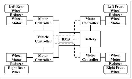
Figure 1.
Configuration of DDEV using wheel motors.

Table 1.
Electric bus parameters.
When the same type of motors are used for the front-rear axle, the even distribution can optimize the overall efficiency of the entire vehicle [24]. In this paper, different types of drive motors are used for the front and rear axles of the electric bus. The two coaxial left and right motors have the same type of system configuration. The specific parameters of the front and rear axis motors are presented in Table 2.
Table 2.
Motor parameters of the front and rear axles.
3. DDEV Torque Distribution Strategy
Given the existing instability problems in the steering conditions, the torque distribution strategy used fuzzy control to calculate the expected yaw moment based on the expected and actual values of the yaw rate and the side slip angle. Moreover, based on the optimal distribution of the front and rear axles, the torque distribution strategy calculated the left and right wheel torque adjustment values according to the expected yaw moment. This not only guarantees the yaw stability during steering, but also assures that the best economy of the vehicle is achieved without switching control. This study proposed the overall structure of the torque control strategy, as shown in Figure 2.
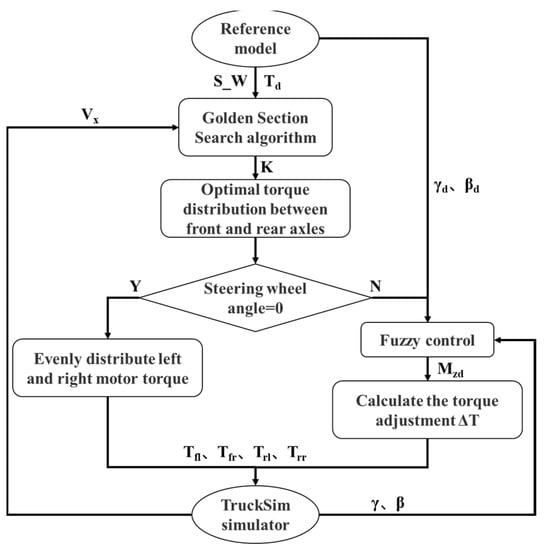
Figure 2.
The structure of the DDEV torque control strategy.
3.1. Torque Distribution of Front and Rear Axles Based on the Optimal Overall Efficiency
The torque distribution problem of the front and rear axles of an electric bus can be converted into the problem of determining the torque distribution coefficient K of the front and rear axles. The torque distribution coefficient K is defined as the ratio of the front axle motor torque and the total demand torque, as follows:
where Tfront is the sum of the motor torques on the left and right sides of the front axle, and Ttotal is the total required torque of the vehicle.
This paper uses the golden section search algorithm to quickly and accurately determine K. The golden section search algorithm is an optimization algorithm with a one-dimensional search dimension, which is mainly used to determine the extreme points of a convex function (or a concave function) in a given interval [a, b]. The convex characteristic (or concave characteristic) in a given interval [a, b] is a sufficient and necessary condition for the correct use of this algorithm.
When the permanent magnet synchronous motor is working, the motor power has the following relationship:
where Pin is the input power, Pout is the output power, and Ploss is the power loss. Ploss includes copper loss PCu, iron loss PFe, and mechanical loss Pm. Pm is generated by the friction torque Tf when the motor is working. The input power of a single motor can be obtained with the following:
where Tout is the motor output torque, ω is the motor speed, and the other parameters can be referred to in Table 2.
In the driving conditions, all of the parameters in the formula are positive numbers, so the total power loss can be expressed as follows:
where af, bf, cf, ar, br, and cr are all positive numbers. Ploss calculates the second-order partial derivative of K:
in the search interval, the value is always greater than 0. In driving conditions, Ploss is a concave function of K.
The overall vehicle efficiency ηtotal can be expressed as follows:
where Ttotal and ω are positive and fixed, and ηtotal is the convex function of the front and rear axle torque distribution coefficient K. The golden section search algorithm can be used.
The optimization objective function used by the algorithm is ηtotal. Here, ηtotal can be calculated by the number of pole pairs of the motor, the stator wire resistance, the inductance, and other internal parameters. The search interval changes according to the real-time operating conditions, because K is a non-negative number in the interval [0,1], and it is guaranteed that the torque does not exceed the maximum load of the motor. Therefore, the left boundary a and right boundary b of the search interval are set as follows:
where Trear_m is the maximum torque of the rear axle at the current speed, and Tfront_m is the maximum torque of the front axle at the current speed.
Figure 3 presents the flow chart of the golden section search algorithm. The total required torque of the current driving conditions and the current speed of each motor are known. Each cycle compares the ηtotal at the two insertion points x1 and x2 in the current search interval. If ηtotal (x1) is superior to ηtotal (x2), the search interval is narrowed. Note that a is equal to x1 and b remains unchanged; otherwise, a remains unchanged and b is equal to x2. Furthermore, the insertion points x1 and x2 are updated. The calculations are made multiple times until the specified search accuracy is reached. Subsequently, the K of the current working condition can be obtained. In this study, the search accuracy ε of the algorithm was set to 0.0001. The insertion points were located at 0.382 and 0.618 of the search intervals, respectively; these were the golden section points. One of the insertion points of the reduced interval was located at the same place as the other insertion point of the interval prior to the reduction, so the calculation of the efficiency value of the insertion point could be omitted. Hence, the calculation efficiency of the algorithm could be improved.
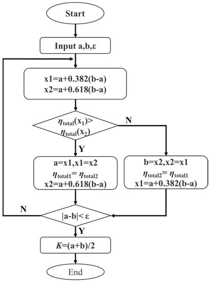
Figure 3.
Golden section search algorithm.
3.2. Torque Distribution Strategy of Left and Right Motors Based on Driving Conditions
The economy was mainly considered in the straight-travel operation of the electric bus, and the average distribution of the left and right wheel torques could achieve the best economic efficiency. According to Ttotal and K, the output torques of the driving wheels are calculated as follows:
where Ti denotes torques of the driving wheels, and i = fl, fr, rl, and rr denote the front-left, front-right, rear-left, and rear-right wheels, respectively.
The optimal distribution of the front and rear axle torques guarantees the optimal economy of the electric bus. However, stability under steering conditions is a key factor that must be considered. Based on the optimal economical torque distribution, this paper uses the direct yaw moment control to distribute the torque of the left and right wheels to ensure economic efficiency and improve vehicle yaw stability.
To obtain the expected yaw moment of the vehicle, a fuzzy controller is designed based on the yaw rate and the side slip angle. The fuzzy controller takes the yaw rate deviation Δγ and the side slip angle deviation Δβ as the input. The fuzzy controller outputs the expected yaw moment Md when turning.
Δγ is the difference between the actual yaw rate γ and the expected yaw rate γd. Δβ is the difference between the actual side slip angle β and the expected slip angle βd:
where γ and β can be obtained through the established TruckSim electric bus model. γd is calculated from the two-degree-of-freedom vehicle model:
where δ is the average steering angle of the front wheels, vx is the longitudinal speed of the vehicle, μ is the road adhesion coefficient, and k is the stability factor, where its expression is as follows:
To enable the vehicle to travel along the desired route, this article believes that the side slip angle should not be too large, and the expected value βd is set to zero.
The fuzzy subset of the yaw rate deviation is [NB, NS, ZE, PS, PB], where NB stands for ‘negative big’, NS stands for ‘negative small’, ZE stands for ‘zero’, PS stands for ‘positive small’, and PB for ‘positive big’. The fuzzy subset of the slip angle is set to the same as the fuzzy subset of the yaw rate. The fuzzy subset of the expected yaw moment Md is [NB, NM, NS, ZE, PS, PM, PB], where NB stands for ‘negative big’, NM stands for ‘negative medium’, NS stands for ‘negative small’, ZE stands for ‘zero’, PS stands for ‘positive small’, PM stands for ‘positive medium’, and PB stands for ‘positive big’. Figure 4a–c shows the membership functions of the yaw rate deviation, the side slip angle deviation, and the expected yaw moment. The expected yaw moment fuzzy inference rules are shown in Table 3. The designed fuzzy controller determines Md in real time according to Δγ and Δβ.
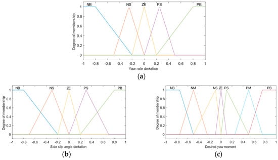
Figure 4.
Membership function: (a) membership functions of the γ deviation; (b) membership functions of the β deviation; (c) expected yaw moment.
Table 3.
Fuzzy inference rules of the expected yaw moment.
The torque adjustment value ΔT of the left and right wheels can be calculated as follows:
The output torque of each of the four motors can be obtained as shown in Equation (14).
4. DDEV Torque Control Strategy Simulation and Analysis
To verify the designed controller, the DDEV torque distribution control model was established to first perform the SIL simulation analysis.
First, the driver model, motor external characteristic model, and DDEV torque control strategy model were established using MATLAB/Simulink. Second, the electric bus model was implemented using TruckSim. Together, these composed the distributed torque control simulation platform for the four-wheel-drive electric bus.
The driver model was composed of the accelerator pedal signal and the steering wheel angle signal. It mainly provided the initial Ttotal and the steering wheel angle. Hence, the external characteristic model of the motor mainly limited the initial Ttotal through the output of the driver model and the current vehicle speed to prevent the motor from overloading. The four-wheel-drive torque control model calculated the four-motor torque input through the TruckSim electric bus model according to the driver’s input signals and the torque distribution strategy.
The four-wheel torque equal distribution is currently the most widely used control strategy for DDEVs. It is simple and easy to implement and it serves as a simulation control group for the torque distribution optimization strategy designed in this study. Simultaneously, to verify the effect of improving the yaw stability of steering conditions, the torque distribution strategy using the golden section search algorithm under all conditions was also used as the simulation control group. The step steering conditions, as well as the sine wave steering conditions, are typical driving conditions. A simulation was carried out under these two conditions.
4.1. Step Steering Conditions
Under the step steering conditions, the accelerator pedal opening input by the driver was reduced from 0.6 to 0.3, and the steering wheel angle remained unchanged at 90° to the left after going straight for 2 s. The initial vehicle speed was set to 45 km/h, and the road adhesion coefficient was set to 0.4. Figure 5a–e shows the longitudinal velocity, the four-wheel torque after optimized distribution, the comparison result of the efficiency, the yaw rate deviation, and the side slip angle deviation using the three distribution strategies.
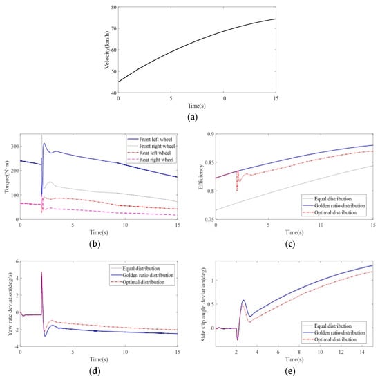
Figure 5.
Simulation results of the step steering conditions: (a) Vx; (b) optimized motor torque after distribution; (c) efficiency; (d) yaw rate deviation; (e) slip angle deviation.
Figure 5a shows that the longitudinal velocity increased from 45 km/h to 74.37 km/h. Figure 5b shows that the front and rear axle motors distributed the total demand torque according to K in the first 2 s of straight driving. Moreover, the left and right wheel torques were equally distributed. After 2 s, the vehicle started to turn. The controller adjusted the left and right wheels based on the best distribution of the front and rear axle torques.
The averages of the efficiency of the three control strategies were 80.78%, 85.62%, and 84.59%, respectively. Figure 5c shows that compared with the four-wheel torque distribution, the efficiency of the torque distribution strategy using the golden section search algorithm under all conditions increased by 4.84%. Under the steering conditions, the torques of the left and right wheels were adjusted. The reason for this is that the overall efficiency of the vehicle decreased slightly. However, compared with the efficiency of the four-wheel torque equal distribution, it was augmented by 3.81%.
The yaw rate and the side slip angle are two significant indicators for evaluating the stability of the vehicle. Figure 5d,e show that the deviation of the yaw rate and the side slip angle were almost 0 when traveling straight in the first 2 s. The expected running trajectory was better tracked without deviation. After 2 s, the left and right wheel torques were adjusted to reduce the deviation between the actual value and the expected value of the yaw rate and the side slip angle. Compared with the four-wheel torque equal distribution and the torque distribution strategy using the golden section search algorithm under all of the conditions, the yaw stability improved significantly.
4.2. Sine Wave Steering Conditions
To verify the improvement effect of the control strategy on the yaw stability under the condition of large turning angles and frequent changes in the turning angle, the sine wave steering conditions were designed for simulation verification. The accelerator pedal opening input by the driver was reduced from 0.5 to 0.2, the steering wheel angle changed at ±120°, the initial vehicle speed was 45 km/h, and the road adhesion coefficient was set to 0.4. Figure 6a–e shows the longitudinal velocity, the four-wheel torque after optimized distribution, the comparison result of the efficiency, and the yaw rate deviation and the side slip angle deviation using the three distribution strategies.
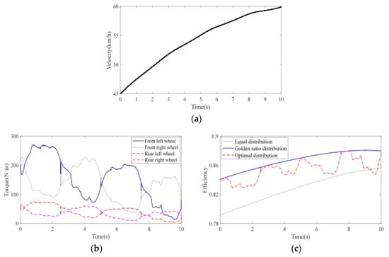
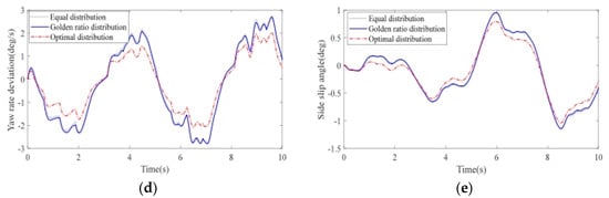
Figure 6.
Simulation results of the sine wave steering conditions: (a) Vx; (b) optimized motor torque after distribution; (c) efficiency; (d) yaw rate deviation; (e) slip angle deviation.
It can be seen from Figure 6a that the longitudinal velocity increased from 45 km/h to 59.84 km/h. Moreover, Figure 6b shows that to improve the yaw stability, as the steering wheel angle increased, the left and right wheel torque adjustment value ΔT was augmented accordingly.
The averages of the efficiency for the three control strategies were 82.85%, 86.68%, and 85.32%. Furthermore, Figure 6c shows that compared with the four-wheel torque equal distribution, the efficiency of the torque distribution strategy using the golden section search algorithm under all conditions and the optimized distribution algorithm increased by 3.83% and 2.47%, respectively. From Figure 6d,e, it is clear that adjusting the left and right wheel torques significantly reduced the deviation of the yaw rate and the deviation of the side slip angle, and the yaw stability improved. Moreover, in comparison with the torque distribution strategy using the golden section search algorithm, under all conditions, the efficiency value decreased with the increase in the left, and the right wheel torque adjustment value ΔT.
5. HIL Test and Analysis
Although the SIL simulation results show that the torque distribution strategy proposed in this study improved the overall efficiency of DDEV, when the computer was used for MATLAB/Simulink and TruckSim co-simulation, the calculation step was set to 1 ms or even shorter. However, under the existing technical conditions, the actual calculation period of the control system was generally 10 ms or even longer. Subsequently, there will be data frame loss when communicating between nodes in the control network. Therefore, it is necessary to conduct further HIL tests on the proposed torque distribution strategy before the application on a real vehicle.
The HIL test system architecture of the four-wheel-drive torque controller is shown in Figure 7. The real-time version of TruckSim was used to simulate the real-time wheel-side four-wheel-drive electric bus dynamics model and virtual driving scene. DSP28335 was employed to make a four-wheel drive torque controller, which calculated and distributed the torque of the four drive motors in real-time. The NI_PXIe-1085 chassis equipped with a PXI-8512CAN interface module was used to receive feedback signals and send four motor torque signals to control the electric bus.
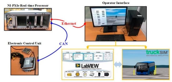
Figure 7.
The HIL Test System.
5.1. Step Steering Conditions
Based on the simulation analysis of Section 4.1, the test used the same working conditions to further verify the feasibility of the torque optimal distribution strategy. Figure 8a–e shows a comparison of the results using three control strategies under step steering conditions.
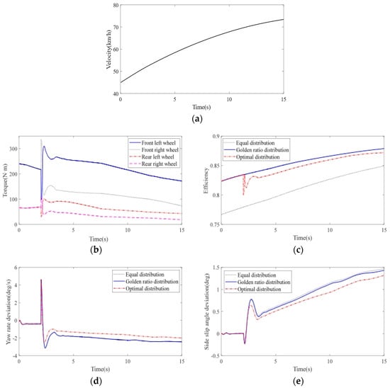
Figure 8.
HIL test results of the step steering conditions: (a) Vx; (b) optimized motor torque after distribution; (c) efficiency; (d) yaw rate deviation; (e) slip angle deviation.
It can be seen from Figure 8a that the longitudinal velocity increased from 45 km/h to 73.43 km/h, which was slightly lower than the simulation result, mainly due to a certain delay in the HIL test calculation at the beginning of the simulation. On the other hand, the torque distribution results in Figure 8b were consistent with the SIL simulation results.
The averages of the efficiency of the three control strategies were 81.10%, 85.55%, and 84.85%. Figure 8c shows that the torque distribution efficiency of the torque distribution strategy using the golden section search algorithm under all conditions increased by 4.35% in comparison with the four-wheel torque equal distribution. The strategy of optimizing the adjustment and distribution of the left and right wheels improved by 3.75% compared with the four-wheel torque distribution, which is consistent with the SIL simulation results. Figure 8d,e is consistent with the SIL simulation results. In comparison with the simulation results, the HIL test results maintained a better consistency, which indicates that the proposed torque distribution strategy was controlled in real-time under step steering conditions and was able to achieve the expected optimization effect on the overall performance of the vehicle.
5.2. Sine Wave Steering Conditions
To further verify the effectiveness of the torque distribution strategy proposed in this paper under the condition of a large turning angle and continuously changing steering wheel angle, the HIL test was carried out with the same sine wave steering working condition, as given in the simulation in 4.2. Figure 9a–e shows the comparison results of the HIL test under the sine wave steering working conditions of the three control strategies.
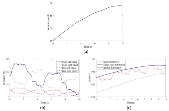
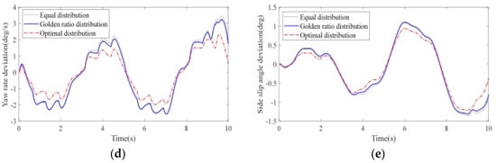
Figure 9.
HIL test results of the sine wave steering conditions: (a) Vx; (b) optimized motor torque after distribution; (c) efficiency; (d) yaw rate deviation; (e) slip angle deviation.
Figure 9a shows that the longitudinal velocity increased from 45 km/h to 59.24 km/h. The averages of the efficiency of the three control strategies were 82.89%, 86.72%, and 85.63%. Moreover, Figure 9c shows that the torque distribution efficiency of the torque distribution strategy using the golden section search algorithm under all conditions increased by 3.83% compared with the four-wheel torque equal distribution. The strategy of optimally adjusting the distribution of the left and right wheels improved by 2.74% in comparison with the four-wheel torque distribution. Figure 9d,e shows that after adjusting the left and right wheel torque, the deviation of the yaw rate and the actual value of the side slip angle were significantly reduced when the rotation angle value was large. Note that the HIL test results were consistent with the SIL simulation results.
The results successfully verified that the torque distribution strategy proposed in this study distributed the torque of each wheel in real-time during the driving process of the vehicle, improving the economy and the yaw stability of the vehicle.
6. Conclusions
Given the poor economy and failure problems of switching control due to both linear and steering conditions, this study suggested a new fuzzy yaw moment control strategy based on the golden section search. Under full working conditions, according to the efficiency characteristics of the front- and rear-axle drive motors, the golden section search algorithm was used to determine the best front- and rear-axle motor torque distribution coefficient K. K was used to distribute the front- and rear-axle motor torques, which were able to achieve the best economy of the vehicle. Given the stability problems under steering conditions and based on the optimal distribution of the front and rear axles, fuzzy control was employed to calculate the expected yaw moment, and the left and right wheel torques were adjusted in real-time, which not only guaranteed the yaw stability during steering, but also achieved the best economy of the vehicle without switching the control.
Under step steering conditions and sine wave steering conditions, SIL simulation and HIL testing were carried out using the three control strategies, four-wheel torque equal distribution, torque distribution strategy using the golden section search algorithm under all conditions, and the torque distribution strategy proposed in this study to verify the improvement of the economy and the yaw stability. The results show that compared with the four-wheel torque equal distribution algorithm, the torque distribution control strategy designed in this study significantly improved the economy and the yaw stability; under steering conditions, the economy was reduced in comparison with the torque distribution strategy using the golden section search algorithm under all of the conditions. However, the yaw stability was improved.
Regarding the construction of the hardware-in-the-loop test bench, there was still room for improvement in this study. The hardware-in-the-loop platform built by Liu Gang et al. [25] combines some hardware systems, such as driving simulators, with computer simulation software systems. The hardware part can accurately reflect the mechanical characteristics and hydraulic characteristics of the system, and the simulation software can simulate various road conditions so as to verify the validity and reliability of the yaw moment control algorithm. In order to verify the effectiveness of the dual steering direct yaw moment control strategy for in-wheel motor-driven vehicles, Yang et al. [26] integrated the driver operating system, the actual vehicle central controller, and other hardware into the built hardware-in-the-loop test platform. Based on the above literature, this study will continue to optimize the construction of the HIL bench.
Author Contributions
Conceptualization and methodology, L.Q.; investigation and formal analysis, D.L.; validation and writing—original draft preparation, Z.X. and H.F.; supervision and writing—review and editing, H.C.; funding acquisition, S.Z. All authors have read and agreed to the published version of the manuscript.
Funding
We gratefully acknowledge the financial support of this research by the following projects: control design of new energy vehicle air conditioning compressor based on intelligent multi-objective optimization (grant no. ZDLQ2020002), research on the theory and method of autonomous cooperative operation control of high-speed trains (grant no. U1934221), and research and manufacture of high precision grinding process of wear-resistant seals of construction machinery (grant no. ZDLQ2021005).
Institutional Review Board Statement
Not applicable.
Informed Consent Statement
Not applicable.
Data Availability Statement
Not applicable.
Conflicts of Interest
The authors declare no conflict of interest.
References
- Park, G.; Han, K.; Nam, K.; Kim, H.; Choi, S.B. Torque vectoring algorithm of electronic-four-wheel drive vehicles for enhancement of cornering performance. IEEE Trans. Veh. Technol. 2020, 99, 3668–3679. [Google Scholar] [CrossRef]
- Guo, N.; Zhang, X.; Zou, Y.; Lenzo, B.; Zhang, T. A computationally efficient path following control strategy of autonomous electric vehicles with yaw motion stabilization. IEEE Trans. Transp. Electrif. 2020, 99, 728–739. [Google Scholar] [CrossRef]
- Guo, N.; Lenzo, B.; Zhang, X.; Zou, Y.; Zhai, R.; Zhang, T. A real-time nonlinear model predictive controller for yaw motion optimization of distributed drive electric vehicles. IEEE Trans. Veh. Technol. 2020, 69, 4935–4946. [Google Scholar] [CrossRef]
- De Filippis, G.; Lenoz, B.; Sorniotti, A. Energy efficient torque vectoring control of electric vehicles with multiple drivetrains. IEEE Trans. Veh. Technol. 2018, 67, 4702–4715. [Google Scholar] [CrossRef]
- Jiang, X.; Chen, L.; Xu, X.; Cai, Y.; Li, Y.; Wang, W. Analysis and optimization of energy efficiency for an electric vehicle with four independent drive in-wheel motors. Adv. Mech. Eng. 2018, 10, 1–9. [Google Scholar] [CrossRef]
- Pennycott, A.; de Novellis, L.; Sabbatini, A.; Gruber, P.; Sorniotti, A. Reducing the motor power consump-tions of a four-wheel drive, fully electric vehicle via wheel torque allocation. Proc. Inst. Mech. Eng. Part D-J. Automob. Eng. 2014, 228, 830–839. [Google Scholar] [CrossRef]
- Chen, Y.; Wang, J.M. Design and experi-mental evaluations on energy efficient control allocation methods for overactuated electric vehicles: Longitudinal motion case. IEEE/ASME Trans. Mechatron. 2014, 19, 538–548. [Google Scholar] [CrossRef]
- Wang, J. Wheel torque distribution optimization of four-wheel independent-drive electric vehicle for energy efficient driving. Control Eng. Pract. 2021, 110, 104779. [Google Scholar] [CrossRef]
- Sar, H.; Renc’ski, A.; Pokorski, J. Investiga-tion of the tyre characteristics under non-steady-state conditions on the basis of road tests. Proc. Inst. Mech. Eng. Part D-J. Automob. Eng. 2016, 231, 3–15. [Google Scholar] [CrossRef]
- Pennycott, A.; Novellis, L.D.; Gruber, P.; Sorniotti, A. Sources of energy loss during torque-vectoring for fully electric vehicles. Int. J. Veh. Des. 2014, 67, 157–177. [Google Scholar] [CrossRef]
- Li, J.; Yang, S.; Li, Z.; Guo, L. An Energy Conservation Strategy Based on Drive Mode Switching for Multi-Axle In-wheel Motor Driven Vehicle. Energy Procedia 2019, 158, 2580–2585. [Google Scholar] [CrossRef]
- Wang, Y.; Fujimoto, H.; Hara, S. Torque Distribution-based Range Extension Control System for Longitudinal Motion of Electric Vehicles by LTI Modeling with Generalized Frequency Variable. IEEE/ASME Trans. Mechatron. 2016, 21, 443–452. [Google Scholar] [CrossRef]
- Sun, W.; Wang, J.; Wang, Q.; Assadian, F.; Fu, B. Simulation investigation of tractive energy conservation for a cornering rear-wheel-independent-drive electric vehicle through torque vectoring. Sci. China Technol. Sci. 2018, 61, 257–272. [Google Scholar] [CrossRef]
- Ding, X.L.; Wang, Z.P.; Zhang, L. Powertrain Sizing for Four-wheel-independent-actuated Electric Vehicles Based on Multi-Objective Optimization. J. Mech. Eng. 2021, 57, 195–204. [Google Scholar]
- Ma, X.J.; Wang, K.Y.; Liu, C.G.; Zhang, Z. Control Method of Stability and Torque Distribution of Military Electric Vehicle with Multi-Wheel. J. Ordnance Equip. Eng. 2020, 41, 85–90. [Google Scholar]
- Zhang, X.D.; Göhlich, D.; Li, J. Energy-efficient toque allocation design of traction and regenerative braking for distributed drive electric vehicles. IEEE Trans. Veh. Technol. 2017, 67, 285–295. [Google Scholar] [CrossRef]
- Fujimoto, H.; Harada, S. Model-based range extension control system for electric vehicles with front and rear driving–braking force distributions. IEEE Trans. Ind. Electron. 2015, 62, 3245–3254. [Google Scholar] [CrossRef]
- Kobayashi, T.; Katsuyama, E.; Sugiura, H.; Ono, E.; Yamamoto, M. Direct yaw moment control and power consumption of in-wheel motor vehicle in steady-state turning. Veh. Syst. Dyn. 2017, 55, 104–120. [Google Scholar] [CrossRef]
- Dadashnialehi, A.; Bab-Hadiashar, A.; Cao, Z.; Kapoor, A. Intelligent sensorless ABS for in-wheel electric vehicles. IEEE Trans. Ind. Electron. 2014, 61, 1957–1969. [Google Scholar] [CrossRef]
- Kobayashi, T.; Katsuyama, E.; Sugiura, H.; Ono, E.; Yamamoto, M. Efficient direct yaw moment control: Tyre slip power loss minimization for four-independent wheel drive vehicle. Veh. Syst. Dyn. 2018, 56, 719–733. [Google Scholar] [CrossRef]
- Chen, Y.; Hedrick, J.K.; Guo, K. A novel direct yaw moment controller for in-wheel motor electric vehicles. Veh. Syst. Dyn. 2013, 51, 925–942. [Google Scholar] [CrossRef]
- Li, Y.; Zhang, J.; Lv, C.; Yuan, Y. Coordinated control of the steering system and the distributed motors for comprehensive optimization of the dynamics performance and the energy consumption of an electric vehicle. Proc. Inst. Mech. Eng. Part D-J. Automob. Eng. 2017, 231, 1605–1626. [Google Scholar] [CrossRef]
- Chen, Y.; Wang, J.M. Adaptive energy-efficient control allocation for planar motion control of over-actuated electric ground vehicles. IEEE Trans. Control Syst. Technol. 2014, 22, 1362–1373. [Google Scholar]
- Gu, J.; Ouyang, M.; Lu, D.; Li, J.; Lu, L. Energy efficiency optimization of electric vehicle driven by in-wheel motors. Int. J. Automot. Technol. 2013, 14, 763–772. [Google Scholar] [CrossRef]
- Liu, G.; Jin, L.Q.; Wang, Y. Vehicle stability control system based on active disturbance-rejection control strategy. J. Zhejiang Univ. Eng. Sci. 2016, 50, 2289–2296+2379. [Google Scholar]
- Yang, G.B.; Ma, X.J.; Liao, Z.L.; Liu, C.G. Direct Yaw Moment Control in Dual-steering for In-wheel Motor Drive Vehicle. Acta Armamentarii 2016, 37, 211–218. [Google Scholar]


Publisher’s Note: MDPI stays neutral with regard to jurisdictional claims in published maps and institutional affiliations. |
© 2022 by the authors. Licensee MDPI, Basel, Switzerland. This article is an open access article distributed under the terms and conditions of the Creative Commons Attribution (CC BY) license (https://creativecommons.org/licenses/by/4.0/).