Abstract
In this paper, we propose an area- and power-efficient reconfigurable architecture for multifunction evaluation based on an optimized piecewise linear (PWL) method. The proposed segmentor automatically divides nonlinear functions into the fewest segments with a predefined maximum absolute error (MAE) and fractional bit width of the slope. In addition, a multiplier was optimized via Booth encoding to reduce the number of rows in the partial product matrix. Compressors were used to shorten the critical path. The results of application-specific integrated circuit (ASIC) implementation reveal that all metrics of the proposed architecture are improved for single functions, without any compromise. Moreover, reconfigurable technology was introduced for implementing multiple functions while reusing computing resources. Compared to a corresponding architecture without reuse, the area and power of this reconfigurable architecture are reduced by 37.48% and 45.60%, respectively, at the same frequency.
1. Introduction
Complex function computations have been widely deployed in computer graphics, digital signal processing and machine learning [1,2]. For example, logarithmic and exponential functions are essential in graphics processing units [3]. Other complex functions, such as reciprocal, square root and inverse square root functions, are widely used in the inference and training of deep neural networks (DNNs), which are widely applied in natural language processing and video processing [4]. Generally, different complex functions are computed by different algorithms to pursue a high performance. For example, the COordinate Rotation DIgital Computer (CORDIC) algorithm is adept at computing logarithmic, exponential and square root functions, whereas the Newton–Raphson (NR) iteration method is used in the computation of reciprocal and inverse square root functions. Different algorithms occupy different hardware resources. Thus, hardware resources often cannot be shared among different complex functions, leading to a low utilization efficiency of hardware resources. To enable the reuse of hardware resources among different complex functions, a universal method for computing complex functions is essential. The piecewise linear (PWL) approximation method is such a universal method.
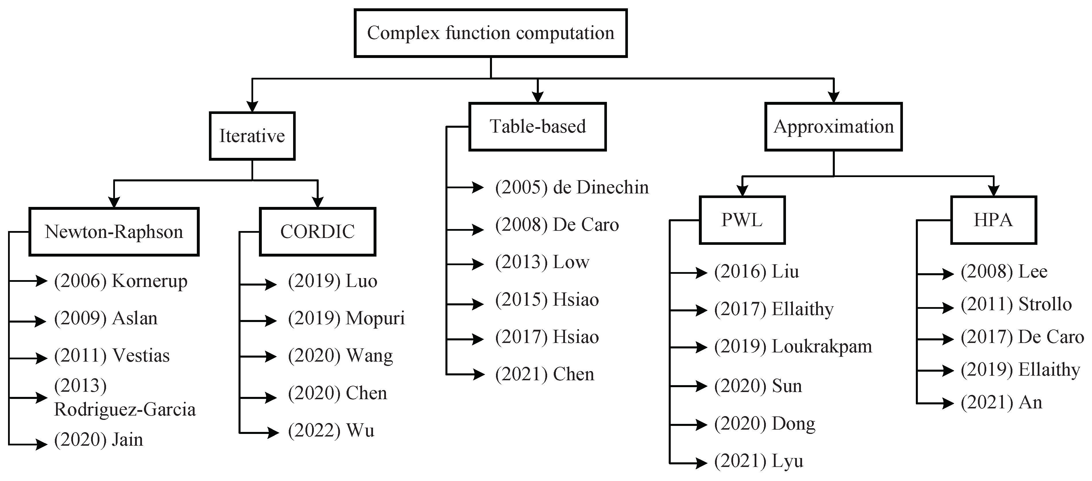
The methods of computing complex functions are listed in Figure 1. There are three categories: iterative, table-based and approximation methods. The iterative NR and CORDIC methods are two frequently used algorithms. Approximation methods are also further classified into two types: PWL approximation and high-degree polynomial approximation (HPA). Among the above methods, CORDIC can be used to implement only some of the complex functions of interest, such as logarithmic and exponential functions [5,6,7,8,9]. The other methods are universally applicable to various complex functions. However, the hardware implementations of different complex functions based on the NR method employ different computing resources, which consequently cannot be shared between different complex functions [10,11,12,13,14]. The main hardware overhead of a table-based method is the storage space for precalculated results [15,16,17,18,19,20]. However, these storage spaces are independent between different complex functions. Accordingly, although the computing resources can be shared, the overall reuse ratio of hardware resources is still low. In addition, HPA suffers from high hardware overhead and delay because of its usage of many cascaded multiplication and addition operations [21,22,23,24,25]. In contrast, the PWL method requires only one multiplication and one addition operation, with a low delay and simple circuit architecture [3,26,27,28,29,30].
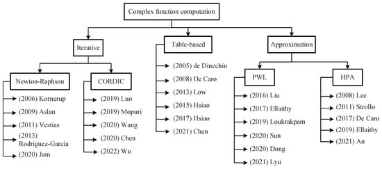
Figure 1.
Taxonomy of related works on complex function computation.
The PWL approximation approach is widely used in the computation of nonlinear unary functions with low- or medium-accuracy requirements. In this approach, a nonlinear function is divided into a number of segments. In each segment, the nonlinear function is approximated by a linear function expressed as , where k and b are the slope and y-intercept, respectively, of the linear function. Most studies on the PWL method tend to focus on its use for one specific function or class of functions, such as logarithmic or antilogarithmic functions [3,26,27]. Ref. [28] proposed a general PWL approximation method for transcendental functions. This work was innovative and broadened the application scenarios of the PWL method, improving its universality. In addition, this method has a self-adaptive capability to determine the broadest acceptable segments under a maximum absolute error (MAE) constraint. This method was enhanced in [29] and named piecewise linear approximation computation (PLAC). Specifically, a novel quantizer was proposed to completely simulate the hardware behavior and determine the bit width required under a given MAE restriction for hardware implementation. Based on PLAC, the segmentation performance and quantification performance can be optimized by inserting this quantification operation into the segmentor [30]. Although this method has only been used to implement logarithmic computations on floating-point numbers, it can easily be generalized to other unary functions.
Currently, low-precision computation is adopted to pursue a low latency in many fields, such as speech recognition, machine learning and signal processing [31,32,33]. The half-precision floating-point format (FP16) is suitable for this kind of application. In this article, we focused on the implementation of multifunction evaluations in FP16. A reconfigurable architecture for multifunction computation was implemented by reusing computing units to achieve a high computation density. We proposed a segmentor to divide nonlinear functions into a suitable number of segments under restrictions on the MAE and the fractional bit width of the slope. The predefined MAE was set to to ensure an accuracy within one unit in the last place (ulp). For numerical calculations, accuracy is often measured in units of ulp [34]. If the fractional bit width is qw, an accuracy of 1 ulp means that MAE is smaller than . We adopted the constraint that the MAE of the hardware must be less than the predefined value. Compared to the segmentor in [30], the proposed segmentor keeps the fractional bit widths of b and the same as those of the input to avoid truncation after the optimization of b. In addition, the fractional bit width of k is varied to balance it with the number of segments. The proposed segmentor uses a similar number of segments with a smaller fractional bit width of k to achieve the same accuracy as in [30]. In the hardware architecture, the Booth encoding method is used to reduce the number of partial products, and compressors are devoted to reducing the critical path. We used the proposed approach to implement five nonlinear functions that frequently appear in computer graphics and DNN applications [3,35,36]: , , , and , where the input f is the mantissa part of an FP16 value, with a range of [0, 1) and a word length of 10 bits. The hardware architectures for these five functions were coded in the Verilog hardware description language (HDL) and synthesized in TSMC 65 nm technology. The synthesized results show that all metrics of the the proposed approach are improved, without any compromise, compared to the state-of-the-art architecture in [30]. The proposed architecture for saves a 7.58% delay, 9.16% area and 17.90% power. For , a 4.48% delay reduction, a 55.64% area reduction and a 54.85% power reduction are achieved. For , a 22.39% delay improvement, a 34.38% area improvement and a 28.64% power improvement are achieved. For , the delay, area and power are reduced by 31.88%, 44.10% and 36.62%, respectively. In addition, our implementation has a 25.81% delay improvement, a 47.77% area improvement and a 43.59% power improvement.
Based on the proposed segmentor and the hardware architectures for single functions, we also introduced reconfigurable technology for multifunction implementation by reusing computing resources such as adders. Compared to a corresponding architecture without reuse, this reconfigurable architecture saves 37.48% area and 45.60% power at 1.25 GHz.
The highlights of this article are summarized as follows.
- The proposed segmentor reduces the bit width of the slope after quantification. It uses a similar number of segments with a smaller bit width of the slope to achieve the same precision as in [30].
- The hardware architecture for a single function was optimized by means of Booth encoding to reduce the number of partial products. Additionally, compressors were introduced to shorten the critical path.
- The hardware performance of the proposed architecture for a single function exhibits clear improvements over state-of-the-art approaches in terms of area, power, latency and so on.
- Reconfigurable technology was applied for multifunction implementation by reusing computing resources to improve the computing density.
The rest of this paper is organized as follows: Section 2 introduces the theory of the PWL method and its precision metrics. Section 3 analyzes the proposed software-based segmentor in detail. Section 4 presents the details of our proposed architecture for single and multiple functions. In Section 5, we compare the implementation results of our hardware architectures for single functions with the state-of-the-art implementations. Additionally, we compare our proposed multifunction architecture that reuses computing resources against a corresponding architecture without reuse. Section 6 concludes the article.
2. Theoretical Background
2.1. PWL Method
In the PWL method, the nonlinear function is divided into several segments. In the segment, is approximated by a linear function
where and are the slope and y-intercept, respectively. The precision of the PWL approximation depends on , and the width of the segments.
MAE is an important precision metric for evaluating the PWL method. The MAE of the PWL method is defined as
where is the actual value of the nonlinear function and is the value approximated by the PWL method.
2.2. Minimization of MAE
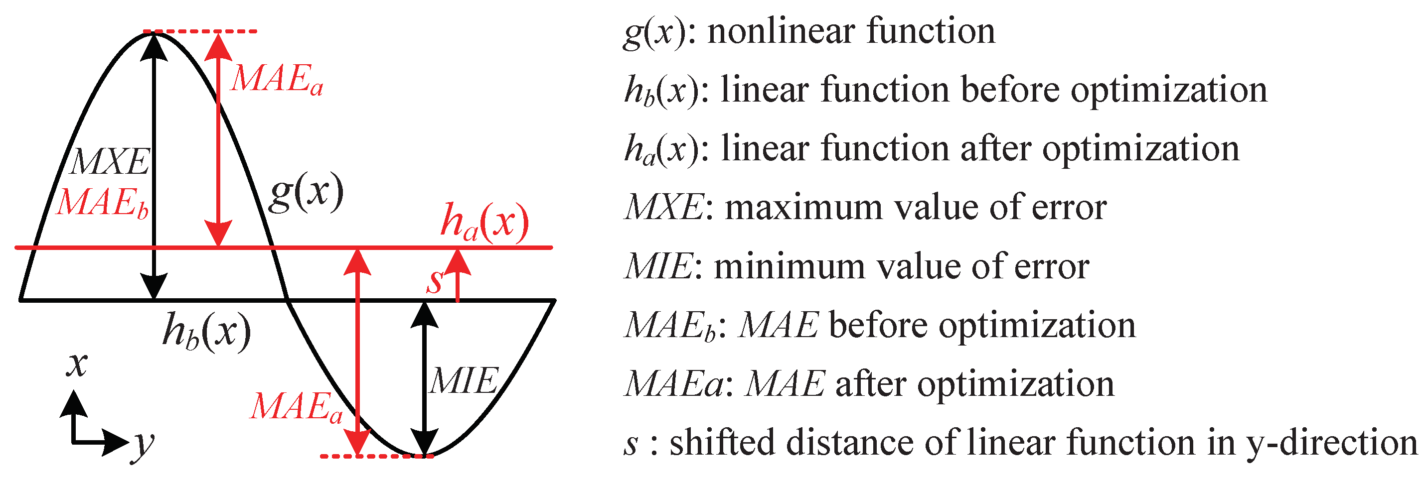
As shown in Figure 2, when the maximum and minimum error values (MXE and MIE) are not balanced, MAE can be decreased. The error e in the segment can be expressed as
where sp and ep are the starting and ending points, respectively, of the inputs in the segment. MXE and MIE are expressed as
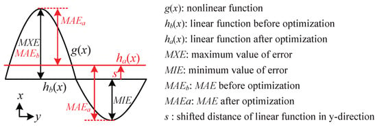
Figure 2.
MAE is minimized by shifting the linear function in the y-direction.
Accordingly, the MAE value before optimization can be expressed as
In the case where the linear function is shifted in the y-direction by s, the new MXE and MIE are expressed as
Notably, MAE is minimized when the new MXE and MIE have the following relationship:
Therefore, the shift distance s in the y-direction is obtained as
The expression for the linear function in (1) after shifting s units in the y-direction is updated to
where
After optimization, MAE is minimized to
This optimization operation effectively reduces the MAE contribution that arises due to unbalanced positive and negative values.
2.3. Software-Based Segmentor
In [28], a universal segmentor for the PWL method was proposed to choose the smallest number of segments that can satisfy the predefined MAE requirement of the software. Ref. [29] further optimized the segmentor in [28]. In addition, a quantizer used to determine the smallest fractional bit width under the MAE constraint of the hardware circuit has been proposed. To improve the segmentation and quantification performance, these quantification operations are embedded into the segmentor in [30]. Although the segmentor in [30] is designed for logarithmic computations on floating-point numbers, it can easily be used in the computation of other nonlinear functions, such as logarithmic, exponential, reciprocal, square root and inverse square root functions.
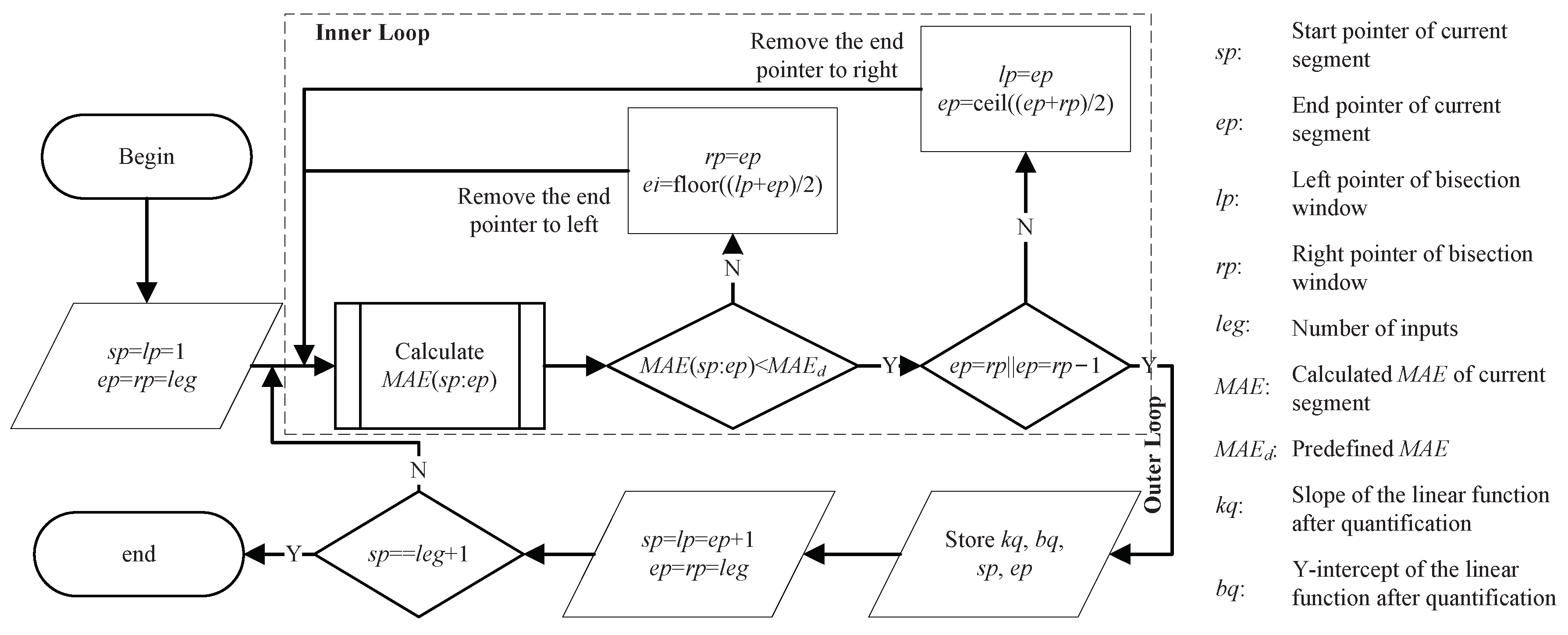
The procedure of the segmentor in [30] is illustrated in Figure 3. The segmentor divides the given nonlinear function into several segments subject to a predefined MAE constraint, . The MAE of the hardware circuit based on the segmentor result must be no larger than . When calculating , the segmentor also considers the quantification operation. The quantification errors are also included in the calculated MAE in addition to the segmentation errors.
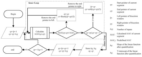
Figure 3.
Procedure of the segmentor in [30].
3. Proposed Approach
In this section, the mantissa part of an FP16 value, f, was taken as the input. The value of f lies in the range of [0, 1), and the length of f is 10 bits. The five nonlinear functions , , , and were taken as the target functions in our proposed approach. Furthermore, is always set to to provide an accuracy within 1 ulp. We analyzed the performance of the segmentor in [30] and our proposed segmentor. The segmentors were modeled in MATLAB R2019a running on a Dell XPS 13 laptop with an Intel(R) Core(TM) i7-10710U CPU and 16 GB of RAM. The segmentor parameters were also selected based on the relationship between the fractional bit width and the number of segments.
3.1. Proposed Segmentor
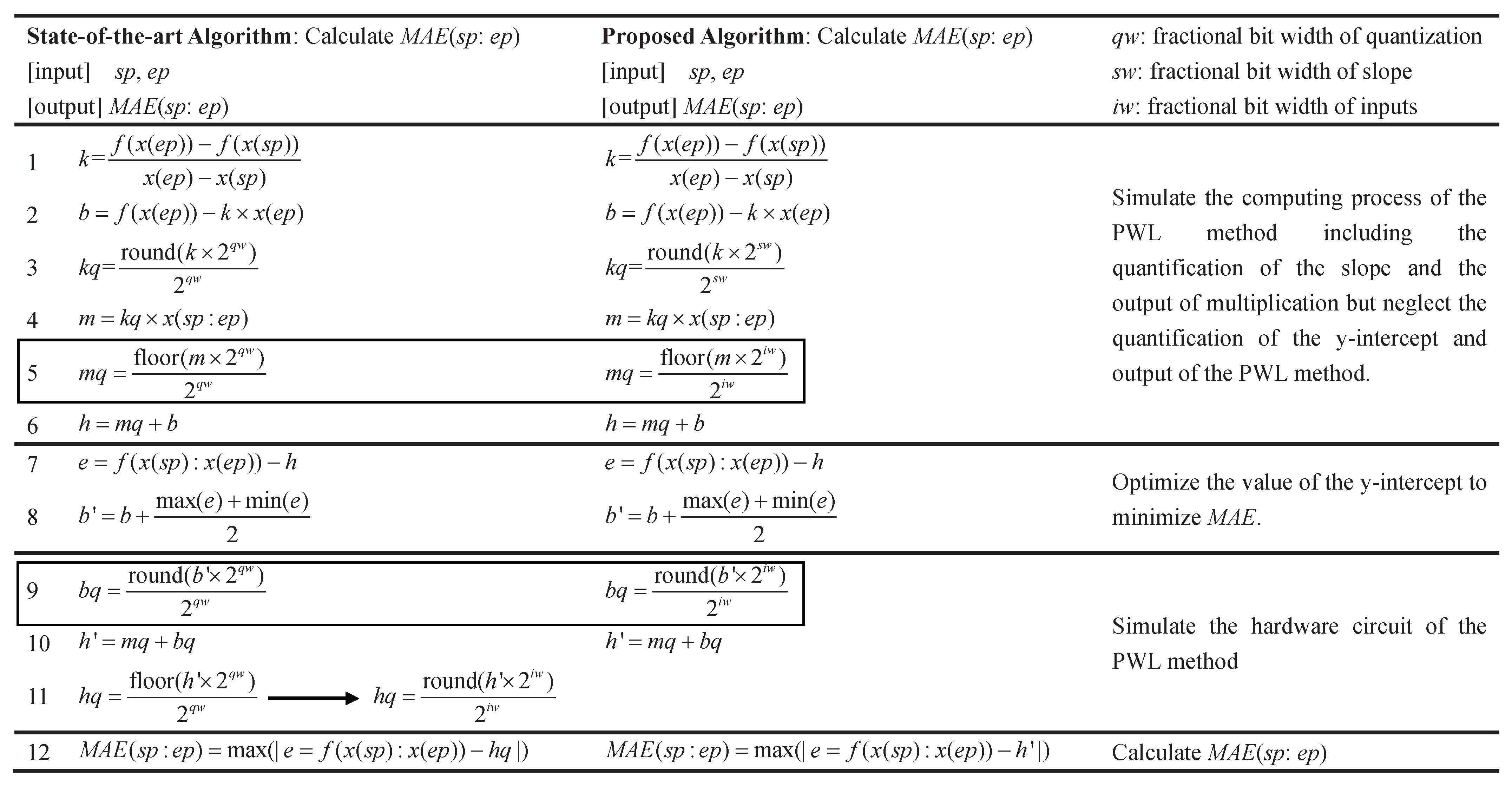
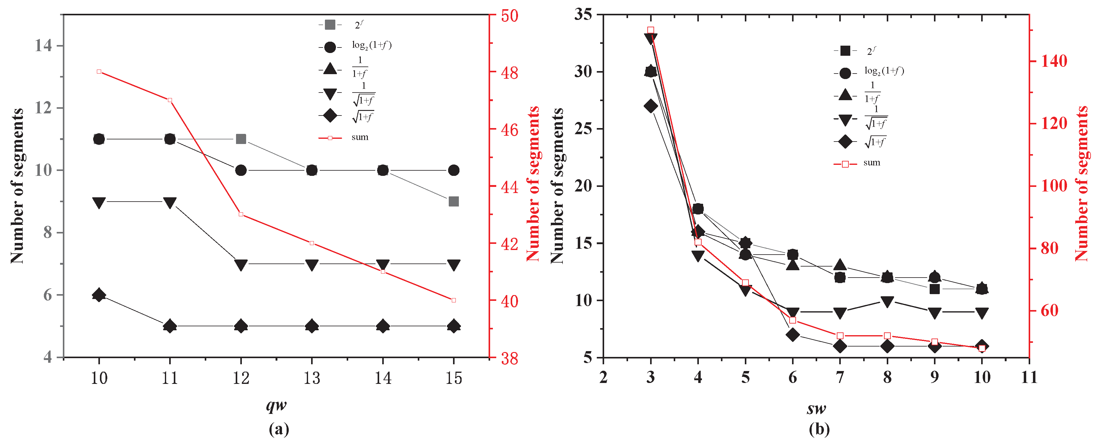
Although the segmentor used in [30] is designed for the implementation of logarithmic computations on floating-point numbers, it can easily be generalized to any unary function. The critical procedure of such a segmentor is the calculation of , which is the optimized part of our design. As shown in Figure 4, we first translated the segmentor in [30] so that it is suitable for our design. In our design, the fractional word length of the output corresponds to that of the input, iw. The output was rounded to a fractional bit width iw in line 11 of Figure 4. This operation reduces the error but incurs extra hardware overhead compared to truncation methods. We used different values of qw in the segmentor to divide the five target nonlinear functions into various numbers of segments. The relationship between qw and the number of segments is illustrated in Figure 5a. The number of segments decreases with an increasing qw.
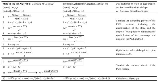
Figure 4.
Algorithm for the state-of-the-art segmentor in [30] and the proposed segmentor.
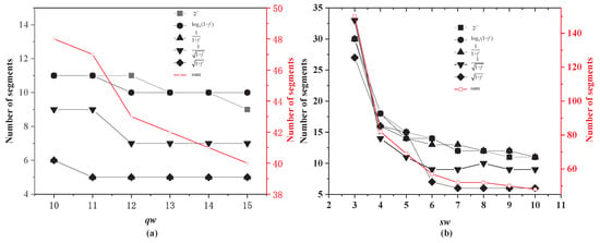
Figure 5.
(a) Numbers of segments obtained with different qw settings by the segmentor proposed in [30]. (b) Numbers of segments obtained with different sw settings by the proposed segmentor.
As seen from Figure 5a, a large qw results in only a small decrease in the number of segments. If qw is less than 10, then the segmentor cannot converge. Given the small benefit of a large qw, qw was set to its smallest possible value of 10, which is the same as the value of iw. However, the multiplier requires a large hardware overhead. Hence, the bit width of the slope was separately considered to reduce the bit width of the multiplication. The proposed algorithm for calculating is shown in Figure 4. The output of the multiplication and the optimization of the y-intercept were quantified with a fractional bit width of iw. Therefore, their sum also has a fractional bit width of iw without truncation. In the proposed algorithm, only the slope has a different fractional bit width from the other data. The fractional bit width of the slope is sw, and the fractional bit widths of the other data are all iw, as shown in Figure 6. We used the proposed segmentor to divide the five target nonlinear functions into various numbers of segments, as shown in Figure 5b. A large sw is beneficial for reducing the number of segments.

Figure 6.
Computational flow of the proposed PWL method. The numbers under the computing units are the lines of the corresponding simulation code in Figure 4.
The procedure of the proposed segmentor is similar to that in Figure 3, except for the subprocedure of calculating MAE in the current segment. Therefore, we introduce the proposed algorithm for calculating in detail as follows.
- (1)
- Calculate the slope and y-intercept of the current segment based on the starting and ending points as follows:The slope was quantified by rounding to the nearest value with a fractional bit width of qw. If the first truncated bit is 0, then the lower bits were directly truncated. Otherwise, one carry was added after truncation. For example, the binary number 1.10101 can be quantified with three fractional bits by rounding it to 1.101. In contrast, the binary number 1.10110 can be quantified as 1.110. Obviously, rounding quantification has a low accuracy loss but more hardware overhead. It is suitable for data that are prepared by a software platform and stored on a chip under design. In our design, the slope and y-intercept were quantified by means of a rounding operation. In the segmentor, the operation of quantification by rounding was simulated asCorresponding to the first binary number, 1.65625 () in decimal format was quantified as 1.625 () according to (16), whereas 1.6875 () was quantified as 1.75 (). Thus, it can be seen that the simulation for decimal numbers expressed in (16) agrees with the rounding quantification operation for binary numbers. Accordingly, the multiplication output can be simulated asThis output is provided as an input for addition. Hence, it must also be quantified to reduce the width of the adder. To avoid truncating the output after minimizing MAE by shifting the linear function in the y-direction, m was quantified to a fractional bit width of iw, which is the same as that of the input. The quantification of m was also executed by the hardware circuit. To avoid an increase in hardware overhead, m was directly quantified via truncation. The lower bits were directly truncated without considering carry operations. For example, the binary numbers 1.10101 and 1.10110 were both quantified as 1.101 by truncation to three fractional bits. The operation of quantification by truncation was simulated asCorresponding to the same binary numbers considered above, 1.65625 () and 1.6875 () in decimal format were both quantified as 1.625 () according to (18). Therefore, by neglecting the quantification and optimization of the y-intercept, the output of the linear function can be expressed as
- (2)
- (3)
- Simulate the multiplication by means of (14)–(18). Accordingly, the y-intercept should be quantified before the addition operation. The quantification operation for the y-intercept is also based on rounding to the same fractional bit width as the input. The quantitative simulation of the y-intercept is expressed asHence, the expression for the linear function was updated to
- (4)
- Calculate MAE with (2).
In step (3), we used software to simulate the computational flow in Figure 6. Therefore, the MAE obtained in step (4) is equal to the MAE of the hardware circuit if the parameters of the circuit are set in accordance with the current segment.
3.2. Performance Analysis and Parameter Selection
As seen from Figure 5a, a larger qw leads to a decrease in the number of segments, and a segmentor with qw less than 10 cannot converge to an accuracy of 1 ulp. However, the reduction in the number of segments is clearly very small. Therefore, the value of qw in the segmentor of [30] was set to 10 for comparison with our proposed segmentor.
In our proposed segmentor, the fractional bit width of the slope, sw, only controls the bit width of one input to the multiplication operation. Because the fractional bit width of the input, iw, is 10, we also used iw as the fractional bit width of data other than the slope. When sw is 10, our proposed segmentor obtains the same number of segments as the segmentor of [30]. When sw is less than 10, our segmentor also works well, with an increase in the number of segments. In our design, we selected the value of sw corresponding to the start of the flat part of each line in Figure 5b. The selected values of sw and the corresponding numbers of segments are listed in Table 1.

Table 1.
Selected values of sw in our proposed architecture and corresponding parameters.
In a multifunction implementation that reuses computing resources, the various computing resources should have the same bit width. Therefore, we considered the sum of the numbers of segments for all functions. The flat part of the sum line starts when sw is equal to 6. Therefore, sw was set to 6 to obtain the parameters for the multifunction implementation with the reuse of computing resources. Additionally, we list the segment information for our proposed segmentor with an sw of 6 in Table 1.
3.3. Design Flow of the Proposed Approach
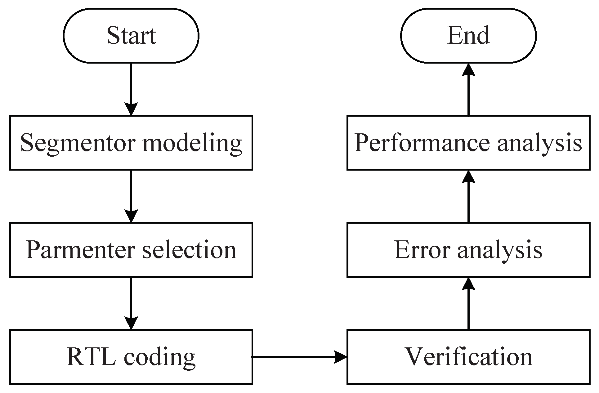
The design flow of the proposed approach is illustrated in Figure 7. Initially, the segmentor was modeled in MATLAB. Then, the five target nonlinear functions were divided by the segmentor with various values of sw. For each target function, the value of sw was determined by the relationship between sw and the number of segments. The values of kq, bq, sp and ep were then calculated by the segmentor with the determined value of sw. The register-transfer-level (RTL) implementation of the hardware circuit was coded in the Verilog HDL. Synopsys VCS was used to verify the Verilog code and to analyze the error of the designs. Finally, the designs were synthesized by the Synopsys Design Compiler with the cycle time as input and the area and power as outputs. The synthesized results were analyzed and compared.
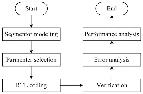
Figure 7.
Flowchart of the proposed approach.
4. Hardware Architecture
Based on the output of the proposed segmentor, we implemented hardware circuits for , , , and . The input width of the multiplier was reduced. Moreover, the Booth multiplier was used in the implementation. Based on the hardware circuit for a single function, a corresponding hardware architecture without the reuse of computing resources was implemented. Finally, reconfigurable technology was applied for multifunction implementation with the reuse of computing resources. The hardware architectures for single functions and multiple functions were modeled in Verilog, verified by Synopsys VCS (version 2016.06) and synthesized by the Synopsys Design Compiler (version 2016.03).
4.1. Single-Function Implementation
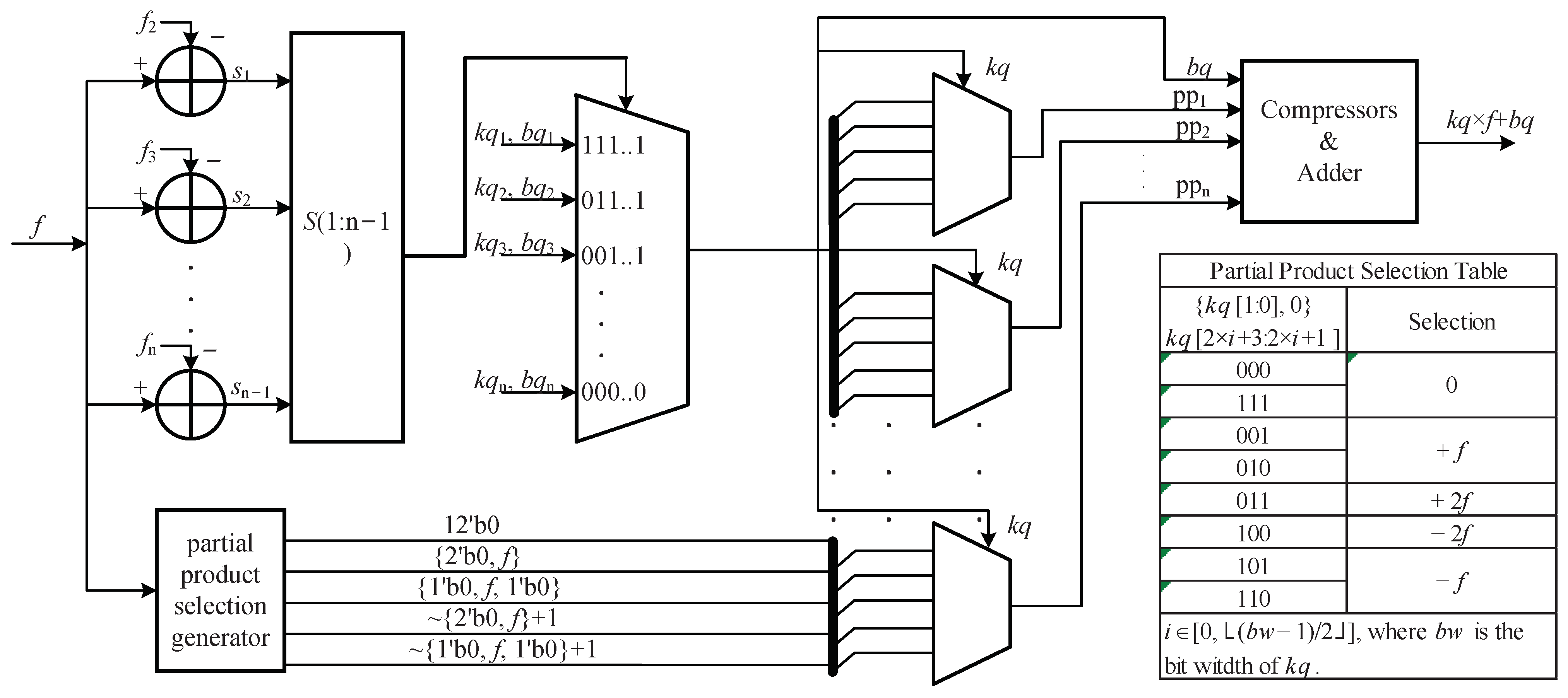
In the hardware architecture of [30], the multiplier has a large hardware overhead. We focus on our optimization of the multiplier. In our design, the Booth encoding of the multiplicand (kq) was used to reduce the number of partial products. Compressors were introduced to calculate the sum of the partial products. Additionally, the selections of kq and bq were performed in parallel with the preparation of the partial product selections for the multiplier.
The proposed architecture is illustrated in Figure 8. The mantissa part of an FP16 value, f, was provided as the input to the hardware architecture. After entering the circuit, f was operated on in two parallel branches. One branch determines the segment to which the input f belongs. The input f was compared against the starting points of the 2nd to nth segments, where n is the number of segments. Then, the concatenation of the signs of the outputs of all co-comparators served as the selection signal for the multiplexer to select the coefficients kq and bq of the linear function in the corresponding segment. The other branch generated the five possible selections for the partial products of the Booth multiplier. After the above parallel operations, the partial products were selected by the multiplexers with the three bits of kq, as shown in the partial product selection table presented in Figure 8. These partial product selections were also executed in parallel. The numbers of partial products are related to the bits of kq, as shown in Table 1. In addition, the first partial product was determined by the two least significant bits because the adding bit is always zero. Therefore, a 4:1 multiplexer was applied to obtain the first partial product. Furthermore, several 8:1 multiplexers were used to select the middle partial products. However, the last multiplexer for each function was distinctive in that it had the smallest possible hardware resource consumption. The last partial product of was selected by because the sign bits are always zero. Therefore, a 2:1 multiplexer was used to obtain the last partial product. Similarly, 2:1, 4:1, 2:1 and 4:1 multiplexers were used with , , and , respectively, as selection signals to obtain the last partial product in the hardware architectures of , , and , respectively.
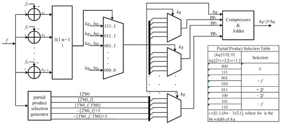
Figure 8.
Proposed hardware architecture for the implementation of a single function. The symbols , and represent the starting points of the 2nd, 3rd and segments, respectively. The symbols to denote the signs of the outputs of the comparators.
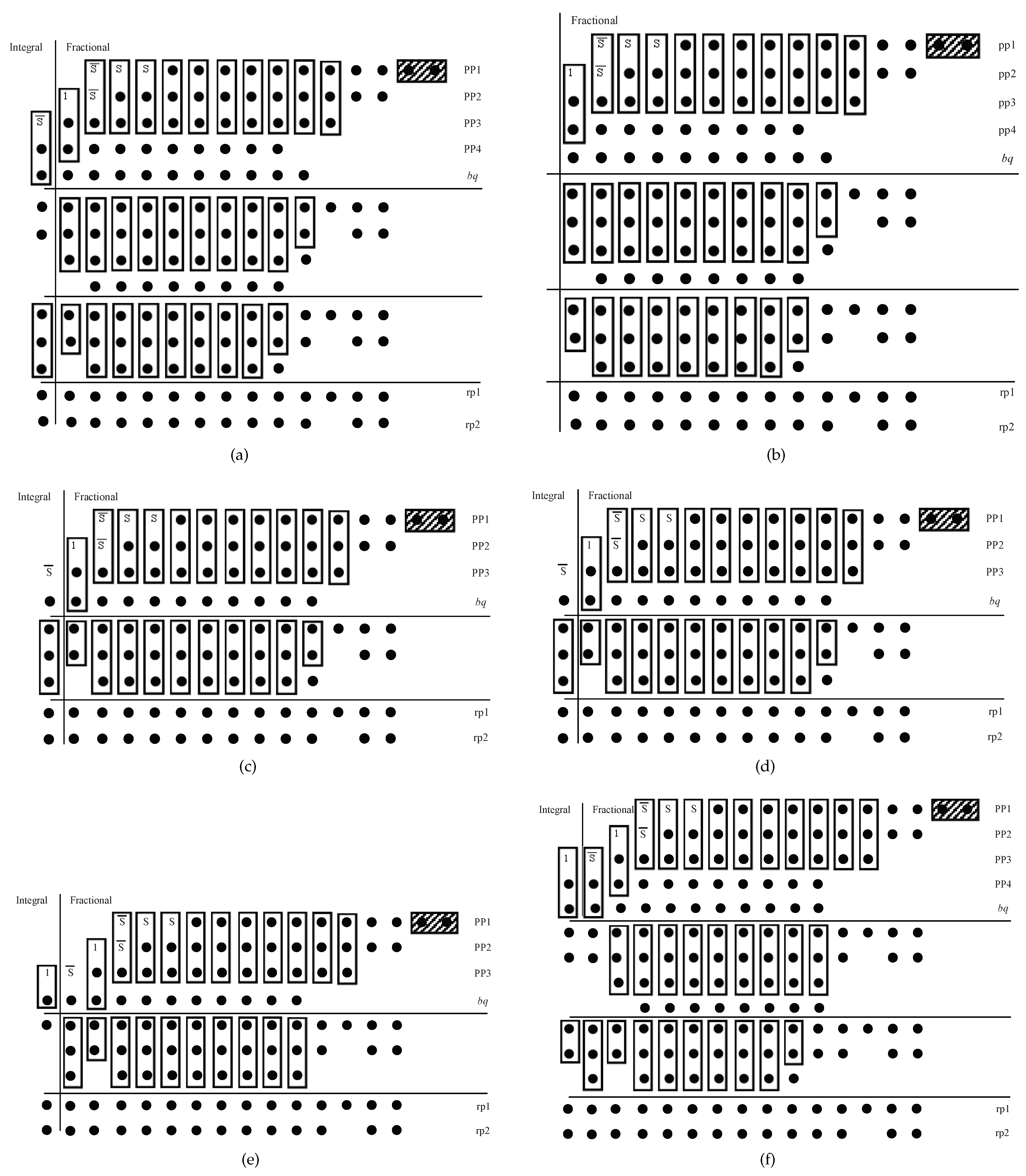
Then, our task was to obtain the sum of the partial products and bq. In our design, they were compressed to two results. The two results of the compressors were added by an adder. In the traditional Booth multiplier, the sign bits fill in the most significant bit (MSB) to ensure that the partial products are left-aligned. However, the filling with sign bits can be reduced by means of the sign extension method [37]. The compressor and adder implementations are related to the lengths of bq and the output, as shown in Table 2. The integral and fractional parts of the partial products and bq are aligned in Figure 9. In accordance with Figure 9a, the compressor in the circuit is illustrated in Figure 10. The sum of the partial products and bq is the result of this circuit, whose range and bits are shown in Table 2. The result for requires only 10 fractional bits. However, the two least significant bits (LSBs) of pp1 are not different from the preceding 10 fractional bits. Therefore, they were directly abandoned. In stage 0 of the compressor, only two inputs, pp1 and pp2, were involved. They were sent to rp1 and rp2 without any treatment, where rp1 and rp2 are the two outputs of the compressor. In stage 1, the three inputs, pp1, pp2 and pp3, were compressed into two results. A full adder can realize this task. In stage 2, the four inputs are pp1, pp2, pp3 and bq. A full adder and a half adder were used to compress these inputs into two results and a carry. In stage 3, pp1, pp2, pp3, pp4 bq and the carry in stage 2 were compressed into two results and two carries by two full adders and one half adder. In stage 4, three full adders were used to compress pp1, pp2, pp3, pp4, bq and the two carries into two results and two carries. Stages 5 to 10 have the same functions and units as stage 4. In stage 10, the 11th bit of the partial product is the sign bit, according to the symbol S in Figure 9. In stage 11, the number of inputs is decreased. Two full adders and one half adder were needed to implement a compressor with inputs consisting of 1, pp3, pp4, bq and the two carries from stage 10. In stage 12, pp3, pp4 bq and the two carries from stage 11 are the inputs. Two full adders were needed. Because only one integral bit is useful in the output, the high-order bits were abandoned. As seen from Figure 9a,b, the compressors for and have the same inputs. However, their outputs have different integral bits. Therefore, the integral bits of were directly abandoned. Hence, stage 12 for was omitted in the implementation for . As shown in Figure 9c,d, the compressors for and have the same inputs. Therefore, the hardware implementations of the compressors for and are the same as in Figure 11. As shown in Figure 12, the simple hardware implementation of the compressor for is a result of the reduced number of partial products compared with the other functions. Finally, an adder was used to compute the sum of the two compressor results. After truncating the result of the adder to 10 fractional bits, the output of the proposed circuit was obtained.

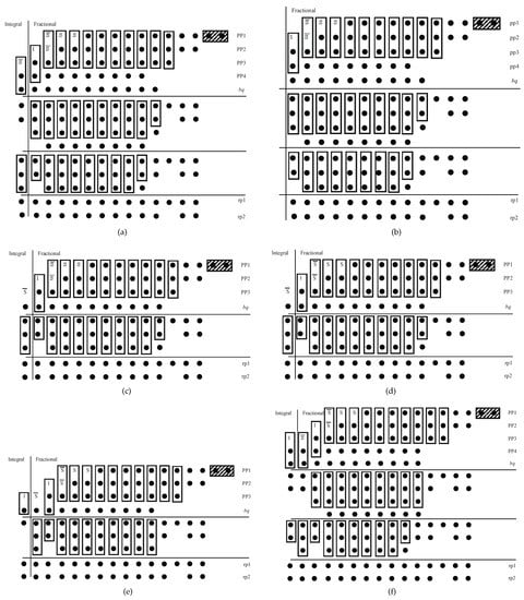
Figure 9.
Partial products with sign extensions and bq in the implementations for (a), (b), (c), (d), (e) and multiple functions with the reuse of computing resources (f). Rectangular boxes indicate full or half adders. Rectangular boxes with slashes indicate that the bits are abandoned. pp1 to pp5 represent the partial products of the Booth multiplier. S is the sign bit of the partial product.

Figure 10.
Compressor circuit used in the implementations of and . The symbols rp1 and rp2 are the two results of the compressor.

Figure 11.
Compressor circuit used in the implementations of and . The symbols rp1 and rp2 are the two results of the compressor.

Figure 12.
Compressor circuit used in the implementation of . The symbols rp1 and rp2 are the two results of the compressor.
4.2. Multifunction Implementation without Reuse of Computing Resources
The hardware architecture of a multifunction implementation that does not reuse computing resources was designed for a comparison with the architecture in which computing resources are reused. The input op was used to specify which function the circuit executes. The five values of op range from 000 to 100, corresponding to the functions , , , and , respectively. The input f was sent to the circuits for all five functions. However, the results of the different functions have various numbers of bits. To make the number of bits consistent, sign bits that are always zero were filled in before the MSB of each result to obtain 11-bit numbers. Then, the output was selected by a multiplexer with op as its selection signal.
In the architecture with no reuse of computing resources, the implementations of the needed functions were simply combined. As the number of functions increases, the area usage scales up accordingly. Moreover, the power correspondingly increases because the circuits for all functions are always working.
4.3. Multifunction Implementation with Reuse of Computing Resources
To reduce the area and power consumption and improve the calculation density, we introduced reconfigurable technology to reuse computing resources among different functions. For this purpose, the bit widths of the multiplications and additions for all functions must be unified. Therefore, all of the functions were segmented with the same sw. As shown in Figure 5, the number of segments greatly increases when sw is less than 6. Therefore, we set sw to 6 to divide the five functions into 57 segments. Based on the bit widths of kq, sw and the outputs shown in Table 1 and Table 2, the proposed multifunction architecture with the reuse of computing resources is illustrated in Figure 13. The starting points of all segments for each function were combined as to , where the first number in the braces indicates the number of the corresponding function. To unify the bits of to , n was set as equal to the largest number of segments among the five functions, which was 15 in our design. If the number of segments is fewer than 15, the significant bits are filled with the starting point of the last segment. The function selection code op was used to determine the starting points of the 2nd to nth segments for the corresponding function. Similar to the circuit in Figure 8, the input f and were compared by several adders. The signs of the comparators and op serve as the selection signals of the multiplexer to locate the inputs for the corresponding segments of the corresponding function. In addition, kq and bq were determined. The other parts of the multifunction architecture with the reuse of computing resources, as shown in Figure 13, are the same as those of the proposed architecture for single functions shown in Figure 8. Additionally, the Booth encoding method was used to generate the partial products in Figure 9f. In accordance with Figure 9f, the compressor is illustrated in Figure 14.

Figure 13.
Proposed hardware architecture of the single-function implementation. The symbols , and represent the starting points of the 2nd, 3rd and nth segments, respectively. The symbols to denote the signs of the outputs of the comparators.

Figure 14.
Compressor circuit used in the multifunction implementation with reuse of computing units. The symbols rp1 and rp2 are the two results of the compressor.
5. Implementation Results and Comparison
The proposed single-function and multifunction hardware architectures were coded in Verilog and synthesized by the Synopsys Design Compiler in TSMC 65-nm CMOS technology. In this section, the implementation results of the proposed architecture for a single function are compared with the hardware architecture in [30], as shown in Table 3. In addition, the results of the multifunction implementations with and without the reuse of computing resources are compared, as shown in Table 3. As shown in Table 3, all designs are of the same level of precision, with similar MAE values.

Table 3.
Application-specific integrated circuit (ASIC) implementation results of our design and the designs considered for comparison.
5.1. Results of Single-Function Architecture Implementation
(1) Timing Comparison:
The total delay in the proposed circuit architecture for is the sum of the delays in one comparator, one 15:1 multiplexer, one 8:1 multiplexer, three full adders and one 14-bit adder. Therefore, the maximum frequency is increased by 7.89% compared with [30].
The delay in the circuit for consists of the delays in one comparator, one 14:1 multiplexer, one 8:1 multiplexer, three full adders and one 13-bit adder. Compared with [30], our work improves the maximum frequency by 4.70%.
The total delay in the hardware architecture for includes the delays in one comparator, one 14:1 multiplexer, one 8:1 multiplexer, two full adders and one 14-bit adder. Our method improves the maximum frequency by 28.86% compared with [30].
The delay for involves the delays in one comparator, one 11:1 multiplexer, one 8:1 multiplexer, two full adders and one 14-bit adder. The maximum frequency is increased by 46.90% compared with [30].
The total delay in the circuit for comprises the delays in one comparator, one 7:1 multiplexer, one 8:1 multiplexer, two full adders and one 15-bit adder. The maximum frequency of our hardware circuit is improved by 34.78% compared with [30].
(2) Hardware Consumption Comparison:
As shown in Figure 8 and Figure 10, the entire hardware implementation of the proposed circuit uses fourteen comparators, one 15:1 multiplexer, two 12-bit adders in the partial product selection generator, one 4:1 multiplexer, two 8:1 multiplexers, one 2:1 multiplexer, twenty-nine full adders, three half adders and one 14-bit adder. As shown in Figure Table 3, our design costs 9.16% less area and 17.90% less power than [30]. With the traditional CORDIC approach, the natural logarithm and natural exponent can be directly calculated. However, an additional multiplier is essential for the computation of logarithmic and exponential functions with other bases, such as base 2. Generalized hyperbolic (GH) CORDIC has been proposed to calculate logarithms and exponents with arbitrary fixed bases [5]. The number of iterations and the fractional bit width were set to 10 and 13, respectively, to compute the exponential function with base 2. Because GH CORDIC in rotation mode (GHR CORDIC) was used, the fourth iteration was performed twice. Therefore, 11 iteration modules are needed. Before the output, an addition operation was used to obtain the sum of the two results of GHR CORDIC. There are 6 adders and 3 multiplexers in each iteration module. Therefore, a total of 67 adders and 33 multiplexers are needed in the overall architecture. In addition, each iteration requires 1 clock cycle, and an additional clock cycle is occupied by the adder before output. Thus, the total latency of the architecture in [5] is 12 clock cycles. Our design has a 93.65% delay improvement, a 79.94% area improvement and a 51.72% power improvement compared with the architecture in [5].
As shown in Figure 8 and Figure 10, there are thirteen comparators, one 14:1 multiplexer, two 12-bit adders, one 4:1 multiplexer, three 8:1 multiplexers, twenty-seven full adders, three half adders and one 13-bit adder in the proposed hardware implementation for . Compared with [30], our work achieves a 55.64% area reduction and a 54.85% power reduction. Based on GH CORDIC, [5,8] presented a transformed HV-CORDIC (THV-CORDIC) approach for calculating , where R is a floating-point number. THV-CORDIC is a special case of GH CORDIC in vector mode (GHV CORDIC) with base 2. The difference between the exponential function implementation and the logarithmic function computation is that a shifter instead of an adder is needed before the output. Therefore, the overall logarithm computation in [8] occupies 66 adders, 33 multiplexers and 1 shifter. Because the shifter before the output requires 1 clock cycle, the total number of clock cycles required by the hardware in [8] is 12. Our design reduces the delay by 93.33%, the area by 86.57% and the power by 72.29% compared with the design in [8].
As shown in Figure 8 and Figure 11, the proposed hardware circuit for occupies thirteen comparators, one 14:1 multiplexer, two 12-bit adders, one 4:1 multiplexer, two 8:1 multiplexers, nineteen full adders, three half adders and one 14-bit adder. Compared with the method in [30], our method consumes 34.38% less area and 28.64% less power. In [11], the NR method is used to implement the division and inverse square root functions. For comparison with our design, we reproduced the hardware architecture in [11] with the same bit width as in our design and an accuracy within 1 ulp. The division operation is based on reciprocals. The recursive equation for the reciprocal operation is , and it was used to calculate , where converges to after multiple iterations. To achieve an accuracy within 1 ulp, three iterations were executed with a fractional bit width of 12. As seen from the recursive equation, the multiplication operation was executed twice in each iteration. A fully pipelined architecture (one valid output per clock cycle) requires six multipliers and three adders. Each multiplier (with or without an adder) requires one clock cycle. Thus, this hardware implementation requires six clock cycles. Therefore, our design reduces the delay by 89.17%, the area by 85.04% and the power by 81.71% compared with the design in [11].
As shown in Figure 8 and Figure 11, there are ten comparators, one 11:1 multiplexer, two 12-bit adders, one 4:1 multiplexer, two 8:1 multiplexers, nineteen full adders, three half adders and one 14-bit adder in the proposed hardware architecture for . Compared with [30], our work improves the area consumption by 44.10% and the power consumption by 36.62%. Similar to the reciprocal method, is the recursive equation for the inverse square root function [11]. The number of iterations and the fractional bit width were set to 3 and 12, respectively. There are three multiplication operations in each iteration of the inverse square root calculation. The fully pipelined hardware architecture of [11] requires nine multipliers and three adders. In addition, the latency is nine clock cycles. Therefore, our design reduces the delay by 93.47%, the area by 90.49% and the power by 85.79% compared with the design in [11].
As shown in Figure 8 and Figure 12, the proposed hardware implementation for employs six comparators, one 7:1 multiplexer, two 12-bit adders, one 4:1 multiplexer, two 8:1 multiplexers, twenty full adders, two half adders and one 15-bit adder. Compared with [30], our method requires 47.77% less area and 43.59% less power. In [38], traditional hyperbolic CORDIC in vector mode (HV CORDIC) is used to implement the square root function. The number of iterations and the fractional bit width were set to 10 and 13, respectively. Similar to GHV CORDIC, the fourth iteration was executed twice. After all iterations, the result was multiplied by the reciprocal of the scale factor. Therefore, 66 adders, 33 multiplexers and 1 multiplier are needed in the whole architecture. The number of clock cycles required is 12. Accordingly, our design reduces the delay by 95.74%, the area by 86.39% and the power by 57.88% compared with the design in [38].
5.2. Results of Multifunction Architecture Implementation
Circuits for all five target functions are included in the multifunction hardware architecture with the reuse of computing resources. Additionally, one 5:1 multiplexer was added before the circuit output. However, the hardware overhead was reduced because of the reuse of computing units. The proposed hardware architecture in Figure 13 uses one 5:1 multiplexer, fourteen comparators, one 57:1 multiplexer, two 12-bit adders, one 4:1 multiplexer, three 8:1 multiplexers, twenty-nine full adders, three half adders and one 15-bit adder. As the implementation results in Table 3 show, the area and power consumption of the architecture with the reuse of computing units are reduced by 37.48% and 45.60%, respectively, at 1.25 GHz compared with the architecture without reuse.
We also used the PWL method in [30] to implement a reconfigurable architecture for multifunction evaluation with the reuse of computing units. As shown in Table 4, our design saves 9.2% area and 2.82% power at a higher frequency compared with the reconfigurable architecture for multifunction evaluation based on the PWL method in [30].

Table 4.
ASIC implementation results of designs for multifunction evaluation.
Moreover, the design presented in [39] is compatible with the computation of two functions. To compare our method with the design in [39], we introduce the area per function (APF) and the power per function (PPF) as two metrics to evaluate the area and power. The APF and PPF metrics are defined as
and
As shown in Table 4, the APF and PPF of our design are reduced by 55.75% and 65.26%, respectively, compared with the design in [39].
6. Conclusions
Based on an enhanced universal PWL method, this article proposes an area- and power-efficient reconfigurable architecture for multifunction evaluation by reusing computing resources among different functions.
The proposed segmentor unifies the fractional bit widths of b and to avoid truncation operations after the optimization of b. Only the fractional bit width of k was separately set. The proposed segmentor uses a smaller fractional bit width for k with a similar number of segments to achieve the same precision as the previous state-of-the-art segmentor. In the hardware architecture for a single function, the Booth encoding method was introduced to reduce the number of partial products. In addition, compressors were used to reduce the critical path. Compared with the state-of-the-art architecture in [30], our method is superior in terms of the delay, area and power for the implementation of five functions that are frequently used in computer graphics and DNNs.
We additionally implemented multifunction hardware architectures with and without the reuse of computing resources. Between the two, the implementation with resource reuse exhibits decisive advantages in the delay, area and power.
In this paper, we considered only computations on the fractional part of an FP16 value. In future work, we will implement the same five functions on the whole FP16 value by addressing computations on the exponential part. Moreover, we will apply the proposed hardware architecture for multifunction evaluation in a DNN chip or a graphics processing unit in ASIC technology.
Author Contributions
Conceptualization, S.Z. and G.Z.; methodology, S.Z. and Y.W. (Yu Wang); software, S.Z. and G.Z.; validation, S.Z.; investigation, S.Z. and F.L.; data curation, S.Z. and G.Z.; writing—original draft preparation, S.Z.; writing—review and editing, F.L., Y.W. (Yuxuan Wang), H.P. and Y.L.; supervision, F.L. and Y.L.; project administration, H.P.; funding acquisition, Y.W. (Yu Wang) and F.L. All authors have read and agreed to the published version of the manuscript.
Funding
This work was supported by the National Natural Science Foundation of China under Grant 62201234, the Natural Science Foundation of the Jiangsu Higher Education Institutions of China under Grant 21KJB510012, and the Scientific Research Foundation for the High-Level Talents of Jinling Institute of Technology under Grant jit-b-201907.
Data Availability Statement
Not applicable.
Conflicts of Interest
The authors declare no conflict of interest.
Abbreviations
The following abbreviations are used in this manuscript:
| MAE | Maximum absolute error |
| Predefined MAE in the segmentor | |
| MXE | Maximum error value |
| MIE | Minimum error value |
| MAE before optimization with the method in Section 2.2 | |
| MAE after optimization with the method in Section 2.2 | |
| k | Slope of the linear function |
| kq | Slope of the linear function after quantification |
| b | Y-intercept of the linear function |
| bq | Y-intercept of the linear function after quantification |
| sp | Starting point of the current segment |
| ep | Ending point of the current segment |
| lp | Leftmost point of the bisection window |
| rp | Rightmost point of the bisection window |
| leg | Number of inputs |
| qw | Fractional bit width of the intermediate data |
| sw | Fractional bit width of the slope |
| bw | Bit width of the slope (including integral and fractional parts) |
| iw | Fractional bit width of the inputs and outputs |
| PWL | Piecewise linear |
| FP16 | Half-precision floating-point format |
| ulp | Unit in the last place |
| DNNs | Deep neural networks |
| pp | Partial product |
| RTL | Register-transfer level |
| ASIC | Application-specific integrated circuit |
| NR | Newton–Raphson |
| HPA | High-degree polynomial approximation |
| APF | Area per function |
| PPF | Power per function |
References
- Harris, D. A powering unit for an OpenGL lighting engine. In Proceedings of the Conference Record of Thirty-Fifth Asilomar Conference on Signals, Systems and Computers (Cat.No.01CH37256), Pacific Grove, CA, USA, 4–7 November 2001; Volume 2, pp. 1641–1645. [Google Scholar] [CrossRef]
- Reuther, A.; Michaleas, P.; Jones, M.; Gadepally, V.; Samsi, S.; Kepner, J. Survey of Machine Learning Accelerators. In Proceedings of the 2020 IEEE High Performance Extreme Computing Conference (HPEC), Waltham, MA, USA, 22–24 September 2020; pp. 1–12. [Google Scholar] [CrossRef]
- Ellaithy, D.M.; El-Moursy, M.A.; Ibrahim, G.H.; Zaki, A.; Zekry, A. Double Logarithmic Arithmetic Technique for Low-Power 3-D Graphics Applications. IEEE Trans. Very Large Scale Integr. (VLSI) Syst. 2017, 25, 2144–2152. [Google Scholar] [CrossRef]
- Wang, Z.; Lin, J.; Wang, Z. Accelerating Recurrent Neural Networks: A Memory-Efficient Approach. IEEE Trans. Very Large Scale Integr. (VLSI) Syst. 2017, 25, 2763–2775. [Google Scholar] [CrossRef]
- Luo, Y.; Wang, Y.; Ha, Y.; Wang, Z.; Chen, S.; Pan, H. Generalized Hyperbolic CORDIC and Its Logarithmic and Exponential Computation with Arbitrary Fixed Base. IEEE Trans. Very Large Scale Integr. (VLSI) Syst. 2019, 27, 2156–2169. [Google Scholar] [CrossRef]
- Mopuri, S.; Acharyya, A. Low Complexity Generic VLSI Architecture Design Methodology for Nth Root and Nth Power Computations. IEEE Trans. Circuits Syst. I Regul. Pap. 2019, 66, 4673–4686. [Google Scholar] [CrossRef]
- Wang, Y.; Luo, Y.; Wang, Z.; Shen, Q.; Pan, H. GH CORDIC-Based Architecture for Computing N th Root of Single-Precision Floating-Point Number. IEEE Trans. Very Large Scale Integr. (VLSI) Syst. 2020, 28, 864–875. [Google Scholar] [CrossRef]
- Chen, H.; Cheng, K.; Lu, Z.; Fu, Y.; Li, L. Hyperbolic CORDIC-Based Architecture for Computing Logarithm and Its Implementation. IEEE Trans. Circuits Syst. II Express Briefs 2020, 67, 2652–2656. [Google Scholar] [CrossRef]
- Wu, R.; Chen, H.; He, G.; Fu, Y.; Li, L. Low-Latency Low-Complexity Method and Architecture for Computing Arbitrary Nth Root of Complex Numbers. IEEE Trans. Circuits Syst. I Regul. Pap. 2022, 69, 2529–2541. [Google Scholar] [CrossRef]
- Kornerup, P.; Muller, J.M. Choosing starting values for certain Newton–Raphson iterations. Theor. Comput. Sci. 2006, 351, 101–110. [Google Scholar] [CrossRef]
- Aslan, S.; Oruklu, E.; Saniie, J. Realization of area efficient QR factorization using unified division, square root, and inverse square root hardware. In Proceedings of the 2009 IEEE International Conference on Electro/Information Technology, Windsor, ON, Canada, 7–9 June 2009; pp. 245–250. [Google Scholar] [CrossRef]
- Vestias, M.P.; Neto, H.C. Revisiting the Newton-Raphson Iterative Method for Decimal Division. In Proceedings of the 2011 21st International Conference on Field Programmable Logic and Applications, Chania, Greece, 5–7 September 2011; pp. 138–143. [Google Scholar] [CrossRef]
- Rodriguez-Garcia, A.; Pizano-Escalante, L.; Parra-Michel, R.; Longoria-Gandara, O.; Cortez, J. Fast fixed-point divider based on Newton-Raphson method and piecewise polynomial approximation. In Proceedings of the 2013 International Conference on Reconfigurable Computing and FPGAs (ReConFig), Cancun, Mexico, 9–11 December 2013; pp. 1–6. [Google Scholar] [CrossRef]
- Jain, R.; Pandey, N. Realization of Regula-Falsi Iteration based Double Precision Floating Point Division. In Proceedings of the 2020 4th International Conference on Trends in Electronics and Informatics (ICOEI)(48184), Tirunelveli, India, 15–17 June 2020; pp. 88–92. [Google Scholar] [CrossRef]
- de Dinechin, F.; Tisserand, A. Multipartite table methods. IEEE Trans. Comput. 2005, 54, 319–330. [Google Scholar] [CrossRef]
- De Caro, D.; Petra, N.; Strollo, A.G.M. Reducing Lookup-Table Size in Direct Digital Frequency Synthesizers Using Optimized Multipartite Table Method. IEEE Trans. Circuits Syst. I Regul. Pap. 2008, 55, 2116–2127. [Google Scholar] [CrossRef]
- Low, J.Y.L.; Jong, C.C. A Memory-Efficient Tables-and-Additions Method for Accurate Computation of Elementary Functions. IEEE Trans. Comput. 2013, 62, 858–872. [Google Scholar] [CrossRef]
- Hsiao, S.F.; Wu, P.H.; Wen, C.S.; Meher, P.K. Table Size Reduction Methods for Faithfully Rounded Lookup-Table-Based Multiplierless Function Evaluation. IEEE Trans. Circuits Syst. II Express Briefs 2015, 62, 466–470. [Google Scholar] [CrossRef]
- Hsiao, S.F.; Wen, C.S.; Chen, Y.H.; Huang, K.C. Hierarchical Multipartite Function Evaluation. IEEE Trans. Comput. 2017, 66, 89–99. [Google Scholar] [CrossRef]
- Chen, H.; Yang, H.; Song, W.; Lu, Z.; Fu, Y.; Li, L.; Yu, Z. Symmetric-Mapping LUT-Based Method and Architecture for Computing XY-Like Functions. IEEE Trans. Circuits Syst. I: Regul. Pap. 2021, 68, 1231–1244. [Google Scholar] [CrossRef]
- Lee, D.U.; Cheung, R.; Luk, W.; Villasenor, J. Hardware Implementation Trade-Offs of Polynomial Approximations and Interpolations. IEEE Trans. Comput. 2008, 57, 686–701. [Google Scholar] [CrossRef]
- Strollo, A.G.; De Caro, D.; Petra, N. Elementary Functions Hardware Implementation Using Constrained Piecewise-Polynomial Approximations. IEEE Trans. Comput. 2011, 60, 418–432. [Google Scholar] [CrossRef]
- De Caro, D.; Napoli, E.; Esposito, D.; Castellano, G.; Petra, N.; Strollo, A.G.M. Minimizing Coefficients Wordlength for Piecewise-Polynomial Hardware Function Evaluation With Exact or Faithful Rounding. IEEE Trans. Circuits Syst. I Regul. Pap. 2017, 64, 1187–1200. [Google Scholar] [CrossRef]
- Ellaithy, D.M.; El-Moursy, M.A.; Zaki, A.; Zekry, A. Dual-Channel Multiplier for Piecewise-Polynomial Function Evaluation for Low-Power 3-D Graphics. IEEE Trans. Very Large Scale Integr. (VLSI) Syst. 2019, 27, 790–798. [Google Scholar] [CrossRef]
- An, M.; Luo, Y.; Zheng, M.; Wang, Y.; Dong, H.; Wang, Z.; Peng, C.; Pan, H. Piecewise Parabolic Approximate Computation Based on an Error-Flattened Segmenter and a Novel Quantizer. Electronics 2021, 10, 2704. [Google Scholar] [CrossRef]
- Liu, C.W.; Ou, S.H.; Chang, K.C.; Lin, T.C.; Chen, S.K. A Low-Error, Cost-Efficient Design Procedure for Evaluating Logarithms to Be Used in a Logarithmic Arithmetic Processor. IEEE Trans. Comput. 2016, 65, 1158–1164. [Google Scholar] [CrossRef]
- Loukrakpam, M.; Choudhury, M. Error-aware design procedure to implement hardware-efficient antilogarithmic converters. Circuits Syst. Signal Process. 2019, 38, 4266–4279. [Google Scholar] [CrossRef]
- Sun, H.; Luo, Y.; Ha, Y.; Shi, Y.; Gao, Y.; Shen, Q.; Pan, H. A Universal Method of Linear Approximation With Controllable Error for the Efficient Implementation of Transcendental Functions. IEEE Trans. Circuits Syst. I Regul. Pap. 2020, 67, 177–188. [Google Scholar] [CrossRef]
- Dong, H.; Wang, M.; Luo, Y.; Zheng, M.; An, M.; Ha, Y.; Pan, H. PLAC: Piecewise Linear Approximation Computation for All Nonlinear Unary Functions. IEEE Trans. Very Large Scale Integr. (VLSI) Syst. 2020, 28, 2014–2027. [Google Scholar] [CrossRef]
- Lyu, F.; Mao, Z.; Zhang, J.; Wang, Y.; Luo, Y. PWL-Based Architecture for the Logarithmic Computation of Floating-Point Numbers. IEEE Trans. Very Large Scale Integr. (VLSI) Syst. 2021, 29, 1470–1474. [Google Scholar] [CrossRef]
- Liu, W.; Liao, Q.; Qiao, F.; Xia, W.; Wang, C.; Lombardi, F. Approximate Designs for Fast Fourier Transform (FFT) With Application to Speech Recognition. IEEE Trans. Circuits Syst. I Regul. Pap. 2019, 66, 4727–4739. [Google Scholar] [CrossRef]
- Mittal, S. A survey of techniques for approximate computing. ACM Comput. Surv. (CSUR) 2016, 48, 1–33. [Google Scholar] [CrossRef]
- Lyu, F.; Xu, X.; Wang, Y.; Luo, Y.; Wang, Y.; Pan, H. Ultralow-Latency VLSI Architecture Based on a Linear Approximation Method for Computing Nth Roots of Floating-Point Numbers. IEEE Trans. Circuits Syst. I Regul. Pap. 2021, 68, 715–727. [Google Scholar] [CrossRef]
- Goldberg, D. What every computer scientist should know about floating-point arithmetic. ACM Comput. Surv. (CSUR) 1991, 23, 5–48. [Google Scholar] [CrossRef]
- Shukla, S.; Fleischer, B.; Ziegler, M.; Silberman, J.; Oh, J.; Srinivasan, V.; Choi, J.; Mueller, S.; Agrawal, A.; Babinsky, T.; et al. A Scalable Multi-TeraOPS Core for AI Training and Inference. IEEE Solid-State Circuits Lett. 2018, 1, 217–220. [Google Scholar] [CrossRef]
- Choi, S.; Sim, J.; Kang, M.; Choi, Y.; Kim, H.; Kim, L.S. An Energy-Efficient Deep Convolutional Neural Network Training Accelerator for In Situ Personalization on Smart Devices. IEEE J. Solid-State Circuits 2020, 55, 2691–2702. [Google Scholar] [CrossRef]
- Kuang, S.R.; Wang, J.P.; Guo, C.Y. Modified booth multipliers with a regular partial product array. IEEE Trans. Circuits Syst. II Express Briefs 2009, 56, 404–408. [Google Scholar] [CrossRef]
- Li, B.; Fang, L.; Xie, Y.; Chen, H.; Chen, L. A unified reconfigurable floating-point arithmetic architecture based on CORDIC algorithm. In Proceedings of the 2017 International Conference on Field Programmable Technology (ICFPT), Melbourne, Australia, 11–13 December 2017; pp. 301–302. [Google Scholar] [CrossRef]
- Chen, H.; Jiang, L.; Yang, H.; Lu, Z.; Fu, Y.; Li, L.; Yu, Z. An Efficient Hardware Architecture with Adjustable Precision and Extensible Range to Implement Sigmoid and Tanh Functions. Electronics 2020, 9, 1739. [Google Scholar] [CrossRef]
Publisher’s Note: MDPI stays neutral with regard to jurisdictional claims in published maps and institutional affiliations. |
© 2022 by the authors. Licensee MDPI, Basel, Switzerland. This article is an open access article distributed under the terms and conditions of the Creative Commons Attribution (CC BY) license (https://creativecommons.org/licenses/by/4.0/).

