
Design and Optimization of a Resonant Micro-Optic Gyroscope Based on a Transmissive Silica Waveguide Resonator


Abstract
1. Introduction
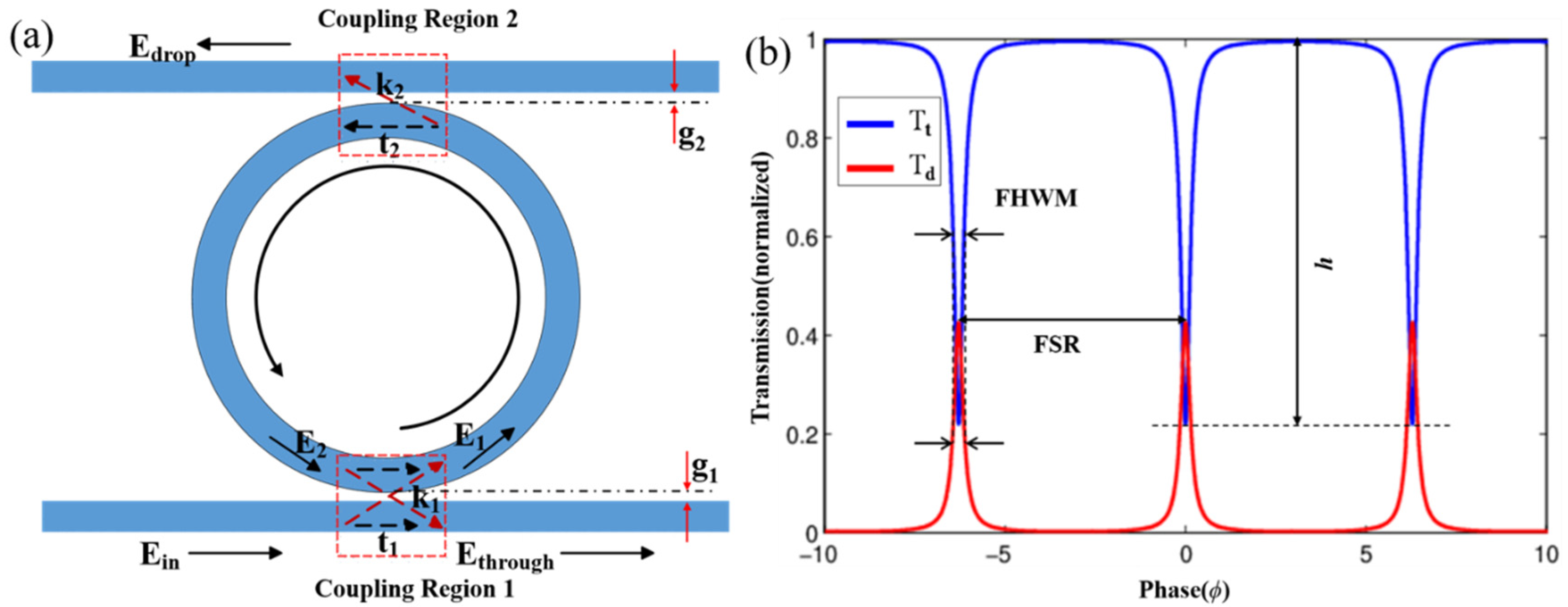
2. Principle and Simulation
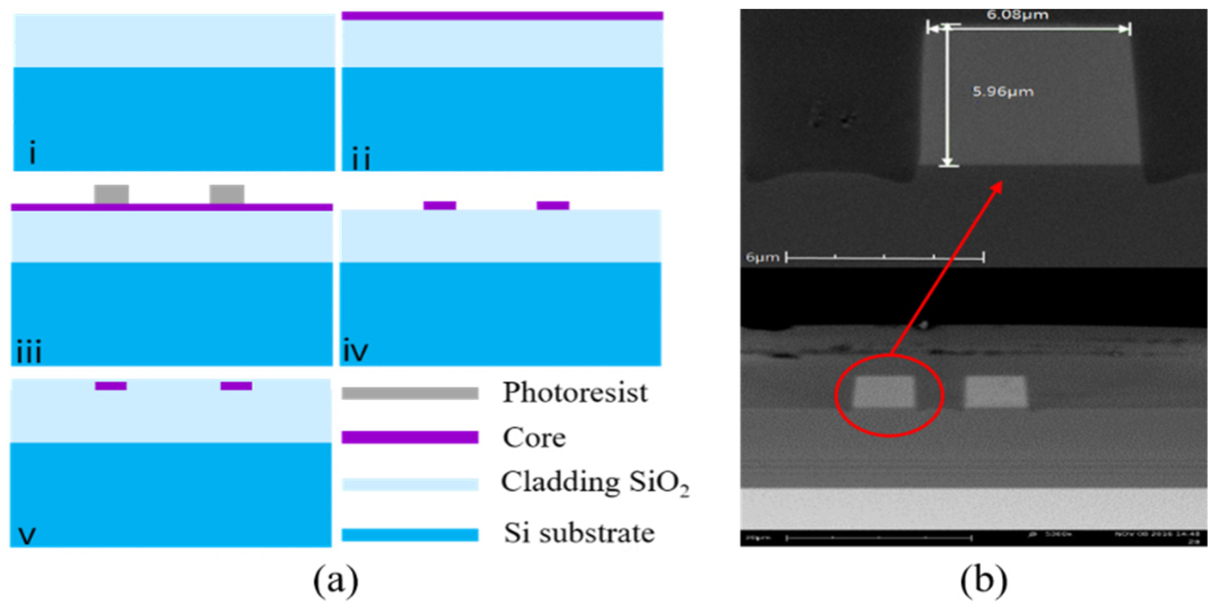
3. Design and Fabrication
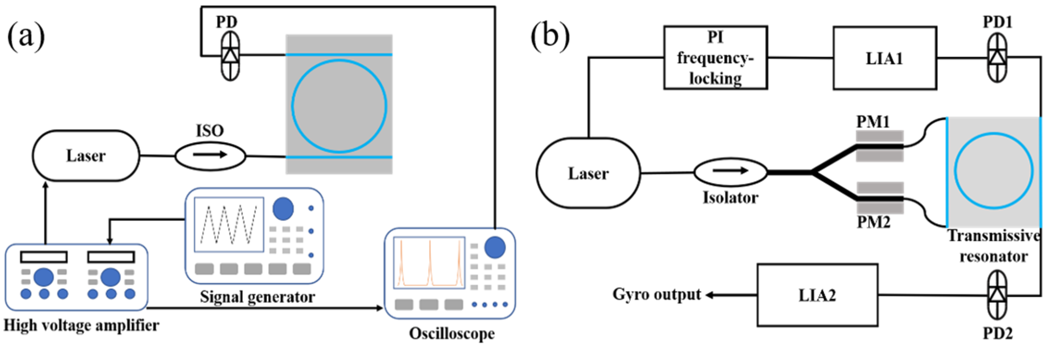
4. Experiment
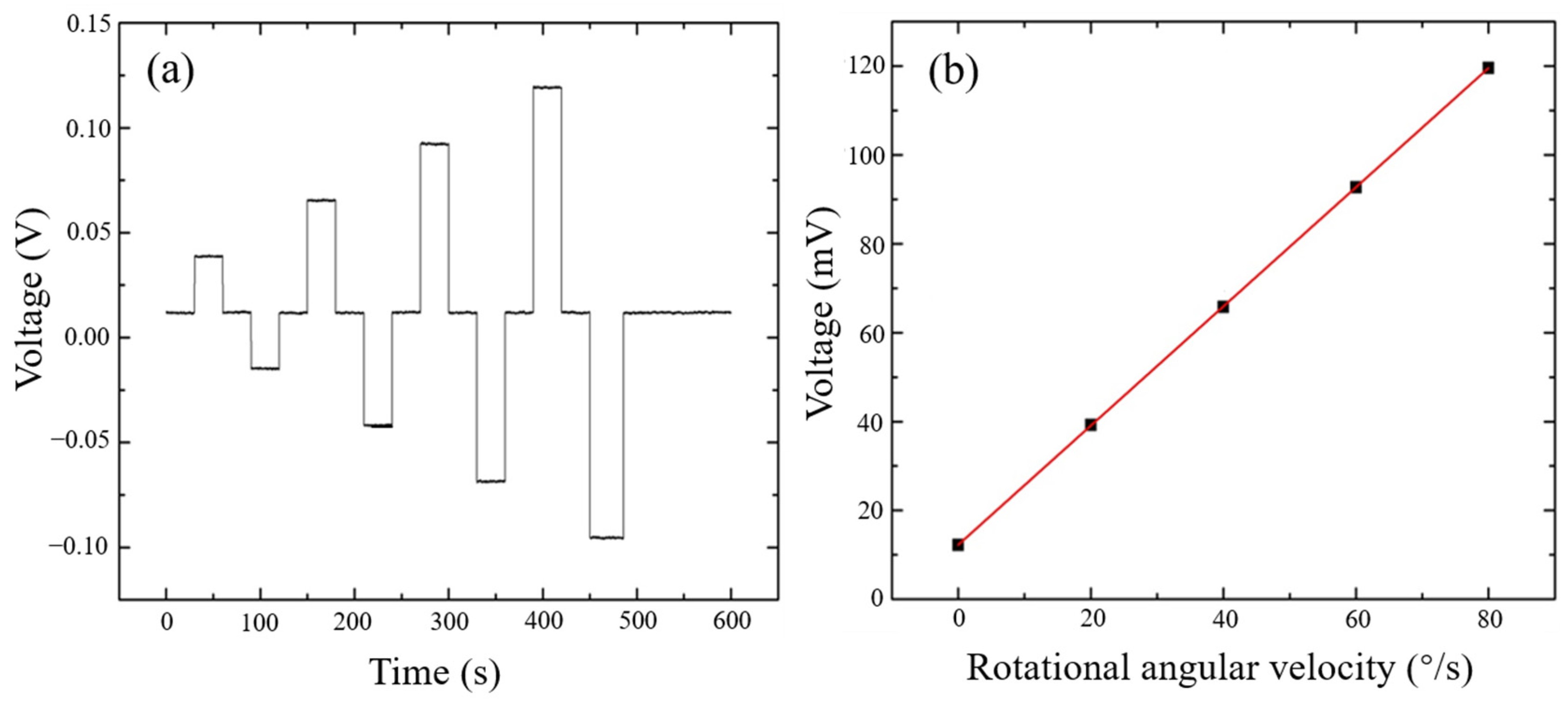
5. Results
6. Conclusions
Author Contributions
Funding
Conflicts of Interest
References
- Ciminelli, C.; Dell’Olio, F.; Campanella, C.; Armenise, M.N. Photonic technologies for angular velocity sensing. Adv. Opt. Photon. 2012, 2, 370–404. [Google Scholar] [CrossRef]
- Dell’Olio, F.; Indiveri, F.; Innone, F.; Russo, P.D.; Ciminelli, C.; Armenise, M. System test of an optoelectronic gyroscope based on a high Q-factor InP ring resonator. Opt. Eng. 2014, 53, 127104. [Google Scholar] [CrossRef]
- Guillén-Torres, M.; Cretu, E.; Jaeger, N.A.F.; Chrostowski, L. Ring resonator optical gyroscopes-parameter optimization and robustness analysis. J. Light. Technol. 2012, 30, 1802–1817. [Google Scholar] [CrossRef]
- Kalantarov, D.; Search, C.P. Effect of input–output coupling on the sensitivity of coupled resonator optical waveguide gyroscopes. J. Opt. Soc. Am. B 2013, 30, 377–381. [Google Scholar] [CrossRef]
- Ma, H.; Zhang, J.; Wang, L.; Lu, Y.; Ying, D.; Jin, Z. Resonant micro-optic gyro using a short and high-finesse fiber ring resonator. Opt. Lett. 2015, 40, 5862–5865. [Google Scholar] [CrossRef] [PubMed]
- Jin, Z.; Zhang, G.; Mao, H.; Ma, H. Resonator micro optic gyro with double phase modulation techniqueusing an FPGA-based digital processor. Opt. Commun. 2012, 285, 645–649. [Google Scholar] [CrossRef]
- An, P.; Zheng, Y.; Yan, S.; Xue, C.; Wang, W.; Liu, J. High-Q microsphere resonators for angular velocity sensing in gyroscopes. Appl. Phys. Lett. 2015, 106, 327. [Google Scholar] [CrossRef]
- Wang, J.; Feng, L.; Wang, Q. Reduction of angle random walk by in-phase triangular phase modulation technique for resonator integrated optic gyro. Opt. Express 2016, 24, 5463–5468. [Google Scholar] [CrossRef] [PubMed]
- Mao, H.; Ma, H.; Jin, Z. Polarization maintaining silica waveguide resonator optic gyro using double phase modulation technique. Opt. Express 2011, 19, 4632–4643. [Google Scholar] [CrossRef] [PubMed]
- Dell’Olio, F.; Conteduca, D.; Ciminelli, C.; Armenise, M.N. New ultrasensitive resonant photonic platform for label-free biosensing. Opt. Express 2015, 23, 28593–28604. [Google Scholar] [CrossRef] [PubMed]
- Chang, X.; Ma, H.; Jin, Z. Resonance asymmetry phenomenon in waveguide-type optical ring resonator gyro. Opt. Commun. 2012, 285, 1134–1139. [Google Scholar] [CrossRef]
- Spencer, D.T.; Bauters, J.F.; Heck, M.J.R.; Bowers, J.E. Integrated waveguide coupled Si3N4 resonators in the ultrahigh-Q regime. Optica 2014, 1, 153–157. [Google Scholar] [CrossRef]
- Qian, K.; Tang, J.; Guo, H.; Liu, W.; Liu, J.; Xue, C.; Zheng, Y.; Zhang, C. Under-coupling whispering gallery mode resonator applied to resonant micro-optic gyroscope. Sensors 2017, 17, 100. [Google Scholar] [CrossRef] [PubMed]
- Vannahme, C.; Suche, H.; Reza, S. Integrated optical Ti:LiNbO3 ring resonator for rotation rate sensing. In Proceedings of the 13th European Conference on Integrated Optics (ECIO), Copenhagen, Denmark, 25–27 April 2007. [Google Scholar]
- Ciminell, C.; D’Agostino, D.; Carnicella, G.; Dell’Olio, F.; Conteduca, D.; Ambrosius, H.P.M.M.; Smit, M.K.; Armenise, M.N. A high-Q InP resonant angular velocity sensor for a monolithically integrated optical gyroscope. IEEE Photon. J. 2015, 8, 6800418. [Google Scholar] [CrossRef]
- Wang, J.; Feng, L.; Wang, Q.; Jiao, H.; Wang, X. Suppression of backreflection error in resonator integrated optic gyro by the phase difference traversal method. Opt. Lett. 2016, 41, 1586–1589. [Google Scholar] [CrossRef] [PubMed]
- Haavisto, J.; Pajer, G.A. Resonance effects in low-loss ring waveguides. Opt. Lett. 1980, 5, 510–512. [Google Scholar] [CrossRef] [PubMed]
- Ma, H.; Chen, Z.; Yang, Z.; Yu, X.; Jin, Z. Polarization-induced noise in resonator fiber optic gyro. Appl. Opt. 2012, 51, 6708–6717. [Google Scholar] [CrossRef] [PubMed]
- Feng, L.; Wang, J.; Zhi, Y.; Tang, Y.; Wang, Q.; Li, H.; Wang, W. Transmissive resonator optic gyro based on silica waveguide ring resonator. Opt. Express 2014, 22, 27565–27575. [Google Scholar] [CrossRef] [PubMed]
- Poon, J.K.S.; Scheuer, J.; Mookherjea, S.; Paloczi, G.T.; Huang, Y.; Yariv, A. Matrix analysis of microring coupled-resonator optical waveguides. Opt. Express 2004, 12, 90–103. [Google Scholar] [CrossRef] [PubMed]
- Ying, D.; Wang, Z.; Mao, J.; Jin, Z. An open-loop RFOG based on harmonic division technique to suppress LD’s intensity modulation noise. Opt. Commun. 2016, 378, 10–15. [Google Scholar] [CrossRef]
- Matejček, M.; Šostronek, M. New experience with Allan variance: Noise analysis of accelerometers. In Proceedings of the Communication and Information Technologies (KIT), Vysoke Tatry, Slovakia, 4–6 October 2017; pp. 1–4. [Google Scholar]


| g1 (μm) | g2 (μm) | Quality Factor | Scale Factor (mV/°/s) |
|---|---|---|---|
| 6.9 | 6.7 | 2.1 × 10⁷ | 1.34 |
| 6.9 | 6.9 | 1.5 × 10⁷ | 0.79 |
| 6.7 | 6.7 | 1.2 × 10⁷ | 0.69 |
Publisher’s Note: MDPI stays neutral with regard to jurisdictional claims in published maps and institutional affiliations. |
© 2022 by the authors. Licensee MDPI, Basel, Switzerland. This article is an open access article distributed under the terms and conditions of the Creative Commons Attribution (CC BY) license (https://creativecommons.org/licenses/by/4.0/).
Share and Cite
Zhang, W.; Liu, W.; Guo, H.; Tang, J.; Liu, J. Design and Optimization of a Resonant Micro-Optic Gyroscope Based on a Transmissive Silica Waveguide Resonator. Electronics 2022, 11, 3355. https://doi.org/10.3390/electronics11203355
Zhang W, Liu W, Guo H, Tang J, Liu J. Design and Optimization of a Resonant Micro-Optic Gyroscope Based on a Transmissive Silica Waveguide Resonator. Electronics. 2022; 11(20):3355. https://doi.org/10.3390/electronics11203355
Chicago/Turabian StyleZhang, Wei, Wenyao Liu, Huiting Guo, Jun Tang, and Jun Liu. 2022. "Design and Optimization of a Resonant Micro-Optic Gyroscope Based on a Transmissive Silica Waveguide Resonator" Electronics 11, no. 20: 3355. https://doi.org/10.3390/electronics11203355
APA StyleZhang, W., Liu, W., Guo, H., Tang, J., & Liu, J. (2022). Design and Optimization of a Resonant Micro-Optic Gyroscope Based on a Transmissive Silica Waveguide Resonator. Electronics, 11(20), 3355. https://doi.org/10.3390/electronics11203355