Article

Stability Analysis and Robust Control Method for LCL-Type Three-Phase Four-Wire Split Capacitor Inverter Considering Zero-Sequence Loop

1
School of Electrical Engineering, China University of Mining and Technology, Xuzhou 221116, China
2
School of Intelligent Manufacturing, Jiangsu Vocational Institute of Architectural Technology, Xuzhou 221116, China
3
School of Electrical Engineering, Shenyang University of Technology, Shenyang 110027, China
*
Authors to whom correspondence should be addressed.
Electronics 2022, 11(20), 3286; https://doi.org/10.3390/electronics11203286
Submission received: 19 September 2022 / Revised: 7 October 2022 / Accepted: 9 October 2022 / Published: 12 October 2022
(This article belongs to the Special Issue Application of Power Electronics Technology in Energy System)

Abstract

:
In distributed generation systems, the inverter is the main power interface and its stability directly determines the reliable operation of the grid-connected system. As a typical topology for a three-phase four-wire inverter, the LCL-type three-phase four-wire split capacitor inverter (LCL-TFSCI) is taken as the research subject of this paper. Compared with the three-phase three-wire inverter, there is an additional zero-sequence path in the LCL-TFSCI. Therefore, it is not only necessary to consider the stability of the positive and negative sequence system, but there is also the need to consider the stability of the zero-sequence system when performing stability analysis for the LCL-TFSCI. In this paper, a small-signal impedance model considering the zero-sequence loop of LCL-TFSCI is firstly established. Subsequently, the instability risk is revealed when LCL-TFSCI is connected to the grid with parallel compensation capacitors. Through instability analysis, an impedance-reshaping method based on the complex filter and combined differential elements is proposed, which can reshape the impedance characteristic of LCL-TFSCI within the wide frequency range and expand the stability domain of the grid-connected system. Finally, the proposed method is verified by simulation and experiment.

1. Introduction

The grid-connected inverter functions as the power interface between distributed energy and power grid, the performance of which tends to have a significant impact on the power quality of system input to the power grid [1]. Featuring a zero-sequence current path, the three-phase four-wire inverter plays a vital role in compensating for load reactive current and balancing three-phase active current, which makes it widely applicable in engineering [2,3]. Its specific application areas include islanded microgrids [4], active filters [5], power redistribution devices [6], renewable energy power generation systems [7], uninterruptible power supplies [8], and power distribution systems [9]. However, as the new energy-penetration rate increases progressively, the power grid increasingly exhibits the characteristic of the weak power grid due to long transmission lines and the leakage inductance of transformers in the distribution network [10,11,12]. Meanwhile, measures such as adding parallel compensation capacitors are often adopted to improve power quality while mitigating line loss. According to the current studies, the coupling effect between the inverter and the grid with parallel compensation capacitors makes the system susceptible to high-frequency resonance and harmonic instability [13,14,15].
In order to solve the above problems, scholars worldwide have conducted some research on the instability mechanism of the inverter and the method of oscillation suppression. In [16], with the DC voltage-control loop of the inverter ignored, the mechanism of oscillation instability is revealed by introducing the power loop into mathematical derivation and analyzing the positive and negative characteristics of resistance. In [17], the high-frequency output impedance model of the inverter is reshaped by introducing differential components and Chebyshev filters into the control loop of the converter, which improves the stability margin in the context of the grid with parallel compensation capacitors. In [18], a series-lead compensator is adopted to weaken the negative phase shift introduced by an oscillation controller. However, this method has a small improvement in the stability margin of the inverter. In [19,20,21], an adaptive parameter optimization method of the current controller is proposed based on the real-time impedance measurement of the power grid, which enhances the robustness of the system to the changes in grid impedance. However, this control algorithm is more complex, which places a demanding requirement on the accuracy of grid impedance detection.
In addition, the PI controller in the PLL introduces the angular deviation into the control system of the inverter in the case of small-signal perturbation. At this time, the control d-q frame of the inverter no longer overlaps with the system d-q frame [22,23], which increases the difficulty of performing modeling and stability analysis for the inverter [24]. In the meantime, the coupling degree of PLL and inverter current loop is further increased in the weak grid, which increases the complexity of the control loop [25,26]. To solve this problem, it is proposed by some scholars to add a virtual controller [27] and impedance controller [28] into the output impedance of the inverter. In [29], the harmonic linearization method is adopted to build the positive and negative sequence impedance model of inverter, which considers the impact of PLL. However, this modeling method requires a large amount of computing workload. In [30], the impact of PLL on the stability of three-phase four-leg grid-connected inverter is considered for modeling. Differently, a single L-type filter is selected in this study and the impact of parallel compensation capacitors is ignored to reduce the difficulty of stability analysis. However, the equivalent impedance order of the grid is increased by the addition of grid-side parallel capacitors in the weak grid, which increases the difficulty in analyzing system stability [31].
From the above analysis, an overview of the current research on inverter stability improvement methods can be summarized as shown in Table 1. Most oscillation-suppression methods are applicable to three-phase three-wire inverters, which fail to take into account the stability of the zero-sequence loop. However, the conclusion of the stability analysis obtained with the neglect of the zero-sequence loop cannot fully and accurately reflect the system characteristics. Meanwhile, there is less research on wide-band oscillation-suppression methods for three-phase four-wire inverters considering zero-sequence loops. The LCL-TFSCI features a three-bridge arm structure, which has the advantages of having better compensation and low cost. Therefore, it has received attention from scholars worldwide and relevant research has been conducted recently. In view of the above analysis, a small-signal perturbation-modeling method for LCL-TFSCI based on the impedance model is proposed in this paper. Furthermore, the vector condition of the ideal reshaping impedance is derived by stability-domain analysis, and an oscillation-suppression method based on complex filters and combined differential elements is proposed. The main work and contributions of this paper can be summarized as follows:
(1) Considering the dynamic characteristic of PLL, an interaction relation with a dual d-q-0 frame is established, which is introduced into the inverter-current loop in the form of small-signal perturbation variables. A small-signal correlation impedance model is proposed. Since the proposed model considers the zero-sequence perturbation loop, the matrix dimension of the impedance model increases from 2D to 3D, which improves the accuracy of impedance modeling and stability analysis for LCL-TFSCI in the small-signal perturbation state.
(2) An oscillation-suppression method based on the complex filter and combined differential elements is proposed. It can simultaneously reshape the positive-sequence, negative-sequence, and zero-sequence impedance of the inverter within a wide frequency range, while the existing control strategies mainly focus on the resonant frequency point. The proposed method expands the region of stable operation for the inverter, which can avoid the frequency detection and improve the adaptability of LCL-TFSCI to changes of grid parameters.
The rest of this paper is organized as follows. In Section 2, the impedance model of LCL-TFSCI is deduced. Subsequently, the instability risk of the positive sequence, negative sequence, and zero sequence of the inverter is analyzed under the context of the grid with parallel compensation capacitors in Section 3. In Section 4, a method of oscillation suppression based on a complex filter and combined differential elements is proposed. Moreover, the proposed method of oscillation suppression for LCL-TFSCI is verified through simulation and experimentation in Section 5. Finally, the conclusions are drawn in Section 6.

2. Mathematical Modeling of LCL-TFSCI

2.1. Small-Signal Mathematical Modeling of the Inverter under Multiple Perturbation

When there is small-signal perturbation component in the interconnected system between an LCL-TFSCI and power grid, the control d-q frame and the system d-q frame no longer overlap. In this case, the traditional impedance-modeling method cannot precisely reflect the output characteristic of the inverter impedance, which in turn affects the correctness of the system-stability-analysis results. In order to accurately reflect the output characteristic of the inverter impedance and facilitate the subsequent analysis of the oscillation-suppression method for LCL-TFSCI, a small-signal model of LCL-TFSCI will be deduced under multiple perturbation in this section. Figure 1 shows the equivalent control diagram of LCL-TFSCI connected to the grid. In this figure, Gi(s) denotes PI current controller; L1 denotes the inverter-side inductance; L2 denotes the grid-side inductance; C denotes filter capacitor; Ln denotes the mid-line inductance; and ea, eb, ec denote the three-phase equivalent voltage source of the grid, respectively.
To deduce the equivalent impedance of LCL-TFSCI, a small-signal mathematical model of the inverter is established as follows. According to Figure 1, the Kirchhoff voltage equation for the control loop of the inverter side can be expressed as:
[ u a n u b n u c n ] = [ L 1 0 0 0 L 1 0 0 0 L 1 ] [ p i a 1 p i b 1 p i c 1 ] + [ L 2 0 0 0 L 2 0 0 0 L 2 ] [ p i a 2 p i b 2 p i c 2 ] + [ u a g u b g u c g ] + L n [ p i n p i n p i n ]
where p denotes the differential operator d/dt.
According to Kirchhoff current law, the current of the grid-side inductance can be expressed as:
[ i a 2 i b 2 i c 2 ] = [ i a 1 i b 1 i c 1 ] C [ p u c 1 p u c 2 p u c 3 ]
Taking the midpoint n of the DC-side capacitor as the reference, the three-phase voltage of the TFSCI can be also expressed as:
[ u a n u b n u c n ] = [ u a N u n N u b N u n N u c N u n N ] = [ d a d b d c ] u d c [ u d c 2 u d c 2 u d c 2 ]
where udc denotes the voltage of DC-side capacitor and udc2 denotes the voltage of the capacitor C2.
Substituting Equations (2) and (3) into Equation (1) and applying the Park transformation to Equation (1), the mathematical model of the inverter in the d-q-0 frame can be obtained as:
[ d d d q d 0 ] u d c = A [ p i d p i q p i 0 ] + B [ i d i q i 0 ] + C [ [ p 2 u c d p 2 u c q p 2 u c 0 ] + 2 ω [ p u c d p u c q 0 ] ω 2 [ u c d u c d 0 ] ] + [ u d u q u 0 ] + [ 0 0 u d c 2 ]
where
A = [ L 1 + L 2 0 0 0 L 1 + L 2 0 0 0 L 1 + L 2 + 3 L n ]
B = [ 0 ω ( L 1 + L 2 ) 0 ω ( L 1 + L 2 ) 0 0 0 0 0 ]
C = [ C L 2 0 0 0 C L 2 0 0 0 C L 2 ]
dd, dq, d0 denote the duty ratio of the three legs in d-q-0 frame, respectively; id, iq, i0 denote the grid-connected current in d-q-0 frame, respectively; ucd, ucq, uc0 denote the voltage on both ends of filter capacitors in d-q-0 frame, respectively; and ud, uq, u0 denote the voltage between the three-phase PCC point and the zero-line PPC point g in d-q-0 frame, respectively. The transfer matrix of the decoupling link of d-q frame in current controller is defined as Hdec, which is the matrix B above.
From Equation (4), the small-signal mathematical model of the inverter in d-q-0 frame can be obtained as:
[ Δ d d s Δ d q s Δ d 0 s ] u d c + [ D d s D q s D 0 s ] Δ u d c = D [ Δ i d s Δ i q s Δ i 0 s ] + [ Δ u d s Δ u q s Δ u 0 s ] + E [ Δ u s c d Δ u s c q Δ u s c 0 ] + [ 0 0 Δ u d c 2 s ]
where
D = [ s ( L 1 + L 2 ) ω ( L 1 + L 2 ) 0 ω ( L 1 + L 2 ) s ( L 1 + L 2 ) 0 0 0 s ( L 1 + L 2 + 3 L n ) ]
E = [ C L 2 ( s 2 ω 2 ) 2 C L 2 ω s 0 2 C L 2 ω s C L 2 ( s 2 ω 2 ) 0 0 0 C L 2 s 2 ]
the symbol s denotes the variable in the system d-q-0 frame and D d s , D q s , D 0 s denote the steady-state value of the duty ratio of the three legs in the system d-q-0 frame, respectively.

2.2. Impedance Modeling of LCL-TFSCI

Assuming Δ d d = Δ d q = Δ d 0 = 0 , Δ u c d s = Δ u c q s = Δ u c 0 s = 0 , Δ U d c = 0 in the small-signal mathematical model of LCL-TFSCI under multiple perturbation, then the transfer matrix Zout from the perturbation current to the grid-side voltage response can be expressed as:
Z o u t = [ a b 0 b a 0 0 0 c ]
where
a = s ( L 1 + L 2 )
b = ω ( L 1 + L 2 )
c = 3 2 s C f s ( L 1 + L 2 ) 3 s L n
Likewise, assuming Δ u d s = Δ u q s = Δ u 0 s = 0 , Δ u c d s = Δ u c q s = Δ u c 0 s = 0 , Δ U d c = 0 in Equation (5), then the transfer matrix Hid from the duty ratio to the corresponding current response can be expressed as:
H i d = [ d e 0 e d 0 0 0 f ]
where
d = s U dc ( s 2 + ω 2 ) ( L 1 + L 2 )
e = ω U dc ( s 2 + ω 2 ) ( L 1 + L 2 )
f = U dc s ( L 1 + L 2 ) + 3 s L n + 3 2 s C f
Similarly, assuming Δ u d s = Δ u q s = Δ u 0 s = 0 , Δ d d = Δ d q = Δ d 0 = 0 , Δ U d c = 0 in Equation (5), then the transfer matrix Hic from the voltage of filter capacitors to the corresponding current response can be expressed as:
H i c = [ g h 0 h g 0 0 0 i ]
where
g = C L 2 ( L 1 + L 2 ) s 3 + C L 2 ω 2 ( L 1 + L 2 ) s ( s 2 + ω 2 ) ( L 1 + L 2 ) 2
h = C L 2 ω ( L 1 + L 2 ) s 2 C L 2 ω 3 ( L 1 + L 2 ) ( s 2 + ω 2 ) ( L 1 + L 2 ) 2
i = C L 2 3 ( L 1 + L 2 ) + 3 s L n + 3 2 s C f
The synchronous reference frame phase-locked loop (SRF-PLL) is often used in the inverter to extract the coordinate transformation angle θ between the three-phase frame and the d-q-0 frame. The input to the SRF-PLL is the voltage Uabc of the PCC point in the three-phase stationary a-b-c frame. Clark and Park transformation are then performed on Uabc to obtain the voltages u d c and u q c in the control d-q-0 frame, where the q-axis voltage u q c is input into the PI controller in PLL. Since the PI controller has the function of DC static-free regulation, u q c is 0 in the steady state. At this time, the control d-q frame remains overlapped with the system d-q frame, and the PLL can accurately output the fundamental synchronous signal of the grid voltage. However, when the small-signal perturbation component is added to the grid voltage, the system d-q frame will change and the dynamic characteristic of PLL will affect the stability analysis of the inverter. Therefore, it is necessary to consider this influencing factor in the modeling process. The control block diagram of SRF-PLL is shown in Figure 2.
Due to the dynamic response process of the PI controller in PLL and the corresponding phase disturbance brought by the grid harmonic voltage, there is an angular deviation Δ θ between the control d-q frame and the system d-q frame, while the 0-axes of both remain overlapped. Analyzing Figure 2, the angular deviation can be expressed as:
Δ θ = Δ u q c ( k p p + k i p s ) 1 s
Defining the steady-state variables in the system d-q-0 frame and control d-q-0 frame as Xs and Xc, respectively, the relationship between the control d-q-0 frame and the system d-q-0 frame can be shown as in Figure 3.
According to Figure 3, the relationship of conversion between the system variables and the control variables in the d-q-0 frame can be obtained as:
X c = [ cos ( Δ θ ) sin ( Δ θ ) 0 sin ( Δ θ ) cos ( Δ θ ) 0 0 0 1 ] X s = F X s
Thus, the relationship of conversion between system voltage U c , system current I c , system duty ratio D c and control voltage U s , control current I s , and control ratio D s can be written as:
{ U c = FU s I c = FI s D c = FD s
The mathematical relationship between system voltage and controller voltage in the small-signal perturbation state can then be derived as:
[ U d c + Δ u d c U q c + Δ u q c U 0 c + Δ u 0 c ] = [ cos ( Δ θ ) sin ( Δ θ ) 0 sin ( Δ θ ) cos ( Δ θ ) 0 0 0 1 ] [ U d s + Δ u d s U q s + Δ u q s U 0 s + Δ u 0 s ]
Likewise, the mathematical relationship between system current and control current in the small-signal perturbation state can be derived as:
[ I d c + Δ i d c I q c + Δ i q c I 0 c + Δ i 0 c ] = [ cos ( Δ θ ) sin ( Δ θ ) 0 sin ( Δ θ ) cos ( Δ θ ) 0 0 0 1 ] [ I d s + Δ i d s I q s + Δ i q s I 0 s + Δ i 0 s ]
In the above equation, since Δ θ is relatively small, the above trigonometric functions can be approximated. Equations (12) and (13) can then be simplified as:
[ Δ u d c Δ u q c Δ u 0 c ] [ Δ u d s + U q s Δ θ Δ u q s U d s Δ θ Δ u 0 s ]
[ Δ i d c Δ i q c Δ i 0 c ] [ Δ i d s + I q s Δ θ Δ i q s I d s Δ θ Δ i 0 s ]
Combining Equations (9) and (14), the mathematical relationship between the angular deviation Δ θ and the voltage perturbation Δuqs in q-axis can be expressed as:
Δ θ = k p p + k i p / s s + U d s ( k p p + k i p / s ) Δ u q s
To facilitate later description, the transfer function of PLL is defined as H P L L and it can be written as:
H P L L = k p p + k i p / s s + U d s ( k p p + k i p / s )
By combining Equations (15) and (17), the mathematical relationship between Δ u s and Δ i c can be achieved as:
[ Δ i d c Δ i q c Δ i 0 c ] = [ 0 I q s H P L L 0 0 I d s H P L L 0 0 0 0 ] * [ Δ u d s Δ u q s Δ u 0 s ] + [ Δ i d s Δ i q s Δ i 0 s ]
Therefore, the transfer matrix H P L L i from Δ u s to Δ i c can be defined as:
H P L L i = [ 0 H P L L I q s 0 0 H P L L I d s 0 0 0 0 ]
Likewise, the transfer matrix H P L L d from Δ u s to Δ d c can be expressed as:
H P L L d = [ 0 D q s H P L L 0 0 D d s H P L L 0 0 0 0 ]
Based on the above analysis, the small-signal control block diagram of LCL-TFSCI is shown in Figure 4, in which Hdel denotes the transfer matrix of control delay; Hci denotes the transfer matrix of PI current controller; Hdc denotes the transfer matrix of DC-side voltage; Hui denotes transfer matrix from the current perturbation to DC-side perturbation voltage; and Huc denotes transfer matrix from the DC-side perturbation voltage to the reference perturbation current. Compared with the conventional method of small-signal modelling, the perturbation components introduced by the dynamic characteristic of the PI controller in PLL are included in the control loop for the model proposed in this paper. According to Figure 4, the impedance matrix of LCL-TFSCI from Δ i s to Δ u s can be derived as:
Z d q 0 , s c = I [ ( H u i H u c 1 ) H c i + H d e c ] H d c H d e l H i d { H d e l H i d [ H P L L i ( H d e c H c i ) H d c H P L L d ] + ( Z o u t 1 + Z o u t 1 H i c 1 H i c 1 ) }
In the case of three-phase symmetry, the impedance matrix in the d-q-0 frame can be equivalently converted into the representation matrix of positive-sequence, negative-sequence, and zero-sequence impedance matrix Zpn0,sc [25], the conversion relationship of which can be expressed as:
Z p n 0 , s c = T Z Z d q 0 T Z 1
where the conversion matrix TZ can be written as:
T Z = 1 2 [ 1 j 0 1 j 0 0 0 2 ]

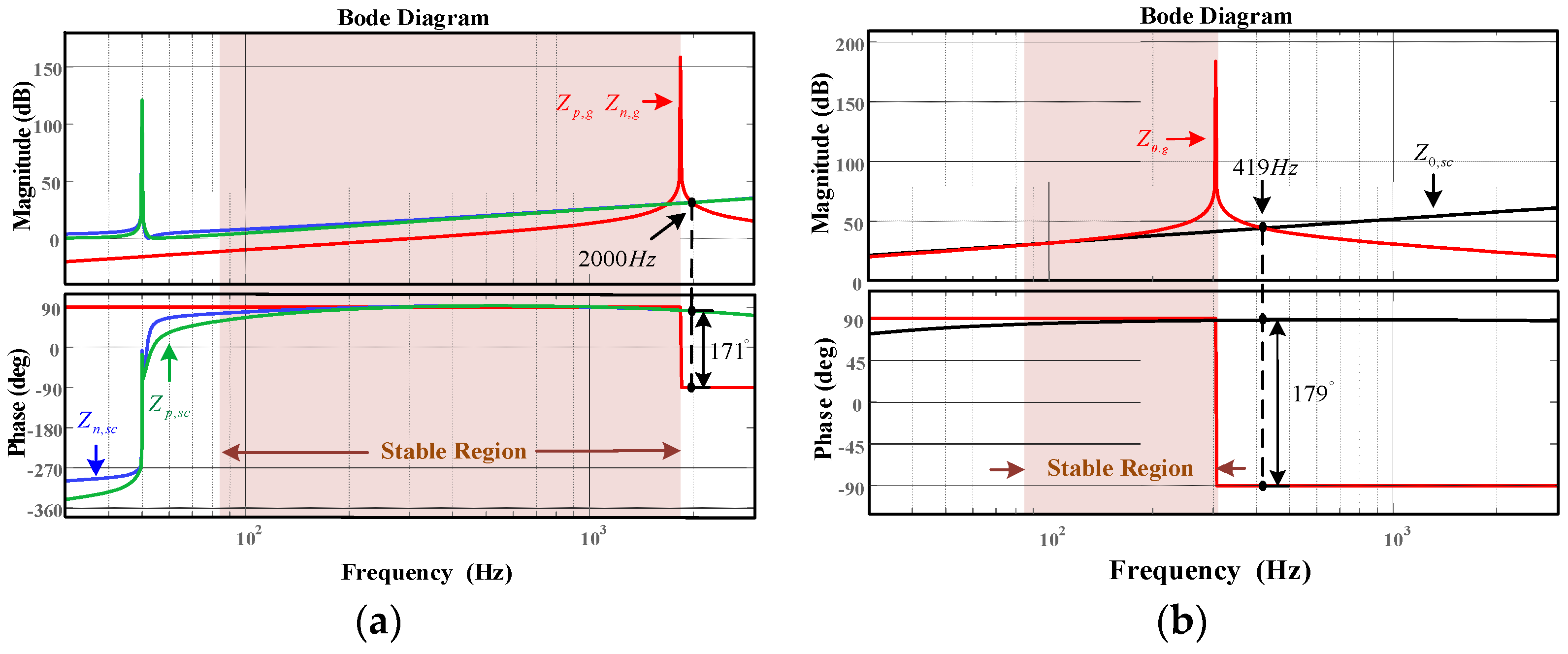
3. Stability Analysis of LCL-TFSCI

In order to analyze the stability of LCL-TFSCI when it is connected to the grid with parallel compensation capacitors, it is necessary to first analyze the mathematical model of the grid with parallel compensation capacitors. Figure 5 shows the circuit model of LCL-TFSCI connected to the grid with parallel compensation capacitors, where Cg denotes for the grid-side parallel compensation capacitor.
According to the circuit theory, the positive-sequence, negative-sequence, and zero-sequence equivalent impedance of the grid with parallel compensation capacitors can be expressed as:
Z p , g = Z n , g = s 2 C g L g + s L g s 2 C g L g + s C g + 1
Z 0 , g = s ( 1 + s C g ) ( L g + 3 L g n ) s 2 C g ( L g + 3 L g n ) + 1 + s C g
In order to analyze the stability of the LCL-TFSCI in a weak grid when it is connected to the grid with parallel compensation capacitors, according to Equations (21)–(23) and Equations (24) and (25), the Bode diagram of impedance of LCL-TFSCI and the power grid can be obtained as shown in Figure 6.
In the weak grid, a certain phase margin is required at the frequency of the intersection of the amplitude-frequency characteristic curve between Zpn0,sc and Zpn0,g according to the impedance stability theory [32]. It is assumed that the intersection frequency of the inverter and grid impedance is fc; the system phase margin PM can then be expressed as:
P M = 180 + Z p n 0 , s c ( j 2 π f c ) Z p n 0 , g ( j 2 π f c )
The frequency of the intersection of the amplitude-frequency characteristic curve between the positive sequence, negative sequence, and zero-sequence impedance of the inverter and the grid impedance are 2000 Hz, 2000 Hz, and 419 Hz, respectively. According to Equation (26), the positive-sequence, negative-sequence, and zero-sequence PM of the inverter is low at this time, which shows that the positive and negative sequence systems have an instability risk mainly in the high-frequency band, while the zero-sequence system is mainly in the mid-frequency band. In summary, the LCL-TFSCI is put at the risk of oscillation instability when it is connected to the grid with parallel compensation capacitors.

4. Research on an Oscillation-Suppression Method for LCL-TFSCI

4.1. Research on an Impedance-Reshaping Method for Inverters

The main reason for the oscillation instability of LCL-TFSCI can be found based on the relevant analysis in Section 3. Due to the limited output impedance amplitude of the inverter system, the impedance of the inverter and the grid with parallel compensation capacitors intersects at two points located at the left and right of the grid impedance amplitude jump point. Since the amplitude jump occurs at the same time as the phase jump of the grid impedance, the phase difference between the inverter impedance and the grid impedance becomes larger at the right intersection point. At this time, the stability margin of the inverter system is reduced, which exposes the system to a greater risk of oscillation instability.
In order to reduce the risk of oscillation instability for LCL-TFSCI, it is necessary to improve the system phase margin by increasing the amplitude of the impedance of the inverter system or reducing its phase to reduce the risk of system instability. Figure 7 shows the analysis diagram of the impedance vector condition of the ideal reshaping process of the inverter with short circuit ratio (SCR) changing. Considering the variation range of SCR is 3–18, at this time the frequency variation range of the intersection between the inverter positive-sequence, negative-sequence impedance and grid equivalent impedance is 1354 Hz–2105 Hz according to the relevant parameters of the inverter. Similarly, the frequency variation range of zero-sequence system is 405 Hz–422 Hz.
In Figure 7a, Zpn,sc represents the inverter output impedance before reshaping. In order to improve the phase margin of inverter, it is necessary to obtain the reshaped inverter impedance Zpn,re by introducing the reshaping vector Zv. When the input frequency increases, the inverter output impedance becomes Zpn,sc. In order to satisfy the stability criterion, the reshaping vector should be changed to Zv to obtain the reshaped inverter impedance Zpn,re in this case. As revealed by the above analysis, the ideal reshaping process for positive-sequence and negative-sequence systems is equivalent to connecting a variable impedance in series with the original inverter output impedance that increases in amplitude and decreases in phase with frequency increasing in the high-frequency band, which increases the amplitude and decreases the phase of the reshaped inverter impedance. Similarly, it can be seen from Figure 7b that for the zero-order system, the output characteristic of the reshaping vector in the mid-frequency band remains the same as that of the high-frequency band mentioned above.
Therefore, an oscillation-suppression method based complex filter and combined differential elements for LCL-TFSCI is proposed in this paper. It relies on the phase attenuation characteristic of the complex filter in middle and high frequency band to adjust the inverter output phase. In addition, negative differential elements are used to increase the order of the inverter system, thus raising the amplitude-frequency characteristic curve in its middle and high frequency band.
The block diagram of the complex filter structure is shown in Figure 8, from which the transfer function of the complex filter can be expressed as:
G F = U 2 U 1 = ω c ( s + j ω ^ ) ( s 2 + 2 ω c s + ω ^ 2 )
where ω ^ represents the fundamental frequency angular frequency of the power grid and ω c represents the cutoff frequency of the filter.
At the same time, the order of the negative differential elements in the reshaping method can be designed flexibly. The higher the order, the better the separation effect of the fundamental frequency control from high-frequency damping control of the system. However, an overly high order will increase the difficulty of system control. Therefore, the negative second-order combined differential element is adopted in this paper as a way of compromise. The proposed oscillation damping controller Qv is added to the current controller of the inverter and it can be expressed as:
Q v = G F G v = ω c ( s + j ω ^ ) / ( s 2 + 2 ω c s + ω ^ 2 ) ( k s 2 + s )
where Gv denotes the selected combined differential elements and k represents the controller gain.
Figure 9 shows Bode diagram of Qv. It can be observed that the amplitude of Qv increases linearly and the phase decreases progressively towards −90° with frequency increasing in the middle and high frequency band, which shows that the designed oscillation damping controller Qv has the same output characteristic as the ideal reshaping impedance Zv described in Figure 7. Therefore, Qv satisfies the vector condition of the reshaping process.
Figure 10 shows small-signal control block diagram of LCL-TFSCI after impedance reshaping. The proposed method is equivalent to introducing the additional impedance Qv into the inverter output impedance model. Figure 11 shows equivalent model of interactive system between LCL-TFSCI and grid after impedance reshaping.
At this time, the impedance matrix of LCL-TFSCI in the d-q-0 frame can be derived as:
Z d q 0 , r e = I [ ( H u i H u c 1 ) H c i + H d e c + Q v ] H d c H d e l H i d { H d e l H i d [ H P L L i ( H d e c + Q v H c i ) H d c H P L L d ] + ( Z o u t 1 + Z o u t 1 H i c 1 H i c 1 ) }
According to Equations (23) and (29), Bode diagram for the reshaped impedance of LCL-TFSCI and the grid with parallel compensation capacitors can be obtained as shown in Figure 12. It can be observed that the frequency of the intersection of the amplitude-frequency characteristic curve between the positive-sequence, negative-sequence and zero-sequence impedance of the reshaped inverter and the grid impedance are 1850 Hz, 1850 Hz and 313 Hz, respectively. According to the impedance stability theory, the positive-sequence, negative-sequence and zero-sequence system for LCL-TFSCI can maintain stable at this time. As revealed by the above analysis, the amplitude of the reshaped inverter impedance increases but the phase decreases. There is a significant increase in the stability margin of the reshaped inverter, which evidences the effectiveness of the proposed method of oscillation suppression for LCL-TFSCI. In addition, comparing Figure 6 with Figure 12, it can be observed that the stability region becomes larger for the positive-sequence, negative-sequence, and zero-sequence system of LCL-TFSCI after reshaping. Therefore, the proposed method can also achieve oscillation suppression within the wide frequency range.

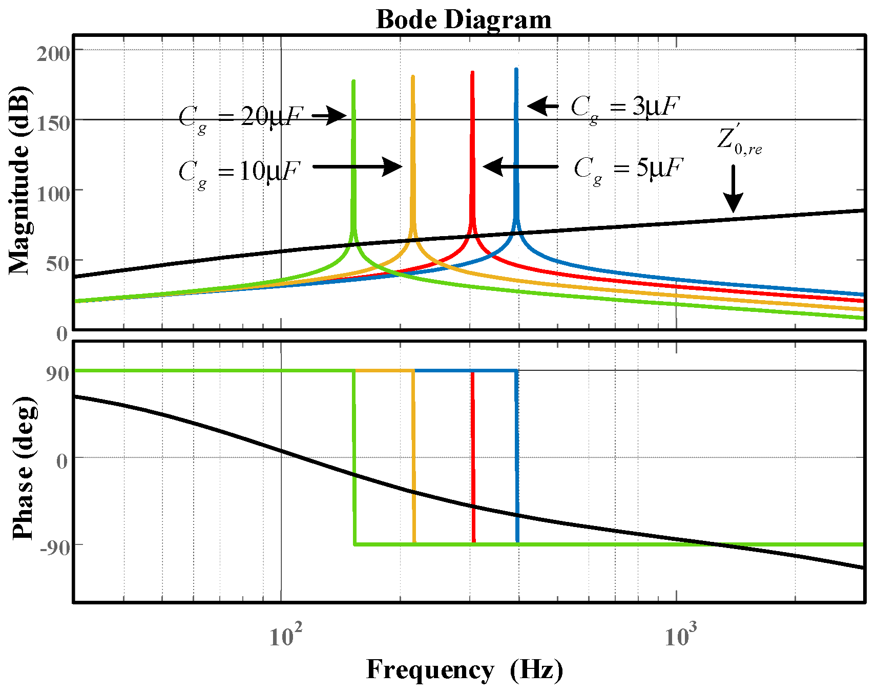
4.2. Parameter Analysis

In order to determine the range of parameters for the proposed oscillation damping controller and verify its adaptability to the changes of grid parameters, the effect of impedance reshaping will be discussed in this section when different damping controller gain k and the parallel compensation capacitors Cg are applied by taking the inverter zero-sequence system as an example.
Figure 13 shows Bode diagram for the zero-sequence impedance of LCL-TFSCI and grid impedance when different k is applied. It can be found that the output impedance amplitude of the inverter increases with k increasing when the proposed oscillation damping controller Qv is used, but its phase remains almost unchanged. There is a large stability margin for the inverter. In this paper, the damping controller gain k = 5 is adopted as a way of compromise to ensure the fundamental frequency control performance of the inverter and sufficient phase margin. The same method is used to obtain the controller gain of positive-sequence and negative-sequence system, which is also taken as 5.
Figure 14 shows Bode diagram for the zero-sequence impedance of LCL-TFSCI and grid impedance when different Cg is applied. The analysis reveals that the proposed oscillation-suppression method remains capable to ensure the large stability margin of LCL-TFSCI when the parallel compensation capacitors Cg vary. The risk of system oscillation instability is significantly reduced, thus demonstrating that the proposed method is still highly adaptable with Cg changing.
Summarizing the above analysis, the design flow chart of the proposed oscillation-suppression method can be obtained as shown in Figure 15.

5. Simulation and Experimental Verification

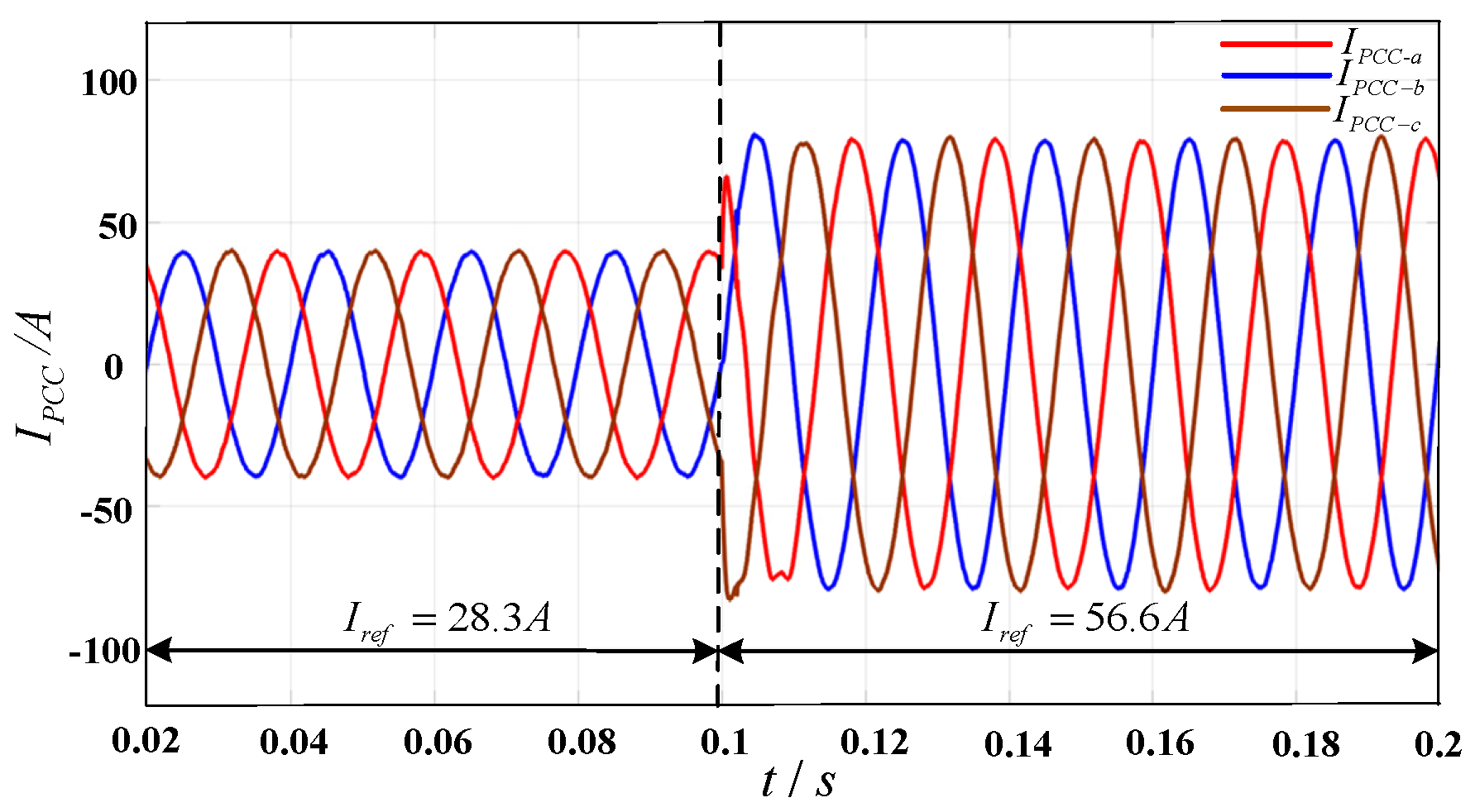
5.1. Simulation Verification

To verify the effectiveness of oscillation-suppression method proposed in this paper, the simulation model of LCL-TFSCI is established with MATLAB/SIMULINK. The relevant parameters of the inverter are shown in Table 2.
Figure 16a shows the simulation result of current waveform at PCC in the weak grid without parallel compensation capacitors. It can be observed that the current waveform is relatively smooth and the inverter can operate stably. Figure 16b shows simulation result of current waveform at PCC with parallel compensation capacitors. At this time, the inverter system is destabilized, which verifies that the addition of parallel compensation capacitors in the weak grid will cause oscillation instability for LCL-TFSCI.
Figure 17 shows simulation result of current waveform at PCC when different Cg is applied, in which the parallel compensation capacitors is 3 μF before 0.08 s. At this time, the system cannot run stably. The oscillation damping controller Qv is enabled at 0.08 s. It can be observed that the oscillation phenomenon is suppressed within 0.005 s and the system can resume stable operation rapidly. At the same time, THD of IPCC drops from 16.89% to 1.7%. To further verify the adaptability of the proposed control method when the parallel capacitors Cg are varied, Cg is increased to 5 μF at 0.14 s in the simulation. At this time, the inverter system can still maintain stable operation, thus verifying that the proposed control strategy has strong adaptability for changing of compensation degree.
To verify the dynamic characteristic of the proposed oscillation-suppression method when the main parameters of the system are changed, Figure 18 shows a simulation result of the current waveform at PCC after reshaping when the reference current of TFSCI is changed. It can be observed that when the reference current of LCL-TFSCI changes to twice the original value at 0.1 s, the inverter has the superb transient dynamic response performance and can quickly enter a new stable state within 0.004 s.
In order to verify the adaptability of the proposed control method to the grid-side equivalent inductances Lg, Figure 19 shows simulation result of current waveform at PCC after reshaping when the grid-side equivalent inductances change, in which the inductances Lg change from 5 mH to 10 mH. It can be observed that when the inductances Lg change, the inverter can resume stable operation within 0.005 s, and the output grid current of LCL-TFSCI has the high power quality, which verifies the proposed control method has strong adaptability for changing the grid-side equivalent inductances in the weak grid.
In addition, since the stability of the inverter-grid interaction system in the weak grid is much more sensitive to the proportional coefficient kpp of PLL than its integral coefficient kip, in order to verify the adaptability of the proposed control method to the parameter changes of the PI controller in PLL, Figure 20 shows simulation result of the current waveform at PCC after reshaping when the proportional coefficient of PLL changes, in which kpp changes from 0.16 to 0.5. It can be observed that the dynamic response speed of the inverter is faster and it can enter the new stable state within 0.003 s, thus verifying that the proposed control method is also highly adaptable to the parameter of the PI controller in PLL.
Figure 21 shows the simulation result of the current waveform at PCC after injecting the fifth and seventh harmonic voltage, in which the harmonic content of both is 0.1 pu. When the oscillation damping controller Qv is enabled after 0.1 s, oscillation instability can be quickly suppressed and the system can run stably. Figure 22 shows FFT analysis of the inverter output current before and after reshaping. When the damping controller Qv is added to LCL-TFSCI, the THD of IPCC is significantly reduced from 17.63% to 2.52%, which indicates that the proposed control method can suppress harmonic voltage and ensure the stable operation of LCL-TFSCI.
Finally, to verify the oscillation-suppression effect of the proposed control method on the zero-sequence system, Figure 23 shows simulation waveform of the current in the midline before and after reshaping. When the oscillation damping controller Qv is enabled after 0.1 s, the zero-sequence current converges to 0 rapidly and the system has a good performance in the transient process, which verifies that the proposed control method is effective in suppressing zero-sequence oscillation for LCL-TFSCI.

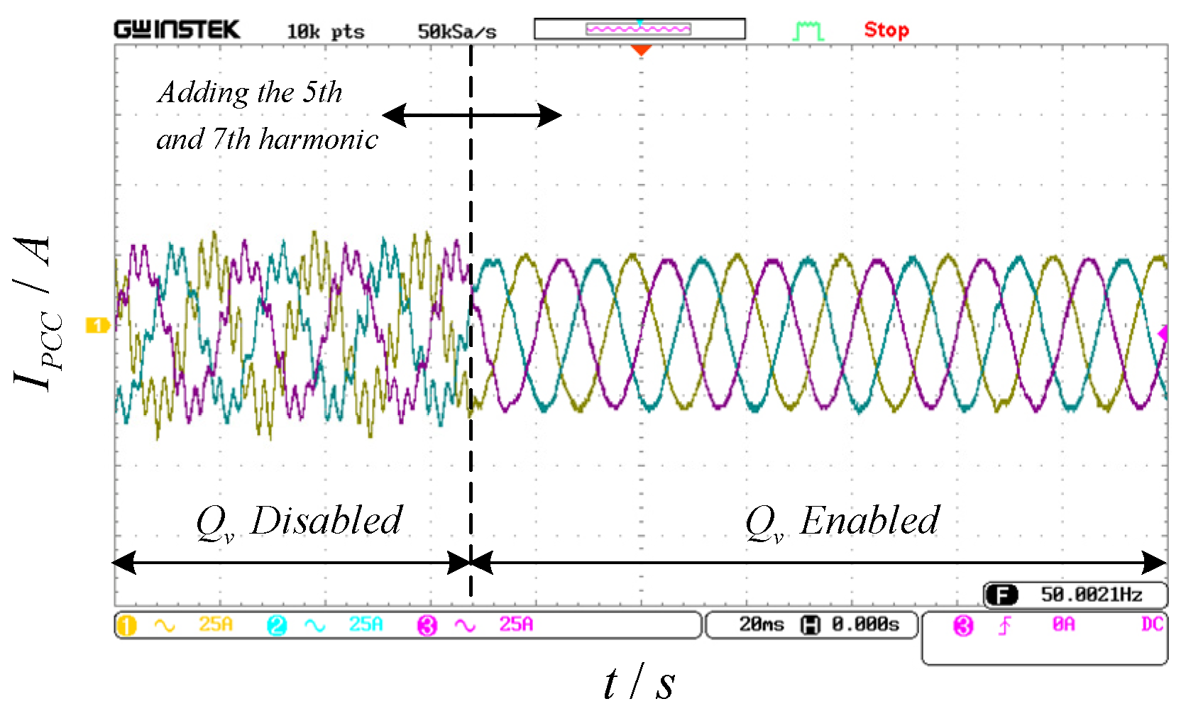
5.2. Experimental Verification

In order to further verify the correctness and effectiveness of the oscillation-suppression method proposed in this paper, the experimental platform of LCL-TFSCI is built based on RTDS as shown in Figure 24. The control link of the inverter is implemented on the TMS320F28335/Spartan6XC6SLX16 DSP+FPGA.
First of all, to verify the impact of grid-side parallel compensation capacitors on system stability, Figure 25a shows the experimental result of the current waveform at PCC, in which Lg is 1mH and there is no parallel compensation capacitor. It can be observed that the inverter can operate stably at this time and the power quality of Ipcc is better. Figure 25b shows the experimental result of the current waveform at PCC when the grid-side parallel compensation capacitors are 5 μF, which indicates the addition of parallel compensation capacitors significantly reduces the stability margin of the inverter. From the above analysis, it can be observed that the addition of parallel compensation capacitors increasingly destabilizes the LCL-TFSCI.
Subsequently, to verify the effectiveness of the oscillation-suppression method proposed in this paper, Figure 26 shows the experimental result of the current waveform at PCC before and after reshaping. It can be observed that the system can resume stable operation within 0.005 s after adding an oscillation-damping controller Qv. At this time, the current waveform at PCC is relatively smooth and the THD of IPCC drops from 17.19% to 2.04%, thus verifying that the proposed method can effectively suppress oscillation instability for LCL-TFSCI when there are parallel compensation capacitors in the grid. To further verify adaptability to the changes in parallel compensation capacitors for the proposed method, the parallel capacitor is switched from 5 μF to 12 μF. It can be observed that the inverter continues to operate stably and maintains a fast rate of dynamic response when the different parallel compensation capacitors are applied, which verifies the proposed method has the adaptability for changing the parallel compensation capacitors.
To verify the dynamic characteristics of the proposed oscillation-suppression method, Figure 27 shows the experimental result of the current waveform at PCC after reshaping when the reference current of TFSCI is changed. When the reference current of LCL-TFSCI changes from 19.4 A to 38.8 A, the inverter can quickly resume the stable state within 0.005 s.
Meanwhile, since the grid-side equivalent inductances can change with time in the weak grid, in order to verify the adaptability of the proposed control method to the grid-side equivalent inductances Lg, Figure 28 shows the experimental result of the current waveform at PCC after reshaping when the grid-side equivalent inductances change, in which the inductances Lg change from 4 mH to 10 mH. It can be observed that the inverter operates stably before and after the change in inductance Lg, and the current at PCC has high power quality, which verifies the proposed control method has strong adaptability for the grid-side equivalent inductance in the weak grid.
In addition, Figure 29 shows the experimental result of the current waveform at PCC after reshaping when the proportional coefficient of PLL changes, in which kpp changes from 0.16 to 0.48. It can be observed that the dynamic response time of the inverter is short and it can enter a new stable state within 0.004 s, which verifies the proposed control method has strong adaptability for the proportional coefficient kpp of PLL.
Finally, to verify the harmonic suppression capability of the proposed control method, Figure 30 shows the experimental result of the current waveform at PCC after injecting harmonic voltage, in which the fifth and seventh harmonic contents of both are 0.15 pu. When the grid is connected to the parallel compensation capacitors and the traditional control method is used, the THD of IPCC is 17.82%. At this time, the LCL-TFSCI cannot operate stably. When the damping controller Qv is added to the inverter, the THD of IPCC drops to 2.7%. The experimental result indicates the inverter can operate stably after impedance reshaping even when the harmonic content of the grid is high, which suggests that the proposed control method is also effective in suppressing oscillation instability for LCL-TFSCI in the harmonic grid.

6. Conclusions

In this paper, an impedance model of LCL-TFSCI considering the dynamic characteristic of the PI controller in PLL and the zero-sequence loop under multiple small-signal perturbations is established, which solves the modelling challenge caused by the asymmetry of the d-q frame in a small-signal perturbation state. Besides this, an oscillation-suppression method is proposed and verified by simulation and experimentation, which can improve the stability of the grid-connected system without adding excessive control complexity. The contributions of this paper can be established as follows.
(1) An impedance model of LCL-TFSCI considering the zero-sequence loop and the interaction effect of the dual d-q-0 frame is established, which makes the matrix dimension of the impedance model increase from 2D to 3D. The constructed 3D impedance model can be used for the stability analysis of LCL-TFSCI, which contributes to revealing the instability risk of inverters in the weak grid.
(2) The instability risk of positive-sequence, negative-sequence, and zero-sequence systems is revealed when the LCL-TFSCI is connected to the grid with parallel compensation capacitors. The analysis shows that the LCL-TFSCI is at high oscillation instability risk in the grid with parallel compensation capacitors.
(3) An impedance-reshaping method based on the complex filter and combined differential elements is proposed, which can simultaneously reshape the positive-sequence, negative-sequence, and zero-sequence impedance of LCL-TFSCI within the wide frequency range, thus achieving oscillation suppression and expanding the region of stable operation for the inverter.
It Is worth illustrating that how to quantitatively design the main control parameters with the objective of maximizing the stability domain of LCL-TFSCI will be the further work to be explored.

Author Contributions

Conceptualization, L.Y. and T.C.; methodology, Z.C.; software, Z.C. and X.X.; validation, L.Y., S.Z. and C.J.; formal analysis, X.D. and T.C.; resources, C.J.; writing—original draft preparation, T.C. and X.X.; writing—review and editing, S.Z.; funding acquisition, C.J. and L.Y. All authors have read and agreed to the published version of the manuscript.

Funding

This research was funded in part by the National Key Research and Development Program of China under Grant 2021YFC3100304, the Qing Lan Project for the University Key Teacher from Jiangsu Education Department (2020), and in part by the Key Research and Development Program of the XuZhou Municipal under Grant KC19224.

Institutional Review Board Statement

Not applicable.

Informed Consent Statement

Not applicable.

Data Availability Statement

Not applicable.

Conflicts of Interest

The authors declare no conflict of interest.

Abbreviations

LCL-TFSCILCL-type three-phase four-wire split capacitor inverter
TFSCIThree-phase four-wire split capacitor inverter
SRF-PLLSynchronous reference frame phase-locked loop
PLLPhase-locked loop
PMPhase margin
PCCPoint of common coupling
THDTotal harmonic distortion
SCRShort-circuit ratio
RTDSReal time digital simulation system
FFTFast Fourier transform

References

  1. Zhang, Z.; Ding, W. Improved active disturbance rejection control strategy for LCL-Type grid-connected inverters based on the backstepping method. Electronics 2022, 11, 2237. [Google Scholar] [CrossRef]
  2. Lin, Z.; Ruan, X.; Jia, L.; Zhao, W.; Liu, H.; Rao, P. Optimized design of the neutral inductor and filter inductors in three-phase four-wire inverter with split DC-link capacitors. IEEE Trans. Power Electron. 2019, 34, 247–262. [Google Scholar] [CrossRef]
  3. Mandrioli, R.; Hammami, M.; Viatkin, A.; Barbone, R.; Pontara, D.; Ricco, M. Phase and neutral current ripple analysis in three-phase four-wire split-capacitor grid converter for EV chargers. Electronics 2021, 10, 1016. [Google Scholar] [CrossRef]
  4. Zhou, X.; Tang, F.; Loh, P.C.; Jin, X.; Cao, W. Four-leg converters with improved common current sharing and selective voltage-quality enhancement for islanded microgrids. IEEE Trans. Power Deliv. 2016, 31, 522–531. [Google Scholar] [CrossRef] [Green Version]
  5. Hirve, S.; Chatterjee, K.; Fernandes, B.G.; Imayavaramban, M.; Dwari, S. PLL-less active power filter based on one-cycle control for compensating unbalanced loads in three-phase four-wire system. IEEE Trans. Power Deliv. 2007, 22, 2457–2465. [Google Scholar] [CrossRef]
  6. De Morais, A.S.; Lessa Tofoli, F.; Barbi, I. Modeling, digital control, and implementation of a three-phase four-wire power converter used as a power redistribution device. IEEE Trans. Ind. Inf. 2016, 12, 1035–1042. [Google Scholar] [CrossRef]
  7. Kerekes, T.; Teodorescu, R.; Liserre, M.; Klumpner, C.; Sumner, M. Evaluation of three-phase transformerless photovoltaic inverter topologies. IEEE Trans. Power Electron. 2009, 24, 2202–2211. [Google Scholar] [CrossRef]
  8. Pichan, M.; Rastegar, H. Sliding-mode control of four-leg inverter with fixed switching frequency for uninterruptible power supply applications. IEEE Trans. Ind. Electron. 2017, 64, 6805–6814. [Google Scholar] [CrossRef]
  9. Carlos, G.A.d.A.; Jacobina, C.B.; Dos Santos, E.C. Investigation on dynamic voltage restorers with two DC links and series converters for three-phase four-wire systems. IEEE Trans. Ind. Appl. 2016, 52, 1608–1620. [Google Scholar] [CrossRef]
  10. Hadavi, S.; Mansour, M.Z.; Bahrani, B. Optimal allocation and sizing of synchronous condensers in weak grids with increased penetration of wind and solar farms. IEEE J. Emerg. Sel. Top. Power Electron. 2021, 11, 199–209. [Google Scholar] [CrossRef]
  11. Xu, H.; Yu, C.; Mao, F.; Hu, T.; Wu, Z.; Wang, Q. Research on direct power control strategy based on voltage controlled virtual synchronous generator. Electronics 2021, 10, 2415. [Google Scholar] [CrossRef]
  12. Elkholy, A.M.; Taha, I.B.M.; Kamel, S.; El-Nemr, M.K. Grid synchronization enhancement of distributed generators using an adaptive phase-locked loop tuning system. Electronics 2022, 11, 702. [Google Scholar] [CrossRef]
  13. Song, Y.; Blaabjerg, F.; Wang, X. Analysis and active damping of multiple high frequency resonances in DFIG System. IEEE Trans. Energy Convers. 2017, 32, 369–381. [Google Scholar] [CrossRef] [Green Version]
  14. Pang, B.; Wu, C.; Nian, H.; Blaabjerg, F. Damping method of high-frequency resonance for stator current controlled DFIG system under parallel compensation grid. IEEE Trans. Power Electron. 2020, 35, 10260–10270. [Google Scholar] [CrossRef]
  15. Song, Y.; Blaabjerg, F. Overview of DFIG-based wind power system resonances under weak networks. IEEE Trans. Power Electron. 2017, 32, 4370–4394. [Google Scholar] [CrossRef] [Green Version]
  16. Sainz, L.; Cheah-Mane, M.; Monjo, L.; Liang, J.; Gomis-Bellmunt, O. Positive-net-damping stability criterion in grid-connected VSC systems. IEEE J. Emerg. Sel. Top. Power Electron. 2017, 5, 1499–1512. [Google Scholar] [CrossRef]
  17. Nian, H.; Pang, B. Stability and power quality enhancement strategy for DFIG system connected to harmonic grid with parallel compensation. IEEE Trans. Energy Convers. 2019, 34, 1010–1022. [Google Scholar] [CrossRef]
  18. Wang, X.; Blaabjerg, F.; Loh, P.C. Virtual RC damping of LCL-filtered voltage source converters with extended selective harmonic compensation. IEEE Trans. Power Electron. 2015, 30, 4726–4737. [Google Scholar] [CrossRef] [Green Version]
  19. Xu, J.; Xie, S.; Tang, T. Improved control strategy with grid-voltage feedforward for LCL-filter-based inverter connected to weak grid. IET Power Electron. 2014, 7, 2660–2671. [Google Scholar] [CrossRef]
  20. Cespedes, M.; Sun, J. Adaptive control of grid-connected inverters based on online grid impedance measurements. IEEE Trans. Sustain Energy. 2014, 5, 516–523. [Google Scholar] [CrossRef]
  21. Chen, X.; Zhang, Y.; Wang, S.; Chen, J.; Gong, C. Impedance-phased dynamic control method for grid-connected inverters in a weak Grid. IEEE Trans. Power Electron. 2017, 32, 274–283. [Google Scholar] [CrossRef]
  22. Huang, L.; Wu, C.; Zhou, D.; Blaabjerg, F. A double-PLLs-based impedance reshaping method for extending stability range of grid-following inverter under weak grid. IEEE Trans. Power Electron. 2022, 37, 4091–4104. [Google Scholar] [CrossRef]
  23. Wang, K.; Yuan, X.; Wang, H.; Li, S.; Wu, X. Mitigation of subsynchronous resonance for grid-connected inverters in series-compensated weak power grids through observed q-axis grid voltage feedback. IEEE Trans. Ind. Electron. 2022, 69, 10236–10248. [Google Scholar] [CrossRef]
  24. Rygg, A.; Molinas, M.; Zhang, C.; Cai, X. A modified sequence-domain impedance definition and its equivalence to the dq-domain impedance definition for the stability analysis of AC power electronic systems. IEEE J. Emerg. Sel. Top. Power Electron. 2016, 4, 1383–1396. [Google Scholar] [CrossRef] [Green Version]
  25. Bakhshizadeh, M.K.; Wang, X.; Blaabjerg, F.; Hjerrild, J.; Kocewiak, Ł.; Bak, C.L.; Hesselbæk, B. Couplings in phase domain impedance modeling of grid-connected converters. IEEE Trans. Power Electron. 2016, 31, 6792–6796. [Google Scholar]
  26. Shah, S.; Parsa, L. Impedance modeling of three-phase voltage source converters in dq, sequence, and phasor domains. IEEE Trans. Energy Convers. 2017, 32, 1139–1150. [Google Scholar] [CrossRef]
  27. Wang, X.; Li, Y.W.; Blaabjerg, F.; Loh, P.C. Virtual-impedance-based control for voltage-source and current-source converters. IEEE Trans. Power Electron. 2015, 30, 7019–7037. [Google Scholar] [CrossRef]
  28. Fang, J.; Li, X.; Li, H.; Tang, Y. Stability improvement for three-phase grid-connected converters through impedance reshaping in quadrature-axis. IEEE Trans. Power Electron. 2018, 33, 8365–8375. [Google Scholar] [CrossRef]
  29. Wang, Y.; Chen, X.; Zhang, Y.; Chen, J.; Gong, C. Impedance modeling of three-phase grid-connected inverters and analysis of interaction stability in grid-connected system. In Proceedings of the 2016 IEEE 8th International Power Electronics and Motion Control Conference (IPEMC-ECCE Asia), Hefei, China, 22–26 May 2016; pp. 3606–3612. [Google Scholar] [CrossRef]
  30. Nian, H.; Liao, Y.; Li, M.; Sun, D.; Xu, Y.; Hu, B. Impedance modeling and stability analysis of three-phase four-leg grid-connected inverter considering zero-sequence. IEEE Access 2021, 9, 83676–83687. [Google Scholar] [CrossRef]
  31. Cespedes, M.; Sun, J. Impedance modeling and analysis of grid-connected voltage-source converters. IEEE Trans. Power Electron. 2014, 29, 1254–1261. [Google Scholar] [CrossRef]
  32. Wang, X.; Harnefors, L.; Blaabjerg, F. Unified impedance model of grid-connected voltage-source converters. IEEE Trans. Power Electron. 2018, 33, 1775–1787. [Google Scholar] [CrossRef]
Figure 1. Equivalent control diagram of LCL-TFSCI connected to the grid.
Electronics 11 03286 g001
Figure 2. Control diagram of SRF-PLL.
Electronics 11 03286 g002
Figure 3. Relationship between the control d-q-0 frame and the system d-q-0 frame.
Electronics 11 03286 g003
Figure 4. Small-signal control diagram of LCL-TFSCI.
Electronics 11 03286 g004
Figure 5. Circuit model of LCL-TFSCI connected to the grid with parallel compensation capacitors.
Electronics 11 03286 g005
Figure 6. Bode diagram of impedance of LCL-TFSCI and the power grid. (a) Positive-sequence and negative-sequence; (b) Zero-sequence.
Electronics 11 03286 g006
Figure 7. Analysis diagram of the impedance vector condition of the ideal reshaping process of LCL-TFSCI with SCR changing. (a) Ideal reshaping process for positive and negative sequence system; (b) Ideal reshaping process for zero-sequence system.
Electronics 11 03286 g007
Figure 8. Block diagram of complex filter structure.
Electronics 11 03286 g008
Figure 9. Bode diagram of Qv.
Electronics 11 03286 g009
Figure 10. Small-signal control block diagram of LCL-TFSCI after impedance reshaping.
Electronics 11 03286 g010
Figure 11. Equivalent model of interactive system between LCL-TFSCI and grid after impedance reshaping.
Electronics 11 03286 g011
Figure 12. Bode diagram for the reshaped impedance of LCL-TFSCI and the grid with parallel compensation capacitors. (a) Positive-sequence and negative-sequence; (b) Zero-sequence.
Electronics 11 03286 g012
Figure 13. Bode diagram for the zero-sequence impedance of LCL-TFSCI and grid impedance when different k is applied.
Electronics 11 03286 g013
Figure 14. Bode diagram for the zero-sequence impedance of LCL-TFSCI and grid impedance when different Cg is applied.
Electronics 11 03286 g014
Figure 15. Design flow chart of the proposed oscillation-suppression method.
Electronics 11 03286 g015
Figure 16. Simulation result of current waveform at PCC with and without parallel compensation capacitors. (a) Without parallel compensation capacitors; (b) With parallel compensation capacitors.
Electronics 11 03286 g016
Figure 17. Simulation result of current waveform at PCC when different Cg is applied.
Electronics 11 03286 g017
Figure 18. Simulation result of current waveform at PCC after reshaping when the reference current of TFSCI changes.
Electronics 11 03286 g018
Figure 19. Simulation result of current waveform at PCC after reshaping when the grid-side equivalent inductances change.
Electronics 11 03286 g019
Figure 20. Simulation result of current waveform at PCC after reshaping when the proportional coefficient of PLL changes.
Electronics 11 03286 g020
Figure 21. Simulation result of current waveform at PCC after injecting 5th and 7th harmonic voltage.
Electronics 11 03286 g021
Figure 22. FFT analysis of the inverter output current before and after reshaping. (a) Qv disabled; (b) Qv enabled.
Electronics 11 03286 g022
Figure 23. Simulation waveform of the current in the midline before and after reshaping.
Electronics 11 03286 g023
Figure 24. Experimental platform of LCL-TFSCI.
Electronics 11 03286 g024
Figure 25. Experimental result of current waveform at PCC with and without parallel compensation capacitors: (a) Without parallel compensation capacitors, (b) With parallel compensation capacitors.
Electronics 11 03286 g025aElectronics 11 03286 g025b
Figure 26. Experimental result of current waveform at PCC before and after reshaping.
Electronics 11 03286 g026
Figure 27. Experimental result of current waveform at PCC after reshaping when the reference current of TFSCI changes.
Electronics 11 03286 g027
Figure 28. Experimental result of current waveform at PCC after reshaping when the grid-side equivalent inductances change.
Electronics 11 03286 g028
Figure 29. Experimental result of current waveform at PCC after reshaping when the proportional coefficient of PLL changes.
Electronics 11 03286 g029
Figure 30. Experimental result of current waveform at PCC after injecting harmonic voltage.
Electronics 11 03286 g030
Table 1. Overview of the current research on inverter stability improvement methods.
ClassificationApplication MethodShortcoming
stability improvement methods without considering PLLrobust active damping and current control methodpoor availability in weak grid
grid-voltage feed-forward control methodintroduction of negative phase shift
adaptive method based on impedance measurementdependent on impedance detection accuracy
stability improvement methods considering PLLimpedance-reshaping method based on virtual controller and impedance controllerincreased control complexity and inability to reshape within wide frequency range
adaptive feed-forward control method without analyzing zero-sequence loop
Table 2. Relevant parameters of LCL-TFSCI.
SymbolParameterValue
UdcDC-side voltage700 V
Porated power40 kW
f1fundamental frequency50 Hz
Cfilter capacitors15 μF
kppproportion coefficient of PLL0.16
kipintegral coefficient of PLL0.25
Uggrid voltage220 V
fsswitching frequency10 kHz
L1inverter-side inductance700 μH
L2grid-side inductance110 μH
Publisher’s Note: MDPI stays neutral with regard to jurisdictional claims in published maps and institutional affiliations.

