Abstract
“Tatami” is the most commonly used needle type in computer embroidery. Its uniform yarn, contact point and gap arrangement can greatly reduce the resistance of fabric electrodes (0.65 MΩ–4.9 MΩ) and the impedance between electrodes and human skin (2.455 MΩ), which can meet the requirements of intelligent wearable devices for long-time electrocardiogram monitoring. In this work, properties of a fabric electrode were tested. Its air permeability and wear resistance are good, although human sweat will lead to different degrees of resistance of stainless steel embroidery electrode. It will not change its performance too much. Generally speaking, the wearing performance and ECG (electrocardiogram) monitoring performance of the stainless steel embroidery electrode are stable.
1. Introduction
ECG monitoring clothing is a convenient and effective device that can capture and collect human ECG signals in real time to generate an electrocardiogram (ECG) and achieve cardiac monitoring and a nursing warning effect [1]. With its advantages of simple operation, low cost and non-invasive ECG detection, it is of great significance for the prevention, diagnosis and treatment of cardiovascular diseases. An electrocardiogram (ECG) is a regular and periodic bioelectrical signal generator which uses the electrical excitation of cardiac myocytes [2]. As one of the simplest and most accurate methods to detect cardiac-related diseases, ECG detection can make qualitative diagnoses of various types of diseases (such as Figure 1). However, heart-related diseases tend to be “transient”, which means they occur once in a short period of time, often with an obvious cause. In the process of ECG detection in the hospital, time is very limited. In this case, cardiovascular disease may not be found in time, and it is difficult to realize its prevention [3]. Statistics show that more than 17 million people worldwide die of cardiovascular diseases every year, accounting for 31% of the global death toll [4]. In China, cardiovascular disease, as the first chronic disease, has become the number one killer of people’s health. Although China’s medical resources for cardiovascular diseases may be close to those of developed countries, there is still a problem of unequal distribution. All in all, the treatment and control of cardiovascular diseases need to be improved, and there is a long way to go [5].
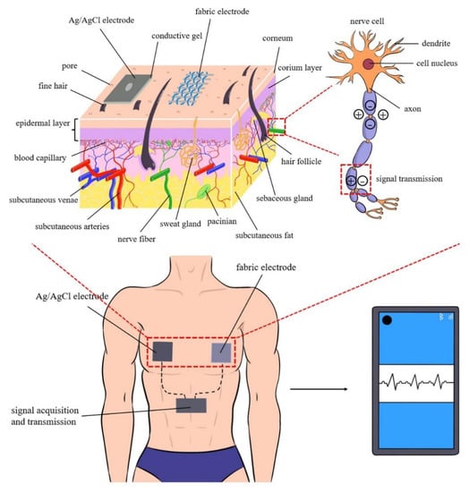
Figure 1.
The potential change generated when the heartbeats are transmitted to the skin surface through the nerve, and the electrode is attached to the skin surface to collect the potential change signal, which is transmitted to the electronic equipment through the signal transmission equipment (wire or Bluetooth, etc.).
As an important part of intelligent textiles, ECG monitoring clothing has been developing rapidly in recent years with the requirements of flexible, comfortable and reusable real-time monitoring [6]. Electrodes are the core component of ECG monitoring clothing [7]. The wet electrode (Ag/AgCl electrode) is the most commonly used in ECG monitoring and relies on conductive gel to fit on human skin [8,9]. It is necessary to clean the cuticle of the skin surface, which will cause slight damage to the epidermis. Sticking to the skin surface for a long time can affect the breathing of pores and the excretion of sweat from the body surface. Wet conductive gels tend to cause skin irritation, causing itching or redness [10]. As time goes on, the water in the conductive gel evaporates, and the signal collection of the electrode is biased. Therefore, the Ag/AgCl electrode is not the best candidate to be a wearable electrode used in ECG clothing. In addition, there are a variety of electrodes available for selection and use in wearable intelligent monitoring devices [11,12], such as a non-contact ECG electrode [13], fiber-based flexible electrode [14], paper-based flexible electrode [15,16], carbon-based flexible electrode [17,18], and fabric electrode. A textile electrode is a type of dry electrode, which is more skin-friendly and breathable, making it suitable for prolonged use. Therefore, a fabric electrode has high research value in material design and performance [19,20,21].
Textile electrodes usually adopt a special way to stick conductive material on the surface of fiber, yarn or fabric [22]. Conductive fiber, yarn or fabric after conductive treatment are commonly used materials. There are many kinds of fiber materials used for weaving textile electrodes, among which carbon fiber and graphene fiber are recognized as excellent materials. Among them, carbon fiber material has excellent physical properties, corrosion resistance, super high temperature resistance, good mechanical properties and point performance. There are many methods to prepare flexible electrode materials based on carbon fiber; each method has disadvantages and requires high processing technology. Therefore, mass production is harder to achieve [23]. Graphene is a kind of 1-dimentional nanomaterial, which has great potential in the research and application of electrode materials [24]. However, agglomeration and stacking occur easily in production [25]. This phenomenon will reduce the effective area and properties of graphene. At present, the preparation cost of graphene is still high with a complex process, and the performance of the actual material cannot reach the theoretical value. Compared with other metal fibers, stainless steel fibers with high temperature resistance, corrosion resistance, high strength and excellent electrical conductivity have advantages in spinnability, economy, production difficulty and practical use and play an important role in the design and manufacture of fabric dry electrodes to replace traditional electrodes [26].
Fabric electrodes can also be divided into five types: woven [27], knitted [28], nonwoven [29], printed and embroidered [30]. Among them, the embroidery electrode is flexible and convenient and can be designed freely, even with beautification and decoration effects, which is a potential candidate for ECG application. Yao Hu [31] prepared a new bioelectric dry electrode on the surface of a textile structure by embroidering silver-plated yarn. AgCl was plated on the surface of the electrode via electrochemical deposition, and the electrochemical performance of the embroidered electrode was evaluated. Silver-coated fibers are often used in embroidery electrodes, but they oxidize easily. Plating an AgCl protective layer on the surface using the electroplating method can slow down the oxidation of silver, however, the electroplating method brings more troubles in production preparation. Huijin Yuan [32] took silver-plated yarn as the basic material and prepared the embroidery flexible electrode fabric by means of chlorination modification, manual embroidery molding, circuit simulation, electroplating and textile technology. However, the electrocardiogram test with this electrode showed an obvious burr waveform and slight fluctuation of the baseline. Therefore, a new candidate should be discovered, and stainless steel blended yarn has been considered to be used to prepare embroidery fabric electrodes [33].
In this work, a new embroidery fabric electrode, a stainless steel yarn embroidery fabric electrode, was prepared using stainless steel blended yarn as the material and computer embroidery as the method. The durability of the electrode has been tested, and it can be used for ECG garments. According to the previous experimental results, the “Tatami” needle type and a stitch density of 0.2 mm and 0.3 mm were used to make a stainless steel embroidery fabric electrode. By testing the permeability, wear resistance and pilling performance of a stainless steel embroidery fabric electrode and the degree to which it is affected by human sweat, a stainless steel embroidery fabric electrode which can stably monitor a human ECG signal with good durability was prepared. The sample data obtained are shown in Table 1.

Table 1.
Preparation of electrode for embroidery fabric.
2. Materials and Methods
2.1. Stainless Steel Blended Yarn
Stainless steel fiber (Figure 2a) is a new kind of reinforcement material. It has high temperature resistance, corrosion resistance, spinnability, electrical conductivity and other excellent performance [34] and has been widely used in chemical, electronics, aerospace and other fields. Stainless steel yarns are fine and soft. Compared with other metal fibers, they have obvious advantages in spinnability, usability, economy and other aspects [35]. In recent years, they have also developed greatly in the special textile industry. Due to the poor binding force between stainless steel fibers, high stainless steel fiber content will reduce the tensile strength of yarn and affect the spinnability of yarn. Stainless steel yarns are often blended with stainless steel staple fiber and polyester fiber. The common blended ratio is polyester/steel (80/20) and polyester/steel (70/30). (Figure 2b is stainless steel yarn under a microscope.) Here, we use the latter as raw material to make fabric electrodes.

Figure 2.
(a) Stainless steel blended yarn, (b) structure diagram of stainless steel blended yarn computerized and (c) embroidery machine.
2.2. Preparation of Electrode for Embroidery Fabric
Computer embroidery technology (Figure 2c shows the computer embroidery machine) has become an important part of the garment fabric production field because of its simple process, easy operation, high efficiency and low cost [36]. Computer embroidery technology can accurately prepare the shape, size and position of the ECG electrode according to the file imported by computer software (such as Figure 3). Prior to this, we carried out related research on the influence of the embroidery process on the structure and performance of a stainless steel, blended yarn fabric electrode. It was found that different embroidery needle types (e.g., “Tatami” needle, “Sawtooth” needle, etc.) determined the internal yarn arrangement structure of the embroidery fabric electrode and stitch density determined the tightness of the yarn contact. Previous studies have shown that the performance of the stainless steel embroidery electrode with 0.2 mm needle spacing of “Tatami” is the best. However, in the preparation process of this kind of sample in the laboratory, the yarn and computer embroidery will produce larger friction, which needs a long time. Therefore, all experiments in this paper adopt “Tatami” needle spacing of 0.3 mm to test, and the gap between the two is not large.
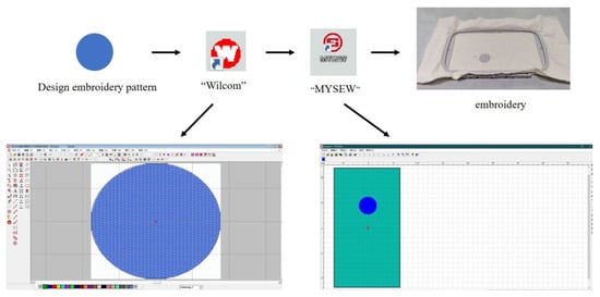
Figure 3.
The embroidery process. First, design the electrode pattern and size, and save as a picture. Import the “Wilcom” [37] software. After color analysis, pin design and pin filling settings, save as an “DST “file. Use “WYSEW” to import the document into the computer and set the position to begin embroidery.
A “Tatami” embroidery stitch (Figure 4) is a commonly used computerized embroidery stitch. The stitch arrangement is close and parallel, and the three-dimensional appearance is not strong. Commonly used at filling, it can embroider the graph of a large area or irregular graph. The finished product feels hard. The density of “Tatami” stitches refers to the distance between two adjacent stitches in the same direction. It is composed of the special arrangement of a single needle. These stitches span the entire figure in a direction that is perpendicular to the boundary of the figure to form a group of forward and return stitches. Each column of the stitch is arranged according to a certain offset value so as to an avoid obvious line on the surface of the embroidery fabric and affect the beauty of the embroidery.
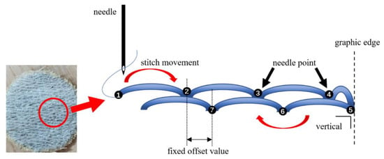
Figure 4.
“Tatami” stitch analysis (Dots 1–7 indicate the sequence of needle drop).
2.3. Fabric Electrode Performance Test
2.3.1. Air Permeability Test
In this experiment, a YG461E-III automatic air permeability gauge was used to measure the air permeability of the embroidery fabric electrode. Four stainless steel yarn embroidery electrodes with a diameter of 5.5 cm were prepared according to the hole size of the instrument itself (a circle with a diameter of about 5 cm) and two stitch densities of 0.2 mm and 0.3 mm, respectively. In the cutting process, grey cloth of some width should be reserved around the electrode of the embroidery fabric for sample holding and fixation in the process of the air permeability test. During sample placement, it should be ensured that the embroidery fabric electrode completely covers the air hole of the automatic air permeability measurement instrument to avoid inaccurate air permeability data due to uneven air flow. After the instrument is turned on, the test mode is set to automatic and the test can be started.
2.3.2. Fuzzing and Pilling Test
YG502N fabric pilling apparatus was used in this experiment. The surface of the fabric electrode itself is made of arranged yarn. After embroidery, the yarn rubs against the machine to produce some fluff, which makes the electrode surface of the embroidery fabric rough. According to the “GB/T4802.1-2008” standard set, the stainless steel embroidery electrode is classified as coarse wool fabric, should use 490cN pressure, 0 times of fuzzing and 50 times of pilling. The sample of this experiment is three embroidery fabric electrodes with a diameter of 5 cm. In addition to embroidery, adequate grey cloth sections will be reserved for fastening and clamping so that the total diameter meets the standard requirements. The diameter of the embroidery part of the sample is slightly smaller than that specified in the standard, because it takes more time and materials to prepare the embroidery fabric electrode. In this experiment, the brush’s movement track is circular, and its diameter is greater than or equal to the radius of the standard sample. This ensures that the embroidered fabric is rubbed in a standard and uniform manner. After the experiment, the embroidery electrode was removed and compared with the standard drawing.
2.3.3. Mass Loss Test
A YG401G fabric flat grinding machine (Martindale instrument) was used in this experiment. The standard abrasive dimension diameter for mass loss tests shall be 38.0 + 0.5 mm according to the standard “Textiles—Determination of wear resistance of fabrics by the Martindale method—Part 4: Evaluation of appearance changes”. Three circular electrode samples with a diameter of 3.5 cm were used for the experiment. Place the clamp nut on the mounting device on the instrument stand, abrasive friction face down, and place it in the clamp nut carefully and centrally. According to the standard, the foam plastic needs to be placed on the abrasive, and then the sample fixture block is placed in the clamping nut, and then the sample fixture is connected to the sleeve and tightened. However, for the purpose of this experiment, the embroidery fabric itself has the thickness of the electrode sample (with the naked eye and hand feeling it is possible to feel it is thicker than the ordinary single-layer fabric). In order to avoid damage to the sample or experimental equipment caused by excessive extrusion between the clampers or the foam and the electrode sample, this experiment does not put foam in them.
After securing the sample according to the standard requirements, check the standard abrasive for stable placement, staining or visible wear. According to the GB/T21196.3-2007 standard, choose 9 KP pressure, and after all the installation, start the test.
2.3.4. Effect of Sweat on Resistance of Fabric Electrode
A fabric electrocardiogram electrode is an electrode that directly contacts with human skin. Whether it reacts with human skin secretion (the main ingredient is sweat) and whether it will affect the performance of the fabric electrocardiogram electrode in this process is very important. This experiment is designed according to the “color fastness to perspiration test of clothing in GB/T3922-2013 Textile Color Fastness Test”. First, measure the mass of 9 round and equal electrode samples with a diameter of 3.5 cm, and find their average mass as a reference. Then, the 9 samples are divided into 3 groups with 3 samples in each group. They were tested by soaking them in acidic sweat, alkaline sweat and distilled water. Acidic sweat has a pH of 5.5 and alkaline sweat has a pH of 8.0. In a 50:1 bath ratio, soak the three groups of patterns in acid, alkali sweat and distilled water for 30 min, respectively. During the soaking process, the samples are constantly stirred and pressed to facilitate the fiber in the embroidery fabric sample to fully contact and react with the liquid. The sample is then removed, drained of the liquid on the surface of the embroidery fabric electrode and placed in a petri dish. The petri dish was placed in an incubator at a similar temperature to the human body to dry for 4 h.
2.3.5. Embroidery Fabric Electrode Performance Stability Test
Subjects: Number of male and female volunteers. None of them had any history of skin disease or allergy to electrodes or conductive gel.
An intelligent ECG suit (Figure 5a,b) developed by the laboratory was used in this ECG signal collection. The electronic module of the ECG suit was purchased and assembled, and the measurement data was relatively stable. It can monitor heart rate and ECG in real time under static and dynamic conditions for a long time. For better data collection, the ECG garment adopts the design of a close-fitting vest. To suit a wider range of body types, the vest is secured with hook and loop fasteners. There are 10 lead electrodes (Blue dots with letters and numbers in Figure 5c) in different positions on the inner surface of the ECG garment, which are distributed in the front of the human body (Figure 5d). An electrocardiogram transmitter is mounted on the chest. In this experiment, the ECG suit adopts a real-time Bluetooth signal for remote data transmission. Bluetooth information transmission technology has low power consumption and is convenient to connect with smart devices such as mobile phones to realize signal interaction, which is very suitable for dynamic ECG monitoring. We used an ECG program module purchased online for this test. In order to make the embroidery electrode better contact with the lead of the ECG garment, a thin layer of conductive paste was smeared on the embroidery electrode with cotton swabs, and then, the cut electrode was covered on the lead button with non-conductive tape.
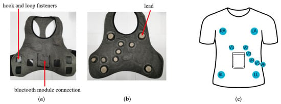
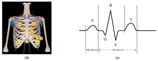
Figure 5.
(a–c) show the basic structure of electrocardiogram, (d) shows the position of human body corresponding to lead of electrocardiogram, and (e) shows ideal electrocardiogram.
The ideal ECG unit (Figure 5e) should have an obvious P wave, T wave and QRS peak. Among them, the P wave represents the point position change caused by atrial systole. The starting point indicates that the excitement reaches from the sinoatrial node to the atrium, and the end point indicates that the atrium has all received the excitement. Its direction is related to its shape and the conduction pathway of the excitement in the atrium. Abnormal P waves indicate lesions or rhythm problems in the atria. The P-R wave interval represents the time required for excitation to pass through the atria, atrioventricular node and atrioventricular bundle to the ventricles. If this is a longer interval it may indicate atrioventricular conduction obstruction. The QRS wave group represents the voltage change when the ventricle is excited. Heart disease may occur if the S-T band is not at the zero line [38]. The movement and state of the human body will affect the ECG [39,40].
3. Results and Discussions
3.1. Air Permeability of Embroidery Fabric Electrode
As shown in Figure 6a, the air permeability of the embroidered fabric electrode is mainly affected by the stitch density of the electrode itself, but it does not completely eliminate the effect of embroidery material itself. Embroidery treatment can significantly reduce the excellent air permeability of the embroidery material itself, but in general, the small area of the embroidery electrode will not have a great impact on the comfort level in terms of air permeability. The air permeability of the electrode of embroidery fabric with a stitch density of 0.2 mm is obviously lower than that of the electrode with a stitch density of 0.3 mm. This results in smaller and fewer air holes on the surface of the embroidery fabric electrode because the stitch density is higher and the yarn is more tightly packed. At the same stitch density, the air permeability will also fluctuate. However, it can be seen from the figure that the permeability of the electrode of embroidery fabric with a 0.3 mm stitch density fluctuates more (within the normal range). This is because the electrical permeability of embroidery fabrics with low stitch density is more affected by embroidery materials.
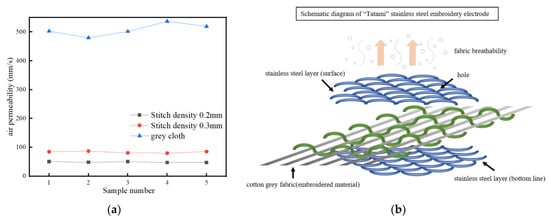
Figure 6.
(a) Air permeability, broken line diagram, (b) electrode structure diagram of embroidery fabric.
The structure of stainless steel embroidery fabric electrode is shown in Figure 6b. Stainless steel yarns are divided into surface lines and bottom lines to form layers of embroidery patterns above and below the cotton grey fabric. Normally, embroidery material is in the state of smooth and tightly stretched in the process of being inwrought, and right now embroidery material can themselves be regarded as roughly even. There is little change in air permeability at each position. In practice, there is a slight difference in the air permeability of each position of embroidery fabric, but it is not enough to be the main factor affecting the air permeability of the electrode of embroidery fabric.
3.2. Fuzzing and Pilling of Embroidery Fabric Electrode
As shown in Figure 7, the fuzzing and pilling performance of the stainless steel embroidery fabric electrode is poor. Compared with the standard of the pilling resistance grade of worsted smooth wool fabric in Figure 8, it can be seen that the pilling grade of stainless steel embroidery fabric electrode is close to the first grade, with a large number of balloons. Stainless steel yarn itself is a blend of polyester filament and stainless steel fiber. But the stainless steel yarn is made up of many short fibers, which can leak a lot of fluff over the surface of the yarn. In the process of embroidery, a computer embroidery machine drop needle speed is very fast. When driving the yarn movement, it will create a certain amount of friction so that on the surface of the stainless steel yarn pile more fluff will leak out. The greater the stitch density of the electrode of the embroidery fabric, the denser the contact between the yarns. While electricity conduction will be better, the friction between the yarns will also increase, causing more fluff to interlock with each other, making the embroidered fabric electrode surface rough. In the experiment of fuzzing and pilling, the performance of the embroidery fabric electrode is not very good, and there is a lot of pilling phenomena on its surface. In actual use, the fabric electrode rubs against human skin and such a pilling effect does not occur. However, the lint on the fabric electrode itself can cause itching.

Figure 7.
State of stainless steel embroidery fabric electrode face after pilling (a). The pilling height of the embroidery fabric electrode was observed from different directions (b). In the process of making an embroidery fabric electrode, the surface of the embroidery fabric electrode is divided into transverse and longitudinal directions because of the directivity of the embroidery needle. The yarn contact mode is different in different directions and the resistance distribution is also different (c).

Figure 8.
Standard sample of pilling resistance rating for worsted smooth wool fabrics.
3.3. Mass Loss of Embroidered Fabric Electrode
In the case of not knowing the number of electrode wear of the embroidery fabric, we chose to test while gradually increasing the number of wear intervals of quality inspection (Figure 9). As shown in Figure 10a, when the total amount of friction was less in the early stage of the experiment, the slope of the mass change curve of the embroidery fabric electrode was larger and the mass loss rate was faster. In the later stage of the experiment, the total amount of friction increases, the slope of the mass change curve decreases obviously, and the speed of mass loss of the embroidery fabric electrode decreases obviously. After 40,000 wear cycles, the average electrode loss rate was 3.4%.
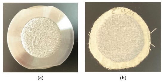
Figure 9.
Sample C after 10,000 frictions (a), sample C after 25,000 frictions (b).
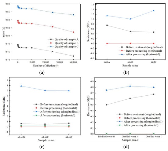
Figure 10.
Embroidery fabric electrode mass loss line chart (a). Figure (b) shows the resistance changes in vertical and horizontal direction of the three embroidery fabric electrode samples after acid sweat treatment. The resistance changes in vertical direction are the largest after acid sweat treatment, which may be due to being out of range or poor contact. Figure (c) shows the changes of electrical resistance in the vertical and horizontal directions of the three embroidery fabric electrode samples after alkaline sweat treatment. The electrical resistance in both directions increases significantly, but the changes are less than those of the electrode samples treated with acidic sweat. Figure (d) shows the vertical and horizontal resistance changes of three stainless steel yarn embroidery fabric electrode samples treated with distilled water. It can be seen that distilled water has little influence on electrode resistance.
As mentioned previously, an inwrought electrocardiogram electrode is in the process that prepares stainless steel yarn and the computer embroidery machine and the yarn in the embroidery material produce friction, which produces a few villi on surface of the electrocardiogram electrode. In the early wear experiment, the villi on the yarn surface in the electrode quickly twisted and knotted with each other, formed small balls and gradually fell off. After this, with the increase of wear times, the villi on the original surface of the embroidery fabric electrode basically formed a ball to fall off. In the wear process, the villi are pulled out from the stainless steel yarn, and then the above process is repeated, and finally, they form a ball and fall off. Therefore, the mass loss in the early stage of the wear experiment is faster. As the first pellets fall off, a process of friction is required to create new fluff on the surface of the fabric electrode, slowing the loss of mass.
3.4. Effect of Sweat on the Embroidered Fabric Electrode
The electrode resistance of embroidery fabric soaked in acid, alkaline sweat and distilled water changed to different degrees respectively (embroidery fabric electrode is directional during embroidery, so the resistance is not uniform, that is, longitudinal and lateral detection resistance is different). Among them, the resistance of the embroidery fabric electrode that reacts with acidic sweat becomes significantly larger (Figure 10b). In the case of fluctuation (there are many contact points in the embroidery fabric electrode, the resistance of the overall electrode has a certain range of fluctuation), its maximum value even exceeds the maximum range of the multimeter. The resistance of the needlework fabric electrode reacting with alkaline sweat also increased obviously (Figure 10c), but it was far less than that of the needlework fabric electrode reacting with acid sweat. The electrode resistance of embroidery fabric reacting with distilled water changed very little and only increased slightly (Figure 10d).
The main reason for this is that stainless steel yarn contains mainly iron. Sweat contains NaCl and water, which can also form a galvanic cell with O2 in the air. After forming Fe2+ with Fe, Fe(OH)3 is further formed, and the water is lost to form rust Fe2O3*nH2O.
4Fe + 6H2O + 3O2 = 4Fe(OH)3
The amount of iron consumed is also different due to the different pH of sweat used in the experiment, which may be one of the reasons for the large difference in the degree of resistance change of the embroidery fabric electrode that reacts with acid base sweat. The electrode resistance of the embroidered fabric that reacted with distilled water changed slightly, probably because the iron in the yarn reacted with water, causing a degree of rust that was much slower than that of acid-based sweat.
3.5. ECG Monitoring Using Embroidery Electrode
The resistance of the embroidery fabric electrode changed in different degrees after the treatment of acid and alkaline sweat. On this basis, ECG signals of embroidery fabric electrodes reacting with acidic sweat, alkaline sweat and distilled water were tested respectively. As shown in the Figure 11, the three groups of electrodes can still receive ECG signals to generate electrocardiogram, and all can see P wave, T wave, QRS peaks required in standard electrocardiogram. However, there were some differences in electrocardiogram among the three groups of samples Among them, the embroidered electrocardiogram electrode that reacts with acidic sweat has obvious difference.

Figure 11.
Figure (a) is an electrocardiogram obtained from an untreated “Tatami” needle electrode with 0.3 mm stitch density of stainless steel embroidery fabric. Figure (b) is an electrocardiogram of a “Tatami” needle electrode with 0.3 mm stitch density of stainless steel embroidery fabric treated with distilled water. Figure (c) is an electrocardiogram of a “Tatami” needle electrode with 0.3 mm stitch density of stainless steel embroidery fabric treated with alkaline sweat. Figure (d) is an electrocardiogram of a “Tatami” needle electrode with 0.3 mm stitch density of stainless steel embroidery fabric treated with acid sweat.
As Figure 11a shows, the electrocardiogram measured using the untreated fabric electrode is very consistent with the standard electrocardiogram. No is burr waveform and baseline fluctuation. The performance of the fabric electrode is still excellent after being treated with distilled water, as shown in Figure 11b. In Figure 11c, after the alkaline sweat treatment, the resistance of the electrode itself increased, and the electrocardiogram measured was still in line with the standard electrocardiogram, but the graph showed fluctuations. The resistance of the fabric electrode treated with acid sweat changed greatly; the fluctuation between the heartbeats was larger, and the P wave or T wave was not obvious in some locations, as shown in Figure 11d.
4. Conclusions
In this work, a needlework fabric electrode has been prepared using a “Tatami” stitch, which showed more contact points between the yarns and an even gap arrangement, which proves it to be a more suitable candidate for the preparation of a needlework fabric electrode. The electrodes of the needlework fabric with 0.2 mm and 0.3 mm stitch spacing for the preparation of “Tatami” stitches using stainless steel yarn have good air permeability and wear resistance, which allows comfort of the human body. In the process of daily close-fitting wear, this kind of electrode will contact and react with sweat secreted on the surface of human skin for a long time, which will cause some damage to the electrode. However, it will not affect the function of the stainless steel embroidered fabric electrode too much, and it turns out that the stainless steel embroidered fabric electrode can still measure the ECG signal of the human body after an adequate reaction with sweat, generating a standard electrocardiogram. The development and improvement of a new flexible electrode have broad prospects in wearable devices for human health monitoring. At present, people pay more attention to their health status, and the development of flexible electrodes becomes very important when the ECG market is just being developed.
Compared with the Ag/AgCl electrodes commonly used in cardiac electrical testing, the embroidered fabric electrodes have better air permeability and are more comfortable in use, although they are somewhat prone to pilling. It fits the skin completely and can be reused many times. It is more suitable for long-term and comfortable ECG detection (Table 2).

Table 2.
Comparison between stainless steel yarn embroidery fabric electrode and traditional Ag/AgCl wet electrode.
Moreover, a stainless steel embroidery fabric electrode has great advantages in production cost and production process. The development and improvement of the embroidered fabric electrode is of great significance to the research of wearable electrodes. The fly in the ointment is that there are more short fibers in stainless steel blended yarn, which may make users feel itchy during wearing, which still needs to be studied and improved. In future work and experiments, the following points can be considered to further improve the comfort of stainless steel embroidery electrodes. First, improve the yarn, such as making stainless steel filament or combining stainless steel yarn with other yarns to design new yarns. Second, improve the post-processing. For example, the surface coating is carried out after the fabric electrode is prepared.
Author Contributions
T.W., Y.J. and X.X. discussed the idea and planning of the experiment. Y.J. and X.X. prepared some experimental instruments and gave instructions. T.W. completed the preparation of all samples for the experiment. T.W. completed the experimental operation and data recording. T.W., X.X. and Y.J. conducted data analysis. T.W. prepared the manuscript of the paper and all the drawing and shooting of the images. A.W. did grammar proofreading of the English manuscript. All authors have read and agreed to the published version of the manuscript.
Funding
The Project “Fibre materials and products for emergency support and public safety” from Jiangsu New Horizon Advanced Functional Fibre Innovation Centre Co. Ltd. (Grant No. 2022-rw0307): 2022-rw0307.
Data Availability Statement
Not applicable.
Acknowledgments
To complete this paper, I firstly thank my supervisor, Yun Jiang, for his help and support in my study. Thanks to Xueliang Xiao for providing part of the experimental equipment and operation guidance. I would like to thank the two people for their guidance on my thesis writing and grammar and my friends and family for their support and companionship.
Conflicts of Interest
The authors declare no conflict of interest.
References
- Cho, H.; Lee, J.H. A Study on the Optimal Positions of ECG Electrodes in a Garment for the Design of ECG-Monitoring Clothing for Male. J. Med. Syst. 2015, 39, 95. [Google Scholar] [CrossRef] [PubMed]
- Zetterström, R. Nobel Prize to Willem Einthoven in 1924 for the discovery of the mechanisms underlying the electrocardiogram (ECG). Acta Paediatr. 2009, 98, 1380–1382. [Google Scholar] [CrossRef] [PubMed]
- D’Ascenzi, F.; Sciaccaluga, C.; Cameli, M.; Cecere, A.; Ciccone, M.M.; Di Francesco, S.; Ganau, A.; Imbalzano, E.; Liga, R.; Palermo, P.; et al. When should cardiovascular prevention begin? The importance of antenatal, perinatal and primordial prevention. Eur. J. Prev. Cardiol. 2019, 28, 361–369. [Google Scholar] [CrossRef] [PubMed]
- Şahin, B.; Ilgün, G. Risk factors of deaths related to cardiovascular diseases in World Health Organization (WHO) member countries. Health Soc. Care Community 2020, 30, 73–80. [Google Scholar] [CrossRef]
- Yang, J.G.; Gu, H.Q.; Jian, B.O.; Yang WA, N.G.; Wei, L.I. Regional Variations in Medication Usage for Cardiovascular Diseases at the Community Level in China (PURE-China Study). Biomed. Environ. Sci. 2017, 30, 450–454. [Google Scholar] [CrossRef]
- Soroudi, A.; Hernández, N.; Berglin, L.; Nierstrasz, V. Electrode placement in electrocardiography smart garments: A review. J. Electrocardiol. 2019, 57, 27–30. [Google Scholar] [CrossRef]
- Zaman, S.U.; Tao, X.; Cochrane, C.; Koncar, V. Smart E-Textile Systems: A Review for Healthcare Applications. Electronics 2021, 11, 99. [Google Scholar] [CrossRef]
- Hernández, A.I.; Carrault, G.; Mora, F.; Bardou, A. Overview of carmem: A new dynamic quantitative cardiac model for ECG monitoring and its adaptation to observed signals. Acta Biotheor. 2000, 48, 303–322. [Google Scholar] [CrossRef]
- Yun, M.-H.; Yeon, J.-W.; Hwang, J.; Hong, C.S.; Song, K. A calibration technique for an Ag/AgCl reference electrode utilizing the relationship between the electrical conductivity and the KCl concentration of the internal electrolyte. J. Appl. Electrochem. 2009, 39, 2587–2592. [Google Scholar] [CrossRef]
- Merritt, C.R.; Troy Nagle, H.; Grant, E. Fabric-Based Active Electrode Design and Fabrication for Health Monitoring Clothing. IEEE Trans. Inf. Technol. Biomed. Publ. IEEE Eng. Med. Biol. Soc. 2009, 13, 274–280. [Google Scholar] [CrossRef]
- Popović-Maneski, L.; Ivanovic, M.; Atanasoski, V.; Miletić, M.; Zdolšek, S.; Bojović, B.; Hadzievski, L. Properties of different types of dry electrodes for wearable smart monitoring devices. Biomed. Eng. Biomed. Tech. 2020, 65, 405–415. [Google Scholar] [CrossRef]
- Dong, L.; Xu, C.; Li, Y.; Huang, Z.-H.; Kang, F.; Yang, Q.-H.; Zhao, X. Flexible electrodes and supercapacitors for wearable energy storage: A review by category. J. Mater. Chem. A 2016, 4, 4659–4685. [Google Scholar] [CrossRef]
- Li, X.; Sun, Y. A wearable button-like system for long-term multiple biopotential monitoring using non-contact electrodes. Smart Health 2018, 11, 2–15. [Google Scholar] [CrossRef]
- Saadatnia, Z.; GhaffariMosanenzadeh, S.; Chin, M.M.; Naguib, H.E.; Popovic, M.R. Flexible, Air Dryable, and Fiber Modified Aerogel-Based Wet Electrode for Electrophysiological Monitoring. IEEE Trans. Biomed. Eng. 2020, 68, 1820–1827. [Google Scholar] [CrossRef]
- Yu, Z.; Tang, Y.; Cai, G.; Ren, R.; Tang, D. Paper Electrode-Based Flexible Pressure Sensor for Point-of-Care Immunoassay with Digital Multimeter. Anal. Chem. 2018, 91, 1222–1226. [Google Scholar] [CrossRef]
- Liu, H.; Zhao, G.; Wu, M.; Liu, Z.; Xiang, D.; Wu, C.; Cheng, Y.; Wang, H.; Wang, Z.L.; Li, L. Ionogel infiltrated paper as flexible electrode for wearable all-paper based sensors in active and passive modes. Nano Energy 2019, 66, 104161. [Google Scholar] [CrossRef]
- Zhang, J.; Dong, L.; Xu, C.; Hao, J.; Kang, F.; Li, J. Comprehensive approaches to three-dimensional flexible supercapacitor electrodes based on MnO2/carbon nanotube/activated carbon fiber felt. J. Mater. Sci. 2017, 52, 5788–5798. [Google Scholar] [CrossRef]
- Chen, G.; Wang, W.; Lu, X.; Mugaanire, I.T.; Zhang, Y.; Ai, Y.; Zhu, M. Homogeneous intercalated graphene/manganic oxide hybrid fiber elec-trode assembly by non-liquid-crystal spinning for wearable energy storage. Mater. Sci. Technol. 2022, 97, 1–9. [Google Scholar] [CrossRef]
- Frydrysiak, M. Comparison of Textile Resistive Humidity Sensors Made by Sputtering, Printing and Embroidery Techniques. Fibres Text. East. Eur. 2020, 28, 91–96. [Google Scholar] [CrossRef]
- Liu, Z.; Zhai, Y.; Liu, X. Progress on fabric electrodes used in biological signal acquisition. In Proceedings of the Shanghai Textile and Garment Innovation Postgraduate Academic Forum and the 9th International Forum on Textile and Garment Innovation, Shanghai, China, 10–12 July 2015; pp. 163–168. [Google Scholar]
- Pola, T.; Vanhala, J. Textile Electrodes in ECG Measurement. In Proceedings of the 2007 International Conference on Intelligent Sensors, Sensor Networks and Information Processing (ISSNIP 2007), Melbourne, VIC, Australia, 3–6 December 2007; pp. 635–639. [Google Scholar]
- Zhou, Y.; Ding, X.; Zhang, J.; Duan, Y.; Hu, J.; Yang, X. Fabrication of conductive fabric as textile electrode for ECG monitoring. Fibers Polym. 2014, 15, 2260–2264. [Google Scholar] [CrossRef]
- Qin, T.; Peng, S.; Hao, J.; Wen, Y.; Wang, Z.; Wang, X.; He, D.; Zhang, J.; Hou, J.; Cao, G. Flexible and Wearable All-Solid-State Supercapacitors with Ultrahigh Energy Density Based on a Carbon Fiber Fabric Electrode. Adv. Energy Mater. 2017, 7, 1700409. [Google Scholar] [CrossRef]
- Zhang, D.; Zhang, X.; Chen, Y.; Wang, C.; Ma, Y. An environment-friendly route to synthesize reduced graphene oxide as a supercapacitor electrode material. Electrochim. Acta 2012, 69, 364–370. [Google Scholar] [CrossRef]
- Li, Z.; Chu, J.; Yang, C.; Hao, S.; Bissett, M.A.; Kinloch, I.A.; Young, R.J. Effect of functional groups on the agglomeration of graphene in nanocomposites. Compos. Sci. Technol. 2018, 163, 116–122. [Google Scholar] [CrossRef]
- Ankhili, A.; Tao, X.; Cochrane, C.; Koncar, V.; Coulon, D.; Tarlet, J.-M. Ambulatory Evaluation of ECG Signals Obtained Using Washable Textile-Based Electrodes Made with Chemically Modified PEDOT:PSS. Sensors 2019, 19, 416. [Google Scholar] [CrossRef]
- Zhao, J.; Li, X.; Li, X.; Cai, Z.; Ge, F. A flexible carbon electrode based on traditional cotton woven fabrics with excellent capacitance. J. Mater. Sci. 2017, 52, 9773–9779. [Google Scholar] [CrossRef]
- Lv, J.; Zhang, L.; Zhong, Y.; Sui, X.; Wang, B.; Chen, Z.; Feng, X.; Xu, H.; Mao, Z. High-performance polypyrrole coated knitted cotton fabric electrodes for wearable energy storage. Org. Electron. 2019, 74, 59–68. [Google Scholar] [CrossRef]
- Lee, B.-M.; Eom, J.-J.; Baek, G.Y.; Hong, S.-K.; Jeun, J.-P.; Choi, J.-H.; Yun, J.M. Cellulose non-woven fabric-derived porous carbon films as binder-free electrodes for supercapacitors. Cellulose 2019, 26, 4529–4540. [Google Scholar] [CrossRef]
- Liu, H.; Tang, D.; Hu, Y.; Xu, L.; Song, J.; Wang, W.; Cheng, B. The effect of chlorine/argentum atomic ratios on electrochemical behaviors and signal acquisition abilities of embroidered electrodes for bio-potential signal measurement. Appl. Phys. A 2019, 125, 501. [Google Scholar] [CrossRef]
- Hu, Y. Design and Application of Flexible Textile Electrode for Bioelectrical Signal Measurement. Master’s Thesis, Tianjin Polytechnic University, Tianjin, China, 2018. [Google Scholar]
- Yuan, H. Research on Textile-structured Ag-AgCl ECG Electrodes. Master’s Thesis, Xi’an Polytechnic University, Xi’an, China, 2015. [Google Scholar]
- Ding, H.; Sarela, A.; Helmer, R.; Mestrovic, M.; Karunanithi, M. Evaluation of Ambulatory ECG Sensors for a Clinical Trial on Outpatient Cardiac Rehabilitation. In Proceedings of the 2010 IEEE/ICME International Conference on Complex Medical Engineering, Gold Coast, QLD, Australia, 13–15 July 2010; pp. 240–243. [Google Scholar]
- Das, A.; Krishnasamy, J.; Alagirusamy, R.; Basu, A. Analysis of the electromagnetic shielding behavior of stainless steel filament and PET/SS hybrid yarn incorporated conductive woven fabrics. Fibers Polym. 2014, 15, 2423–2427. [Google Scholar] [CrossRef]
- Zhang, H.; Yao, C.; Qin, X. A Visually Observable Copper Ion Adsorption Membrane by Electrospinning Combined with Copper Ion Probe. Fibers Polym. 2021, 22, 1844–1852. [Google Scholar] [CrossRef]
- Daukantienee, V.; Laurinaviciutee, I. The synergism of design and technology for the optimisation of embroidery motifs in clothing. Int. J. Cloth. Sci. Technol. 2013, 2, 350–360. [Google Scholar] [CrossRef]
- Anderson, K.M. Machine Embroidery: Tools, Techniques and Technologies. AATCC Rev. 2005, 5, 27–30. [Google Scholar]
- Mar, P.L.; Van Tuyl, J.S.; Lim, M.J. Basic surface electrocardiogram interpretation for the pharmacist. Am. J. Health Pharm. 2021, 78, 850–861. [Google Scholar] [CrossRef] [PubMed]
- Li, X.; Cao, J.; Li, H.; Yu, P.; Fan, Y.; Xiao, Y.; Yin, Y.; Zhao, X.; Wang, Z.L.; Zhu, G. Differentiation of Multiple Mechanical Stimuli by a Flexible Sensor Using a Dual-Interdigital-Electrode Layout for Bodily Kinesthetic Identification. ACS Appl. Mater. Interfaces 2021, 13, 26394–26403. [Google Scholar] [CrossRef]
- Cao, J.; Liang, F.; Li, H.; Li, X.; Fan, Y.; Hu, C.; Yu, J.; Xu, J.; Yin, Y.; Li, F.; et al. Ultra-robust stretchable electrode for e-skin: In situ assembly using a nanofiber scaffold and liquid metal to mimic water-to-net interaction. InfoMat 2022, 4, e12302. [Google Scholar] [CrossRef]
Publisher’s Note: MDPI stays neutral with regard to jurisdictional claims in published maps and institutional affiliations. |
© 2022 by the authors. Licensee MDPI, Basel, Switzerland. This article is an open access article distributed under the terms and conditions of the Creative Commons Attribution (CC BY) license (https://creativecommons.org/licenses/by/4.0/).
