Abstract
To significantly improve the electronic efficiency of coaxial multi-beam relativistic klystron amplifier (CMB-RKA), the physical process of beam-wave interaction and parameters that affect efficiency was studied. First, the high efficiency of beam-wave interaction was discussed by simulating the efficiency versus the parameters (frequency of cavity, drift tube length between cavities, and external quality factor of output cavity), in the one-dimensional (1-D) large-signal simulation software. Moreover, the further physical process of beam-wave interaction was analyzed through simulating the current modulation factor and the number of particles at the entrance of the output cavity, in the three-dimensional (3-D) particle in cell simulation software. Last, with the optimal parameters in 3-D simulations, the CMB-RKA, which has 14 electron beams with a total current of 4.2 kA (14 × 300 A), can generate an output power of 1.02 GW with a saturation gain of 55.6 dB and an efficiency of 48.7%, when beam voltage is 500 kV, which indicated the CMB-RKA can achieve high efficiency for high-power microwave radiation.
1. Introduction
Relativistic klystron amplifier (RKA) is one of the promising high-power microwave (HPM) sources and is widely used in high-power radars, new accelerators, and new communication systems, because of its advantages in high-power, high-efficiency, stable-phase, and stable-amplitude of output power [1,2,3]. It has achieved an output power of 100 MW to several GW from the L-band to the Ka-band [4,5,6,7,8,9,10], and it is easy to obtain high radiation power in the low-frequency band, such as the 15-GW L-band RKA developed by Friedman et al. at the US Naval Laboratory [4].
After decades of development, RKA no longer pursues power improvement but focuses on miniaturization, high efficiency and low power consumption [11]. The high efficiency of RKA can reduce the volume and consumption of pulsed power sources, which is conducive to the miniaturization, stability, and reliability of the HPM system. Therefore, theoretical and experimental research on the physical mechanism of high-efficiency beam-wave interaction is regarded as a high priority in the future. At the same time, High-Efficiency International Klystron Activity (HEIKA) was established internationally driven by the next generation of large particle accelerators, such as Compact Linear Collider [12], Future Circular Collider [13], and International Linear Collider. Under the promotion of HEIKA, a series of methods to improve efficiency was proposed, such as Core Oscillation Method (COM) [14], Bunching-Alignment-Collecting (BAC) [15], Cluster Center Stabilization Method (CSM) [16], Two-Stage Structure [17], etc. The essence of these methods is to achieve a core of the electron beam whose electron phases are the same, which leads to improvement in the efficiency of beam-wave interaction. Baikov A. Y. predicted that the RF electronic efficiency can be 90% by the COM method in theory [14], and the efficiency in MAGIC 2D simulation increased from the original 82.7% up to 84.6% by the COM method in high-power klystron amplifier [18]. However, for a relativistic klystron amplifier driven by intense electron beams, its electronic efficiency is limited to about 40%, because of strong space-charge forces [19,20].
In this paper, we investigate the physical mechanism of high-efficiency beam-wave interaction based on a five cavities coaxial multi-beam relativistic klystron amplifier (CMB-RKA), in which (i) the perveance is reduced by the multi-beam to improve efficiency; (ii) the fundamental-mode coaxial cavity enhances the characteristic impedance (R/Q) and coupling coefficient (M) to achieve high-efficiency beam-wave interaction. Moreover, the parameters affecting the beam-wave interaction, which are high-frequency parameters, structural parameters, and operating parameters of CMB-RKA, are studied through one-dimensional (1-D) and three-dimensional (3-D) simulations. They are adopted to the design of the CMB-RKA. As a result, the 1.02 GW output power is achieved, corresponding with an efficiency of 48.7% and a saturation gain of 55.6 dB. It is believed that the presented results would be of great interest to the design and development of high-efficiency RKA.
2. Physical Design
The structure of CMB-RKA is shown in Figure 1, and its operating principle can be described as follows. An RF input signal injects into the input cavity to excite an operating mode. The intense relativistic electron beams are slightly velocity modulated across the gap of the input cavity. Then, the beams are density-modulated in the drift tubes to present bunching core and peripheral electrons. In addition, the velocity is modulated again by the idler cavities, which benefits to push peripheral electrons into the bunch. Last, as the beams travel down the drift tubes and the idler cavities to the output cavity, the electrons are decelerated with converting their kinetic power into RF power. The efficiency depends on the modulated current exciting, which is closely related to the electron beams and cavities. Thus, the physical design is developed first, including the parameters of electron beam and cavities.
Figure 1.
y-z sectional view of the S-band CMB-RKA.
2.1. Design of Electron Beam Parameters
In klystron, the electronic efficiency is defined as [21]
In Equation (1), , , are the power, voltage, current of the electron beam, respectively; , , are the nth harmonic power, voltage, current of the modulated electron beam, respectively. and can be expanded by a cosine function, and the factor 1/2 comes from the time average of the square of the cosine function in an RF cycle. Usually, the current modulation factor is defined as . When is 2, the efficiency is 100%, which means the density of modulated beam is well represented as a function. However, other factors should be considered, such as space-charge force, to counteract the beam bunching, which leads that the efficiency cannot reach a theoretical 100%. Generally, the space-charge force is characterized directly by perveance () [14], and Ref. [22] indicates that the efficiency is growing with a reduction of perveance. Thus, to obtain high efficiency, perveance should be small for a single electron beam.
Additionally, the multi-beam klystron uses several metal wall-separated channels to prevent communication between electron beams so that the operating voltage can be reduced significantly [23]. This means low perveance and miniaturized devices. Consequently, the structure of the multi-beam is the best option for high efficiency. The efficiency was calculated by perveance in MBK, as shown in the equation () [24], where the unit of perveance P is K, and the maximum efficiency can be 78%. Here, we propose a CMB-RKA with 14 beamlets of 500 kV and 300 A. The perveance of a beamlet is 0.85 K and the total perveance of the multi-beam electron beam is 11.9 K, where the theoretical efficiency of the CMB-RKA is 64.4%.
2.2. Design of Cavity Parameter
Multiple cavities are adopted to achieve high gain and high efficiency. In addition, Ref [14] researched the maximal efficiency of two multi-beam klystrons (7-beams and 42-beams) that their efficiency all increased non-linearly as the number of cavities increased. When the number of cavities is greater than 5, the efficiency increases slowly. Therefore, we set the number of cavities to be 5. The fundamental mode of the coaxial resonant cavity is adopted in the CMB-RKA, as shown in Figure 1. The effects of structural parameters (, , , and ) of the cavity on high-frequency parameters (M, f, and ) are simulated in 3-D EM analysis software(CST Studio Suite) [25], and the results are shown in Figure 2. We can adjust the structural parameters to obtain the appropriate high-frequency parameters, which can be used in 1-D and 3-D simulations.
Figure 2.
Frequency (f), coupling coefficient (M), and characteristic impedance () of the cavity as functions of (a) axial length of the cavity (), (b) gap length of the cavity (), and (c) Rout when is a constant.
In addition, the equivalent circuit of the coaxial resonant cavity is an RLC circuit, as shown in Figure 3a. L and C represent the high-frequency characteristics of the toroidal and parallel-plate portion in the cavity, R represents the electronic beam load, external load, and cavity wall loss. When the operating frequency is smaller than the frequency of the cavity, the circuit is inductive, therefore the phase of V will lag behind the phase of [26]. Figure 3b shows the situation where the phase difference () between the gap voltage of cavity (V) and the electron current () is 90°, whose electron beams is under a sinusoidal perturbation. In this case, fast-velocity electrons are decelerated, and slow-velocity electrons are accelerated by gap voltage (V) so that the peripheral electrons can be pushed into the bunching core. Thus, the detuning cavity operating in fundamental mode is applied to bunch peripheral electrons and obtain the high efficiency of the device.
Figure 3.
(a) Equivalent circuit of the fundamental-mode coaxial cavity. (b) Electron current () and gap voltage of cavity (V) under a sinusoidal perturbation (Electrons in point A is in the electron bunching core, Electrons in point B is fast-velocity electrons, and Electrons in point C is slow-velocity electrons.).
3. Beam-Wave Interaction
The efficiency of a klystron is determined by a set of parameters that can be divided into two groups. The parameters in the first group are beam voltage, beam current, number of beams, injection power, and operating frequency. The parameters in the second group are , M, and frequency of the cavity (), external quality factors of the input and output cavities (), number of the cavity and drift tube length between the cavities (). In this section, the high-efficiency of beam-wave interaction was discussed by some parameters of these, in 1-D large-signal numerical simulation software (AJDISK) and 3-D particle in cell (PIC) simulation software (CHIPIC).
3.1. 1-D Large-Signal Research on the Physical Process of Beam-Wave Interaction
AJDISK is a 1-D large-signal numerical simulation software developed at SLAC and based on the disc model, which is adapted to simulate klystrons with a single cylindrical and sheet beam [27]. Thus, when it was used to analyze the high-efficiency beam-wave interaction of CMB-RKA, the equivalent must be done. In AJDISK simulation, the is 14 times the CMB-RKA and the beam current is 300 A that 1/14 times the CMB-RKA, the other parameters, such as M, beam voltage, , beam radius, drift tube radius, input power, , and , keep the same with the CMB-RKA. Moreover, the single variable method was taken in the whole process of the research. It means that only one parameter was changed whereas the others were fixed.
3.1.1. Effect of Cavity Frequency on Beam-Wave Interaction
According to Section 2.2, the detuning cavities can help the peripheral electrons move into the bunching core. That is because the phase difference between the gap voltage of the cavity and the modulation electron current increases with the frequency of the cavity. As a result, a weak velocity modulation of electrons within the bunching core can be, but the antibunching electrons. And the bunching core will oscillate for the space-charge force and the weak velocity modulation so that the antibunching electrons will be kicked into the bunching core due to a stronger velocity modulation. Thus, for high efficiency, the initial bunching core must be generated first, by the cavities that their frequency are near the operating frequency, and the collecting with the peripheral electrons is later by the detuning cavities. As shown in Figure 4, and are near the operation frequency, and obviously increases, especially, increase to hundreds of MHz comparing the operating frequency. It indicates that the input cavity and cavity 2 play the main role on producing the initial bunching core, and the peripheral electrons are gathered at the bunching core by cavity 3 and 4 dominantly. Moreover, the frequency of the output cavity acting a decelerated structure is near the operating frequency.
Figure 4.
Efficiency versus frequency of the cavity (, , , , are frequency of the input cavity, cavity 2, cavity 3, cavity 4, and output cavity, respectively.).
Furthermore, the effective range of cavity frequency is different. As shown in Figure 4, the frequency range of the cavity 2 is minimum, and the frequency range of the cavity 4 is maximum. Therefore, the frequency of the cavity 2 cannot deviate too much in design and experiment. On the other hand, the frequency of the input cavity should be stabilized at the design frequency of 2.88 GHz because the electron beams entering the input cavity are uniform.
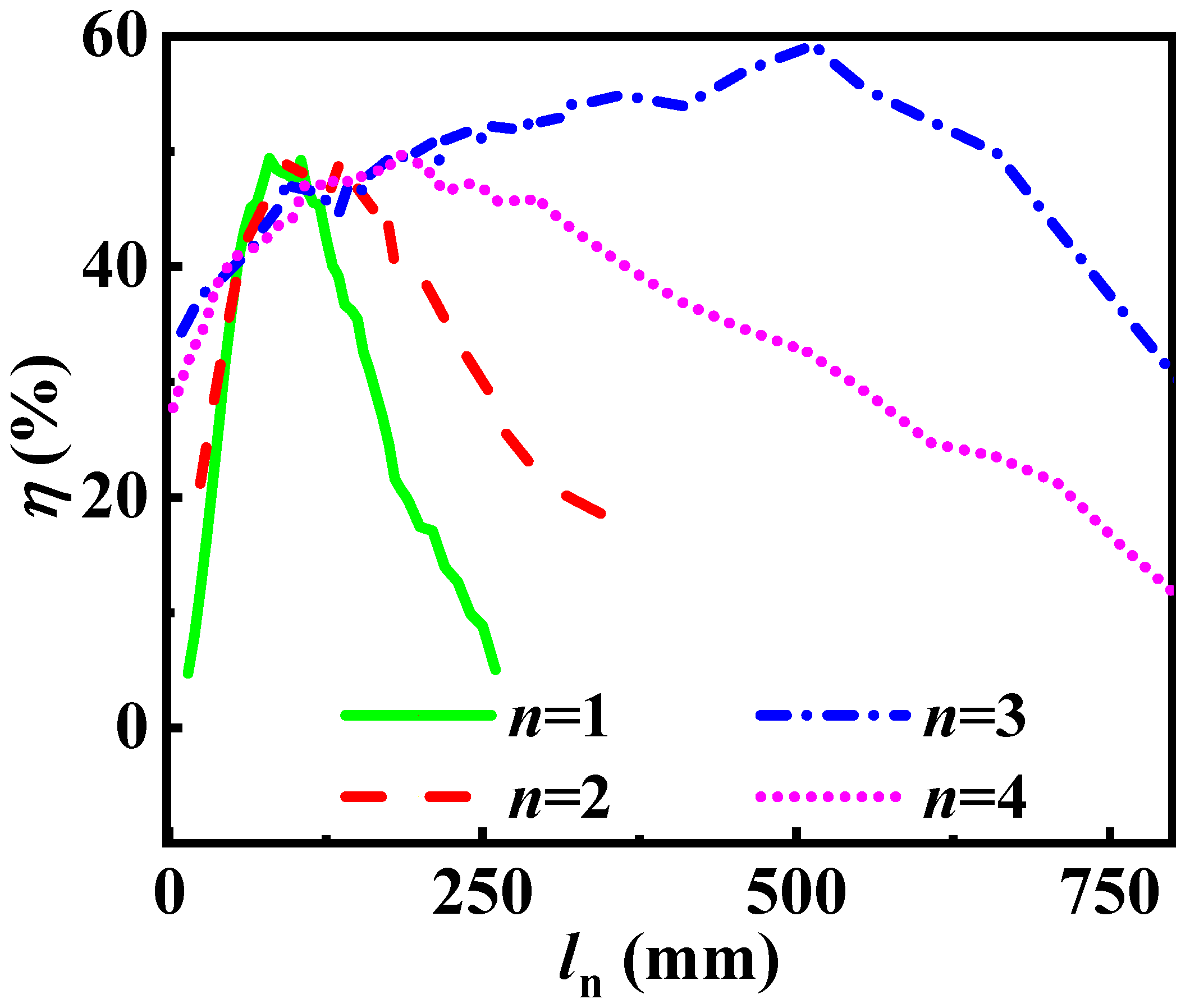
3.1.2. Effect of the Drift Tube Length between Cavities on Beam-Wave Interaction
According to Section 3.1.1, the input cavity and cavity 2 play the main role in producing the initial bunching core, thus drift tube length I () and II () are relatively short (Figure 5). Furthermore, as the generation of the initial bunching core, the density of charge within the bunching core increases, and the space-charge force will start to push the electrons away from the bunching core. Results that the bunch electrons will travel non-monotonic toward the bunching core, and the antibunching electrons without the debunching space-charge force will travel monotonic toward the bunch. This is beneficial to high efficiency, but it requires a substantial increase in the drift tube length of the later stage. As shown in Figure 5, drift tube length III () and IV () is longer. In particular, when drift tube length III () is 550 mm, the efficiency can be close to 60%.
Figure 5.
Efficiency versus drift tube length (, , and , are the drift tube length I, II, III, IV, respectively.).
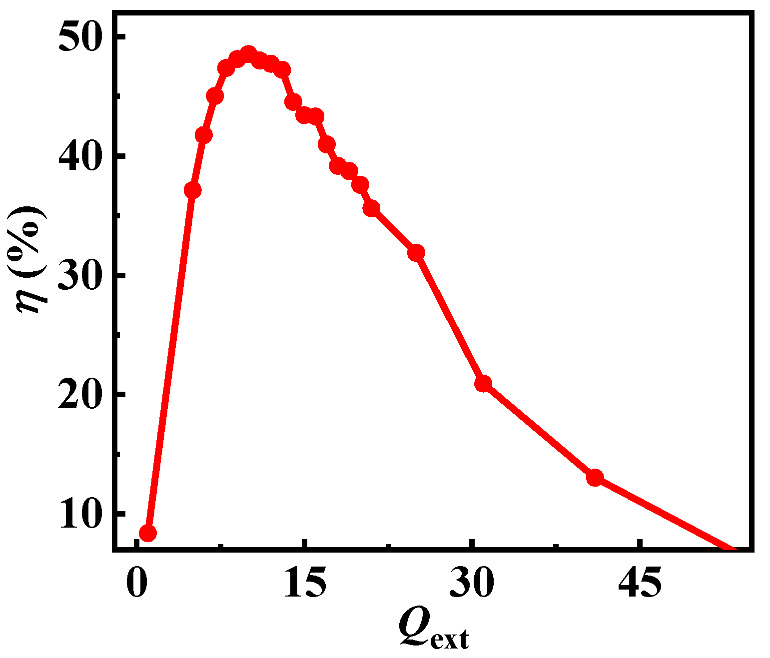
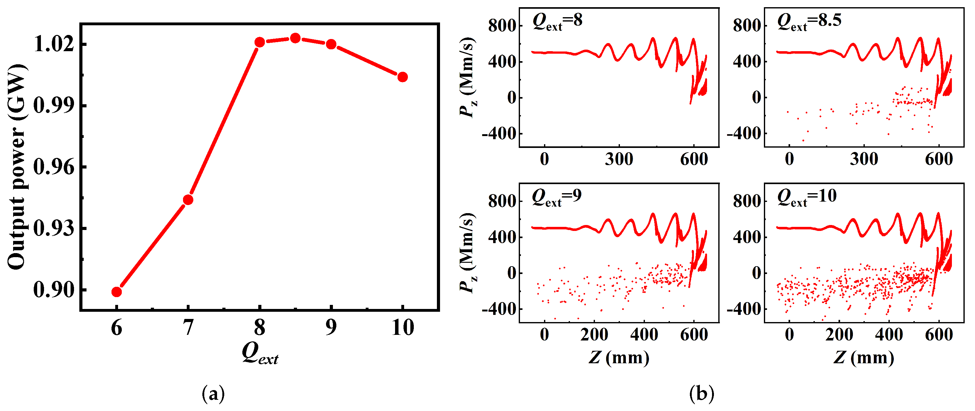
3.1.3. Effect of the of the Output Cavity on Beam-Wave Interaction
In the output cavity, the was used to describe its coupling with the external coupler waveguide, and relate closely to its gap voltage to decelerate the modulated electrons sufficiently. Generally, the gap voltage of the output cavity is roughly equivalent to the beam voltage when the electron beam is well-modulated. If the gap voltage is too high the partial beams will turn around, resulting in a decline in the efficiency. Therefore, it is necessary to find an appropriate of the output cavity to obtain a high efficiency. As shown in Figure 6, the best of the output cavity is 10, and its range is very limited.
Figure 6.
Efficiency versus of the output cavity.
3.2. 3-D Pic Research on the Physical Process of Beam-Wave Interaction
In Section 3.1, we obtain the key parameters that affect the efficiency; however, the further physical process is not present from those parameters. The 3-D PIC simulation is more in line with the actual model of CMB-RKA and the software we used is CHIPIC which was developed at the University of Electronic Science and Technology of China and was proved a validity electromagnetic PIC code [28]. It can clearly analyze the bunching process of the electron beam and the physical nature of the high-efficiency beam-wave interaction. In this section, we investigate the effect of the frequency of cavity 2 () and the drift tube length III () on the beam bunching, by observing and analyzing the nth (n = 1, 2, 3) harmonic current (, , ) of modulated beam and the number of particles at the entrance of the output cavity.
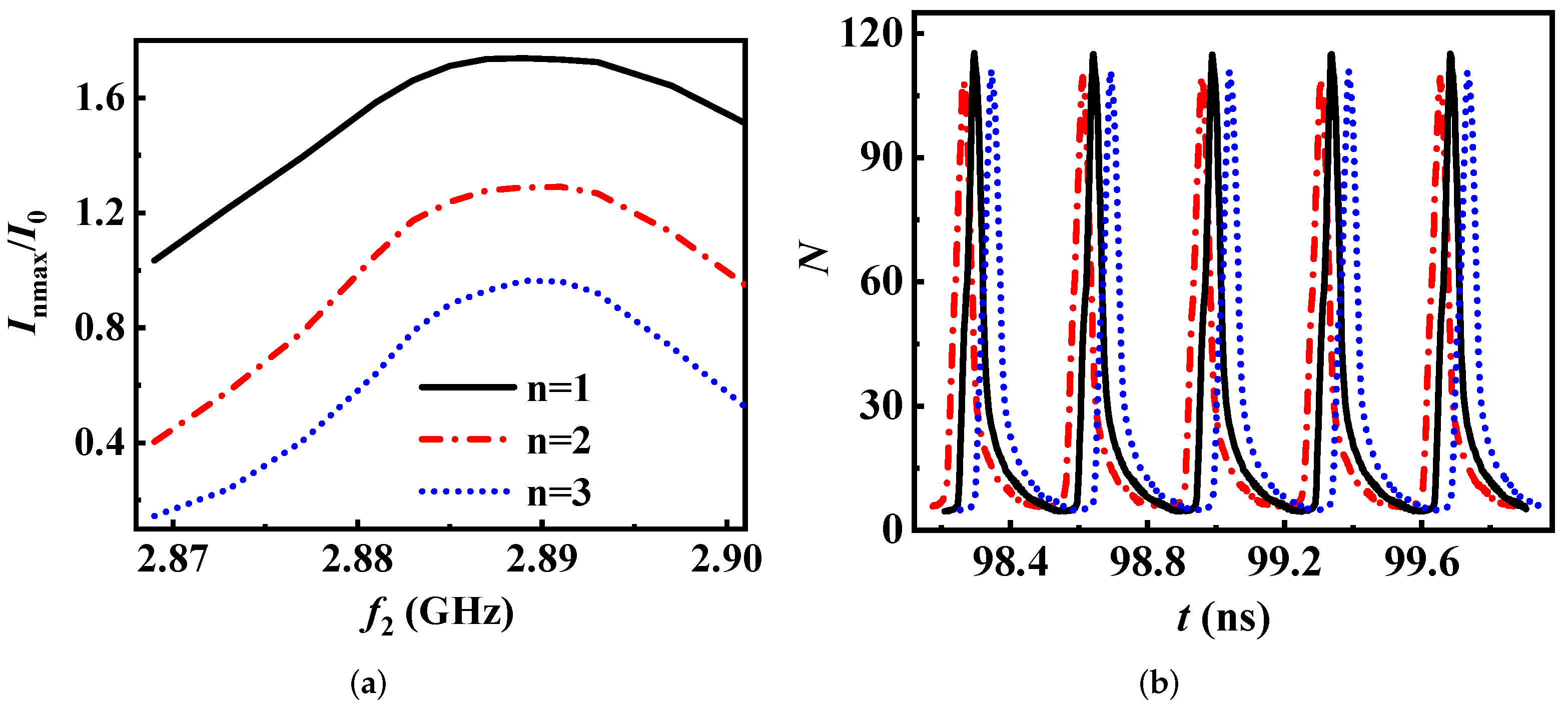
3.2.1. Effect of the Frequency of the Cavity 2 on Beam-Wave Interaction
From Section 3.1, it is known that the frequency of the cavity 2 () should be near the operating frequency, and its range is very limited. In this section, we simulated the modulation current (, n = 1, 2, 3) and the number of particles (N) at the entrance of the output cavity in 3-D PIC. It should be noted that N is physical particles within each macroparticle in CHIPIC. Additionally, the analysis of (n = 1, 2, 3) and N is illustrated in Figure 7. In Figure 7a, the first harmonic maximum current modulation factor () is over 1.6 as increases from 2.885 to 2.893 GHz, and the changes in (n = 2, 3) coincide well with . This suggests that the beam-wave interaction efficiency is high within this range of . In Figure 7b, N is largest when is 2.889 GHz, proving that the peripheral electrons kicked into the bunching core is the most. Consequently, for the CMB-RKA, the frequency of the cavity 2 is 2.889 GHz and is 1.78 respectively.
Figure 7.
(a) Maximum current modulation factor versus frequency of the cavity 2 ( is the maximum modulation current of the nth harmonic, n = 1, 2, 3.). (b) Number of particles at the entrance of the output cavity ( of short dash dot line is 2.885 GHz, of solid line is 2.889 GHz, of short dot line is 2.893 GHz.).
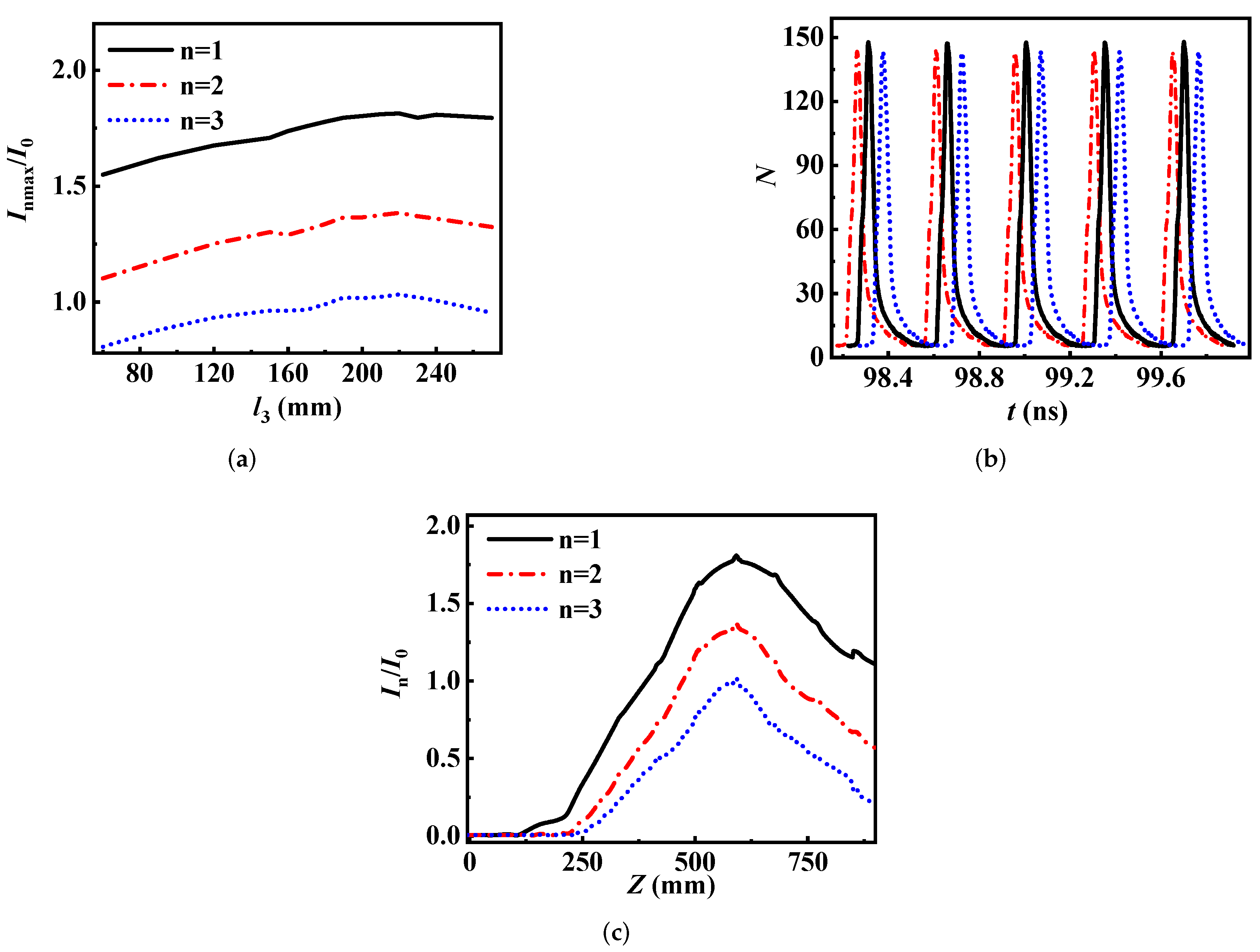
3.2.2. Effect of the Drift Tube Length III on Beam-Wave Interaction
After the velocity modulation in the first of three cavities and the density modulation in the drift tube, the bunching core has been formed. To improve beam-wave interaction efficiency, the drift tube length III () should be long enough to collect the peripheral electrons. When is from 180 to 240 mm, is over 1.75, and the changes in (n = 2, 3) coincide well with (Figure 8a). In addition, N is largest when is 210 mm (Figure 8b). Therefore, the drift tube length III () is 210 mm and is 1.81, respectively. Figure 8c shows the distribution of the modulation current along the z-axis. When Z = 591 mm, (n = 1, 2, 3) is the largest. Hence, we can set the output cavity at Z = 591 mm to obtain the highest RF power.
Figure 8.
(a) Maximum current modulation factor versus drift tube length III ( is the maximum modulation current of the nth harmonic, n = 1, 2, 3). (b) Number of particles at the entrance of the output cavity ( of short dash dot line is 180 mm, of solid line is 210 mm, of short dot line is 240 mm). (c) Current modulation factor along the length of the CMB-RKA.
4. Application in S-Band CMB-RKA
After 1-D and 3-D calculations, we select some high-efficiency parameters which are shown in Table 1, and the corresponding efficiency in 1-D is 52%. According to the parameters, the 3-D model of CMB-RKA was established in the CHIPIC (Figure 1), and the operation mode of its cavity is TM. In the simulation, we validate the application of the above investigations and design a high-efficiency CMB-RKA for HPM radiation at S-band.
Table 1.
Parameters of 1-D calculation.
The of the output cavity is closely related to the extraction of output microwave energy, and there is an optimal value (Figure 9). As of the output cavity increases, the number of electrons that run back towards the negative z-axis increases, leading to a decrease in output power. Consequently, the of the output cavity is set as 8.
Figure 9.
(a) Output power versus the of the output cavity. (b) Axial momentum of the electrons along the length of the CMB−RKA.
Due to the difference in the algorithms adopted by AJDISK and CHIPIC, the saturation gain of the device will be different. It is necessary to simulate the saturation gain of S-band CMB-RKA at different input power through CHIPIC. As shown in Figure 10, the output power becomes saturated when the input power is 2.8 kW. If the input power increases, electrons turn around seriously in the output cavity, causing a decrease in the output power (Figure 10). Thus, the input power is taken as 2.8 kW, corresponding saturation gain of 55.6 dB, and the efficiency of 48.7%. Comparing the efficiency between 1-D and 3-D, the difference is only 3%, which proves that the results of the 1-D large-signal simulation are credible.
Figure 10.
(a) Output power and gain versus input power. (b) Axial momentum of the electrons along the length of the CMB−RKA.
After optimization, the waveform of output power is shown in Figure 11. The output power and efficiency are 1.02 GW and 48.7%, respectively, indicating that the S-band CMB-RKA can operate stably with high efficiency.
Figure 11.
Output power waveform.
5. Conclusions
For high electronic efficiency, the 1-D software AJDISK and the 3-D software CHIPIC are adopted to study the beam-wave interaction mechanism of the S-band CMB-RKA. It is found that the essence of improving efficiency is to allow as many peripheral electrons as possible to enter the bunching core so that the phase of all the electrons is the same. In other words, when the is 2, the theoretical efficiency is up to 100%. In the physical design, we adopt multi-beam, multi-cavity, and detuning cavity for high efficiency. In the study of high-efficiency beam-wave interaction, we systematically calculated the electronic efficiency versus the parameters which are frequency of the cavity, drift tube length between the cavities, and external quality factor of the output cavity in 1-D. Furtherly, we simulated the (n = 1, 2, 3) and the number of particles at the entrance of output cavity in 3-D. From these simulations and studies, some conclusions are as follows: a. To achieve high efficiency, the frequency of the idler cavity should gradually increase from the first one to the last one, and the frequency range of the cavity 2 should be very small. b. A longer drift tube length can be beneficial to gain higher efficiency. c. The external quality factor of the output cavity should be the best. Finally, when the input power is 2.8 kW, the saturation gain and efficiency of S-band CMB-RKA are 55.6 dB and 48.7% respectively with 1.02 GW output power, and the bunching length is 591 mm.
Author Contributions
Conceptualization, L.S. and S.L.; methodology, L.S., S.L. and H.H. (Hu He); validation, S.L., H.H. (Hua Huang) and Z.L.; writing—original draft preparation, L.S.; writing—review and editing, L.S., S.L., Q.X., K.H. and X.F.; supervision, H.H. (Hua Huang) and Z.L.; funding acquisition, S.L. All authors have read and agreed to the published version of the manuscript.
Funding
This research was funded by the Science and Technology on High-Power Microwave Laboratory Fund under Grant No.6142605190201 and JCKYS2021212013.
Institutional Review Board Statement
Not applicable.
Informed Consent Statement
Not applicable.
Data Availability Statement
The data presented in this study are available on request from the corresponding author.
Conflicts of Interest
The authors declare no conflict of interest.
References
- Friedman, M.; Pasour, J.; Smithe, D. Modulating electron beams for an X band relativistic klystron amplifier. Appl. Phys. Lett. 1997, 71, 3724–3726. [Google Scholar] [CrossRef]
- Gold, S.H.; Nusinovich, G.S. Review of high-power microwave source research. Rev. Sci. Instruments 1998, 68, 3945. [Google Scholar] [CrossRef]
- Benford, J.; Swegle, J.A.; Schamiloglu, E. Chapter 9. Klystrons and Reltons. In High Power Microwaves; CRC Press: Boca Raton, FL, USA, 2007; pp. 375–379. [Google Scholar]
- Friedman, M.; Krall, J.; Lau, Y.; Serlin, V. Efficient generation of multigigawatt rf power by a klystronlike amplifier. Rev. Sci. Instruments 1990, 61, 171–181. [Google Scholar] [CrossRef]
- Huang, H.; Chen, Z.; Li, S.; He, H.; Yuan, H.; Liu, Z.; Lei, L. Investigation on pulse-shortening of S-band, long pulse, four-cavity, high power relativistic klystron amplifier. Phys. Plasmas 2019, 26, 033107. [Google Scholar] [CrossRef]
- Wu, Y.; De-Kui, Z.; Yong-Dong, C. Design of a C-band relativistic extended interaction klystron with coaxial output cavity. Chin. Phys. C 2015, 39, 077005. [Google Scholar] [CrossRef]
- Liu, Z.; Huang, H.; Jin, X.; Li, S.; Wang, T.; Fang, X. Investigation of an X-Band Long Pulse High-Power High-Gain Coaxial Multibeam Relativistic Klystron Amplifier. IEEE Trans. Electron Devices 2019, 66, 722–728. [Google Scholar] [CrossRef]
- Yang, F.; Dang, F.; He, J.; Zhang, X.; Ju, J. A Large Signal Theory of Multiple Cascaded Bunching Cavities for High-Efficiency Triaxial Klystron Amplifier. Electronics 2021, 10, 1284. [Google Scholar] [CrossRef]
- Dang, F.; Ju, J.; Yang, F.; Ge, X.; Zhang, J.; He, J.; Zhang, X. Design and preliminary experiment of a disk-beam relativistic klystron amplifier for Ku-band long-pulse high power microwave radiation. Phys. Plasmas 2020, 27, 113101. [Google Scholar] [CrossRef]
- Li, S.; Duan, Z.; Huang, H.; Basu, B.N.; Wang, F.; Liu, Z.; He, H.; Wang, X.; Wang, Z.; Gong, Y. Input and Output Couplers for an Oversized Coaxial Relativistic Klystron Amplifier at Ka-Band. IEEE Trans. Electron Devices 2019, 66, 2758–2763. [Google Scholar] [CrossRef]
- Huang, H.; Wu, Y.; Liu, Z.-B.; Yuan, H.; He, H.; Li, L.L.; Li, Z.-H.; Jin, X.; Ma, H.-G. Review on high power microwave device with locked frequency and phase. Acta Phys. Sin. 2018, 67, 88402. [Google Scholar] [CrossRef]
- Aicheler, M.; Burrows, P.; Draper, M.; Garvey, T.; Lebrun, P.; Peach, K.; Phinney, N.; Schmickler, H.; Schulte, D.; Toge, N. A Multi-TeV Linear Collider Based on CLIC Technology: CLIC Conceptual Design Report; Report; CERN: Geneva, Switzerland, 2014. [Google Scholar] [CrossRef][Green Version]
- Koratzinos, M. FCC-ee accelerator parameters, performance and limitations. Nucl. Part. Phys. Proc. 2016, 273–275, 2326–2328. [Google Scholar] [CrossRef]
- Baikov, A.Y.; Marrelli, C.; Syratchev, I. Toward High-Power Klystrons with RF Power Conversion Efficiency on the Order of 90. IEEE Trans. Electron Devices 2015, 62, 3406–3412. [Google Scholar] [CrossRef]
- Egorov, R.V.; Guzilov, I.A.; Maslennikov, O.Y.; Savvin, V.L. BAC-Klystrons: A New Generation of Klystrons in Vacuum Electronics. Mosc. Univ. Phys. Bull. 2019, 74, 38–42. [Google Scholar] [CrossRef]
- Hill, V.C.R.; Marrelli, C.; Constable, D.; Lingwood, C. Particle-in-cell simulation of the third harmonic cavity F-Tube klystron. In Proceedings of the 2016 IEEE International Vacuum Electronics Conference (IVEC), Monterey, CA, USA, 19–21 April 2016; pp. 1–2. [Google Scholar] [CrossRef]
- Teryaev, V.E.; Shchelkunov, S.V.; Hirshfield, J.L. 90% Efficient Two-Stage Multibeam Klystron: Modeling and Design Study. IEEE Trans. Electron Devices 2020, 67, 5777–5782. [Google Scholar] [CrossRef]
- Constable, D.A.; Lingwood, C.; Burt, G.; Baikov, A.Y.; Syratchev, I.; Kowalcyzk, R. MAGIC2-D simulations of high efficiency klystrons using the core oscillation method. In Proceedings of the 2017 Eighteenth International Vacuum Electronics Conference (IVEC), London, UK, 24–26 April 2017; pp. 1–2. [Google Scholar] [CrossRef]
- Li, S.; Huang, H.; Duan, Z.; Basu, B.N.; Liu, Z.; He, H.; Wang, Z. Demonstration of a Ka Band Oversized Coaxial Multi Beam Relativistic Klystron Amplifier for High Power Millimeter Wave Radiation. IEEE Electron Device Lett. 2021, 43, 131–134. [Google Scholar] [CrossRef]
- Liu, Z.; Huang, H.; Jin, X.; Lei, L.; Zhu, L.; Li, L.; Li, S.; Yan, W.; He, H. Investigation of the phase stability of an X-band long pulse multibeam relativistic klystron amplifier. Phys. Plasmas 2016, 23, 093110. [Google Scholar] [CrossRef]
- Lemke, R.W.; Clark, M.C.; Marder, B.M. Theoretical and experimental investigation of a method for increasing the output power of a microwave tube based on the split-cavity oscillator. J. Appl. Phys. 1994, 75, 5423–5432. [Google Scholar] [CrossRef]
- Liu, Z.; Zha, H.; Shi, J.; Chen, H. Study on the Efficiency of Klystrons. IEEE Trans. Plasma Sci. 2020, 48, 2089–2096. [Google Scholar] [CrossRef]
- Gelvich, E.; Borisov, L.; Zhary, Y.; Zakurdayev, A.; Pobedonostsev, A.; Poognin, V. The new generation of high-power multiple-beam klystrons. IEEE Trans. Microw. Theory Tech. 1993, 41, 15–19. [Google Scholar] [CrossRef]
- Beunas, A.; Faillon, G. A high power long pulse high efficiency multi beam klystron. In Proceedings of the 5th MDK Workshop, CERN, Geneva, Switerland, 26 April 2001. [Google Scholar]
- CST Computer Simulation Technology GmBH, Germany. 2016, CST Mircrowave Studio. Available online: http://www.cst.com (accessed on 10 January 2022).
- Gilmour, A. Klystrons, Traveling Wave Tubes, Magnetrons, Crossed-Field Amplifiers, and Gyrotrons; Artech House Publishers: Norwood, MA, USA, 2011. [Google Scholar]
- Jensen, A.; Fazio, M.; Neilson, J.; Scheitrum, G. Developing Sheet Beam Klystron Simulation Capability in AJDISK. IEEE Trans. Electron Devices 2014, 61, 1666–1671. [Google Scholar] [CrossRef]
- Zhou, J.; Liu, D.; Liao, C.; Li, Z. CHIPIC: An Efficient Code for Electromagnetic PIC Modeling and Simulation. IEEE Trans. Plasma Sci. 2009, 37, 2002–2011. [Google Scholar] [CrossRef]
Publisher’s Note: MDPI stays neutral with regard to jurisdictional claims in published maps and institutional affiliations. |
© 2022 by the authors. Licensee MDPI, Basel, Switzerland. This article is an open access article distributed under the terms and conditions of the Creative Commons Attribution (CC BY) license (https://creativecommons.org/licenses/by/4.0/).