Abstract
Based on the existing 5G NR system, a physical-layer watermarking scheme is proposed to enhance the physical-layer security in 5G communication systems. A new scheme for watermark generation is proposed to improve the robustness of the authentication. The watermark signal is embedded in the phase of the demodulation reference signal (DMRS), and the influence of the watermark on the demodulation reference signal is reduced by designing the encoder of the watermark. Simulation results show that the watermarking scheme proposed in this paper has good anti-noise and anti-frequency-offset performance, and has good feasibility both in the Gaussian channel and Rayleigh fading channel.
1. Introduction
With human society entering the information age, information transmission has become an indispensable part of human life, and the security of information transmission has become the focus of attention. In a wireless communication system, the importance of security issues is more obvious, because the wireless users involved in the communication process always share the physical medium, and the openness of the shared medium provides more security loopholes for opponents to use to eavesdrop or impersonate users [1]. Traditional wireless security methods usually rely on data encryption and authentication at higher layers in the protocol stack [2]. However, due to heavy calculation and signaling load, these methods usually lead to prolonged communication waiting time, increased power consumption, and reduced system capacity [3]. For this reason, the research on physical-layer security mechanisms has attracted people’s attention in recent years.
Physical-layer authentication is an important implementation of physical-layer security [4,5]. Compared to traditional authentication technology, the authentication on the physical layer can enable the legitimate receiver to quickly distinguish the legitimate transmitter from the malicious transmitter without completing the higher-level processing. Physical-layer watermarking technology artificially adds tag signals to transmission signals for identity authentication and should not interfere with the normal demodulation of transmission signals.
A common framework for identity authentication by embedding a watermark is summarized in [6]. The sender uses the key and transmission bits to generate the authentication tag and then superimposes the tag signal on the transmission signal. By controlling the power ratio between the tag signal and the transmission signal, the receiver can demodulate the transmission signal normally, thereby obtaining the tag signal from the received signal for identity authentication. The basic principle of the framework is introduced in [7], which considers the system model when there are eavesdroppers and active attackers, in addition to legitimate communication parties, and then analyzes the performance of the scheme in detail from three aspects: stealth, robustness, and security. The above scheme for a multi-carrier system is extended in [8], which still superimposes the tag signal on the transmission signal. As it is a multi-carrier system, the position where the tag signal is added can be considered, and then the influences of power allocation and the number of tag signals on performance can be tested. The above scheme was extended to the MIMO system again, considering the influences of precoding and power allocation on authentication performance [9].
Most of the existing physical-layer watermarking technology adds the watermark signal to the user’s signal [10,11,12], and the watermark information is not encrypted, so the security is not enough. In [13], a watermark signal carefully designed to be independent of the message signal of a transmitter was encrypted and embedded into the user’s signal. Since the watermark signal is not changed in the communication process, the watermark signal is easily found by the attacker. In [14], the proposed scheme utilizes the random wireless channel gain between communication entities to generate the watermark signal. The watermark signal is quite random, but it depends on accurate channel estimation. In all the schemes [10,11,12,13,14], the watermark signal is a kind of interference to the user’s signal, which reduces the signal-to-noise ratio (SNR) of the user’s signal. In [15], the watermark is embedded into the pilot, and the interference of the watermark could be eliminated. However, the pilot is usually used to estimate the channel parameters, and the embedded watermark signal will affect the performance of the channel estimation. More research works could be found in [16], which summarizes the latest research results in this field.
Aiming at the shortcomings of existing schemes, we present a new watermarking scheme based on orthogonal frequency division multiplexing (OFDM) against the background of commercial 5G systems. To improve the security of the watermark signal, the pseudo-user-bit is used as the parameter of watermark generation to ensure that different watermark signals are embedded for different data frames. The proposed watermarking scheme has better security than the schemes in [13,14]. Similarly to [15], the watermark signal is embedded in the phase of the demodulation reference signal (DMRS) instead of the user’s signal, but the effect on the channel estimation is eliminated by designing the symmetry of the watermark signal, which is not considered in [15]. The proposed scheme is based on the DMRS, but it is not limited to that situation, and we just provide one of the application scenarios. The watermarking scheme proposed in this paper has the following advantages:
- (1)
- Channel coding is introduced into the scheme of watermark generation, which can reduce the bit error when the watermark is transmitted in the channel and improve the success rate of authentication. The receiver can use channel decoding to realize error detection and correction of the watermark signal so that even if a few watermark symbols are transmitted incorrectly, identity authentication can still be corrected.
- (2)
- The pseudo-user-bit is proposed and used as the parameter for watermark generation. To avoid a third party other than the legitimate communication parties stealing watermark information, it is necessary to ensure that different watermark signals are embedded for different data frames. The usual method is to hash the user bits contained in the data frame with the key information shared between the legitimate communication parties. The problem is that when the receiver makes an error in demodulating the user’s signal, the watermark signal generated by the receiver must be inconsistent with the watermark signal generated by the sender. To reduce the influence of user’s signal demodulation error on watermark authentication, the pseudo-user-bit is proposed, and it is used as the parameter of hash encryption instead of the user bit.
- (3)
- The watermark signal is embedded into the phase of DMRS, which can avoid the interference of the watermark signal in the demodulation of the user’s signal so that the embedding of the watermark does not affect the SNR of the user’s signal. Note that DMRS will be used to estimate the channel conditions, so the watermark should not affect the channel estimation. In this paper, we call this important condition the symmetry of the watermark and improve the channel coding algorithm to achieve the symmetry of the watermark.
The structure of this paper is as follows. In Section 2, the system model is investigated in detail, including watermark generation, embedding, extraction, and authentication. In Section 3, the proposed watermarking scheme is simulated, and the authentication performance is investigated. Finally, the conclusions are summarized in Section 4.
2. Watermark System Model on 5G NR
This paper mainly studies the physical-layer uplink shared channel (PUSCH) in a 5G system. In a 4G LTE system, to reduce the peak-to-average ratio of the system, the multiple access mode used by the PUSCH is SC-FDMA instead of OFDMA, whereas in a 5G system, these two multiple access modes are applied simultaneously [17]. The signals in the PUSCH can be divided into users’ signals and the DMRS. According to 5G protocol, the base sequence format of the DMRS is different according to the multiple access mode and the number of subcarriers, which can be divided into three categories: the base sequence applied to OFDMA, the base sequence applied to SC-FDMA with no fewer than 36 subcarriers, and the base sequence applied to SC-FDMA with no fewer than 36 subcarriers [18]. In the third case, this paper designs a watermarking scheme and assumes that the modulation mode of the user’s signal is 16-ary quadrature amplitude modulation (16QAM). The system model after embedding the watermark is shown in Figure 1.
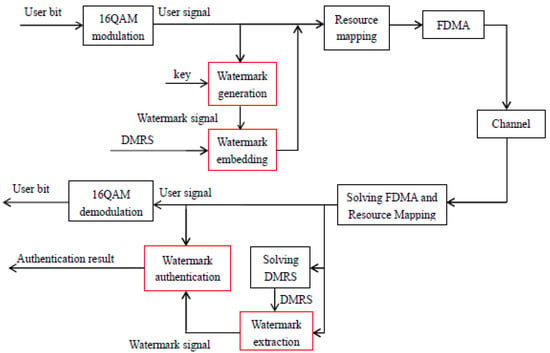
Figure 1.
Watermark system model on 5G NR. The black box represents the signal generation process specified by the existing 5G protocol, and the red box represents the embedding and extraction process of the watermarking scheme designed in this paper. In the model, FDMA means frequency division multiple access and DMRS means demodulation reference signal.
In Figure 1, the black box represents the signal generation process specified by the existing 5G protocol, and the red box represents the embedding and extraction process of the watermarking scheme designed in this paper. It is worth noting that the design of this watermarking scheme was applied to the existing 5G NR system, but to minimize the coupling with the existing system, this watermarking scheme is independent of the existing 5G protocol stack. Therefore, in the watermarking scheme, the processes of channel coding and scrambling of user bits are not involved (scrambling sequence involves higher layer configuration, which is unknown in this watermarking scheme).
In the communication system, the watermark is first generated by the sender and embedded in the transmitted signal, and then the receiver extracts the watermark from the transmitted signal. At the same time, the receiver also regenerates a watermark and compares the generated watermark with the extracted watermark to complete the authentication process.
2.1. Basic Watermarking Scheme
The basic watermarking scheme is discussed: the basic watermark generation scheme, embedding scheme, extraction, and authentication scheme are introduced. For the basic watermarking scheme, the watermark generation and embedding schemes were first proposed in [12], and we just apply these in the 5G NR here.
2.1.1. Watermark Generation Scheme
If the embedded watermark bits are the same in each data frame, the watermark can be easily obtained by other receivers. Therefore, to implement identity authentication, the basic watermark generation method is to determine a common key, then hash the key with the user bits, and take the hashed result as watermark bits [19]. The watermark generation scheme can be shown in Figure 2. An interception step is added after the hash operation to get the appropriate watermark length. The hash algorithm used in this paper is SHA-1 [20].

Figure 2.
Basic watermark generation scheme.
2.1.2. Watermark Embedding Scheme
In the uplink of 5G system, the multiple access mode is SC-FDMA. In the protocol, the base sequence of DMRS is modulated by quadrature phase shift keying (QPSK) as follows.
where n is the number of the subcarrier, determines the phase of the nth subcarrier, and its values are and . x(n) is the base sequence of DMRS, which is one of the 30 groups specified in the protocol. When embedding the watermark, the QPSK signal can be rotated clockwise or counterclockwise according to the watermark bit—that is, the watermark signal is embedded into the phase of DMRS:
where is the embedded watermark signal, a is the embedded strength, w(n) is the watermark bit embedded in the nth subcarrier, and its value is . y(n) is the base sequence of DMRS after embedding the watermark. The constellations are shown in Figure 3.
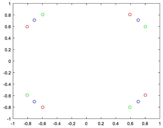
Figure 3.
The constellation of symbols. Blue circles indicate the constellation of symbols specified in the protocol, green circles indicate the constellation after embedding bit 0 of the watermark, and red circles indicate the constellation after embedding bit 1 of the watermark.
In Figure 3, blue circles indicate the symbols of DMRS specified by the protocol, which are the standard QPSK symbols. Green circles indicate the symbols after embedding the bit 0 of the watermark, and rotating them clockwise by a radian. Red circles indicate the symbols after embedding bit 1 of the watermark, and rotating them counterclockwise by a radian. The watermark bit is embedded through different rotation directions.
2.1.3. Watermark Extraction and Authentication Scheme
After embedding the watermark, for the receiver, the base sequence of DMRS can be expressed as:
where is the received base sequence of DMRS, and it is assumed that there is a phase offset after transmission through the channel. The phase offset obtained by channel estimation is [21]. Then, the phase obtained by the receiver is compared with the phase of the standard base sequence:
Then, judge the transmitted watermark bits by
The constellation of is shown in Figure 4. In Figure 4, it is assumed that DMRS occupies 24 subcarriers. Compared with the standard , there is a deviation in the calculated phase of DMRS, which is introduced by the watermark .
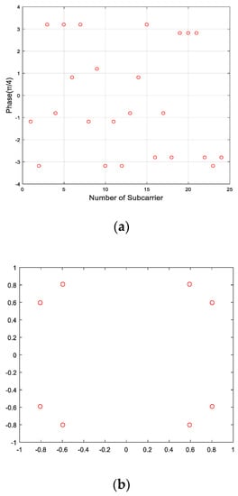
Figure 4.
Demodulated phase of DMRS. (a) Phase of DMRS. (b) Constellation of DMRS.
In addition to extracting the watermark from the transmission signal, the receiver needs to regenerate the watermark to complete the authentication. The receiver and the sender share the key, and at the same time, the receiver can demodulate the user bits , then hash the key and the user bits , and intercept the hashed result to an appropriate length to regenerate the watermark bit . Finally, according to whether the watermark bit generated by the receiver, , is the same as the watermark bit extracted by the receiver, , it is determined whether the authentication is successful:
where represents the final authentication result and G is the threshold. represents authentication success, and represents authentication failure. The watermark authentication scheme is shown in Figure 5.

Figure 5.
Basic watermark authentication scheme.
To briefly summarize the above process, the sender first generates a watermark, embeds the watermark into the phase of the base sequence of DMRS in 5G NR system, and then transmits the watermark-embedded signal. The receiver first receives the signal, demodulates the received signal, and extracts the watermark embedded by the sender. Then, the receiver regenerates the watermark signal according to the demodulated user’s signal, and completes the authentication process by comparing the extracted watermark with the regenerated watermark.
2.2. Improved Watermarking Scheme
Although the basic watermarking scheme can be directly applied to 5G NR system, the watermark reduces the reliability of user-data transmission, since the watermark modifies the normal DMRS. The improved watermarking scheme is proposed according to the characteristics of 5G NR system, where the robustness of the watermark is improved and the effect of the watermark on the user-data transmission is negligible.
2.2.1. Improved Watermark Generation Scheme
The basic watermark generation scheme has the prerequisite for successful authentication: that the demodulated user symbols and watermark bits are both completely right. For the receiver, in addition to extracting the watermark bits embedded by the sender from the received signal, the receiver’s key should be hashed with the user bits demodulated by the receiver to regenerate the watermark. If the watermark generated by the receiver is the same as the extracted watermark, the authentication is successful. Otherwise, the authentication fails. Therefore, when one of the demodulated user symbols is wrong, even if the sender’s watermark is correctly transmitted to the receiver, the receiver cannot generate a consistent watermark, resulting in authentication failure.
When there are errors in user data, even if there is only one symbol error, the hashed results will be completely inconsistent, which directly leads to the failure of identity authentication. Therefore, the premise that authentication is successful only when demodulation is completely correct is not very reasonable in practical applications. How to correctly design a watermark generation scheme which can implement different watermarks for different data frames without depending on the correct demodulation of the user’s signal is an important aspect of improving watermark generation schemes. How to reduce the bit error rate of watermark bits during transmission is another aspect of improving watermark generation schemes.
To solve the above problems, in this paper, channel coding is added to the watermark generation scheme, and the receiver can increase the accuracy of watermark extraction through channel decoding. In this paper, (7, 4) cyclic code is used as the channel coding method of the watermark signal [22]. In addition, when the modulation scheme adopted by the user’s signal is 16QAM, there are three different amplitudes, so the user bits can be replaced by the modulus of the user’s symbol as the input of hash encryption, as shown in Figure 6. In Figure 6, blue represents the user bits as the input of the hash, and red circles represent the moduli of the user symbols as the input of hash encryption.
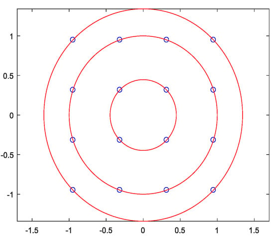
Figure 6.
Two input forms of hash encryption. Blue circles represent the user symbols as the input of hash (each points represents four user bits), and red circles represent the modulus of user symbols as the input of hash encryption.
When the user bits are used as the input of hash encryption, it must be ensured that every point on the constellation can be correctly judged. When the modulus of the user’s signal is used as the input of hash, one only needs to ensure that the judged modulus is equal to the real modulus. Obviously, by using the modulus of the user’s signal instead of the user bits as the input of the hash algorithm, the authentication error caused by the transmission error of user bits can be reduced. It is worth noting that the three moduli in 16QAM are not uniformly distributed. In Figure 6, the three moduli are 0.4472, 1, and 1.3416 in turn, which are denoted as , and , and their differences are 0.5528 and 0.3416. It can be seen that the difference between the larger two moduli is small, which may confuse one when judging the modulus. The ultimate goal of the watermark generation scheme is to generate different watermarks for different data frames, so it does not emphasize the accurate judgment of modulus, and only needs the changing of the modulus in different data frames. To improve the accuracy of the judging modulus, two larger moduli can be regarded as the same situation and then distinguished from the smallest modulus. In this paper, the distinguishing modulus is defined as the pseudo-user-bit, and the formula is as follows:
The user’s signal after 16QAM modulation is marked as s, is the value of the smallest modulus, is the value of the second smallest modulus, and the mapping result is called a pseudo-user-bit, which is denoted as .
The improved watermark generation scheme is shown in Figure 7. In Figure 7, Scheme I is the basic watermark generation scheme, which is described in Section 2.1; for comparison, it is still displayed here. Scheme II adds channel coding on this basis, and Scheme III is further improved, using a pseudo-user-bit instead of a user bit as the input of the hash algorithm. To distinguish them, in this paper, the watermark bits before encoding are called watermark source bits and are denoted as , and the watermark bits embedded in DMRS after encoding are called watermark embedded bits and are denoted as w. b stands for user bits, and after modulation, the user’s signal s is obtained, and then it is mapped to obtain the pseudo-user-bit, which is recorded as . The key is the shared key between legal communication parties. For the above three schemes, a unique watermark signal can be generated for each different data frame.
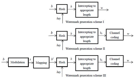
Figure 7.
Watermark generation schemes. Scheme I is the basic watermark generation scheme, Scheme II adds channel coding on this basis, and Scheme III uses the pseudo-user-bit instead of the user symbol as the input of the hash algorithm.
2.2.2. Improved Watermark Embedding Scheme
In Section 2.1, the process of embedding the watermark signal into the phase of the DMRS was described in detail. However, the DMRS is of great significance and is the basis for demodulating the user’s signal. An important principle of embedding watermark information into the DMRS is to minimize the influence of the watermark on channel estimation and then reduce the interference with users’ signals.
For the receiver, after embedding the watermark, the DMRS is expressed in (3). To calculate this phase offset, the signal can be quadrupled first, and the result is as follows:
When using DMRS to estimate the channel, the phase can be calculated as follows:
where n is the number of subcarriers. To accurately calculate the phase offset caused by signal transmission in the channel, the embedded watermark bits must meet the following conditions:
Since , (11) can be equal to
We call this important condition the symmetry of the watermark. In this paper, to realize the symmetry of the watermark, the channel coding in the watermark generation scheme is improved. Firstly, every four watermark bits are divided into a group, and each group of watermark bits is coded by (7, 4), a cyclic code. Finally, according to the value of bit 1 in the 7-bit code, bit 0 or bit 1 is duplicated in the 8th bit to realize the symmetry of the watermark. It is worth noting that there are all 0s and all 1s in the traditional cyclic coding, at which time the symmetry of the watermark cannot be realized. Therefore, the information codes with all 0s and 1s can be regarded as adjacent information codes 0001 and 1110, and then encoded. The mapping relationship of the improved (7, 4) cyclic codes is summarized in Table 1. The number of watermark bits after coding is twice that before coding. There are two DMRS symbols in each sub-frame, and each symbol occupies 24 subcarriers. If channel coding is not performed, the number of watermark source bits that can be transmitted in each sub-frame is 48, and if channel coding is performed, the number of watermark source bits in each sub-frame is 24.

Table 1.
Improved (7, 4) cyclic codes.
2.2.3. Improved Watermark Embedding Scheme
The watermark authentication schemes corresponding to three different watermark generation schemes are shown in Figure 8. In Figure 8, Scheme I is the existing watermark authentication scheme, in which the demodulated user bits and the key are hashed together to regenerate the watermark , and then the generated watermark is compared with the directly extracted watermark to complete the authentication process. Scheme II is an improved version of Scheme I. The extracted watermark is decoded to obtain watermark source bits and then compared with the regenerated watermark source bits to complete authentication, which can reduce authentication errors caused by transmission errors of the watermark. Scheme III is further improved by using pseudo-user-bits instead of user bits to generate watermarks, thereby reducing authentication errors caused by demodulation errors of user’s signals.
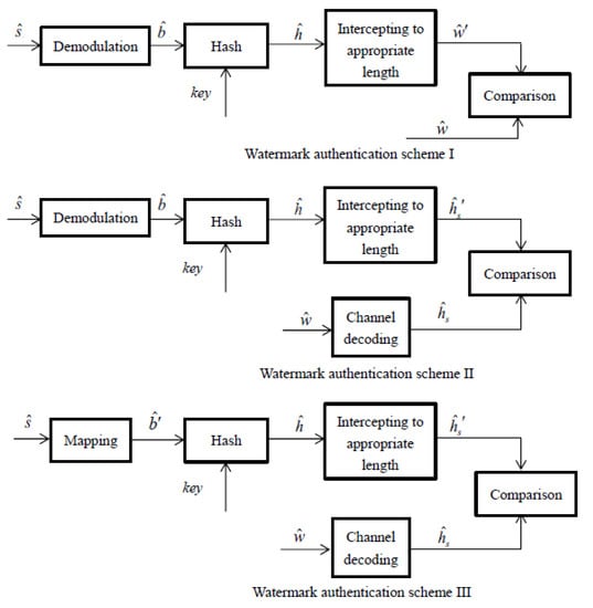
Figure 8.
Watermark authentication schemes for scheme I, scheme II and scheme III.
It should be noted that when channel coding is carried out, every 4-bit watermark source is coded into a 7-bit channel code, and then the 8th bit is supplemented according to the number of bit 1 in the 7-bit code to realize the symmetry of the watermark. Meanwhile, all 0 s and all 1 s are regarded as 0001 and 1110 before coding. Therefore, correspondingly, at the receiving end, 8 bits are taken as a group, and the first 7 bits are decoded to extract the watermark source bits. At the same time, among the watermark source bits regenerated by the receiver, all 0 s and all 1 s should be regarded as 0001 and 1110, and then compared with the extracted watermark source bits to complete the authentication process.
2.3. Performance Analysis for Bit Error Rate
In this section, the bit error rate of the proposed watermarking scheme in the Gaussian channel and in the Rayleigh fading channel is analyzed theoretically. In the watermarking scheme proposed in this paper, the modulation mode of the user’s signal is 16QAM, the base sequence of DMRS is QPSK signal, and the watermark is embedded in the base sequence of DMRS by phase rotation. This section mainly analyzes the symbol error rate of users’ signals and the bit error rate of watermark embedded bits under ideal conditions, that is, assuming that synchronization is completely accurate and the channel estimation by DMRS is also completely accurate. In actual communication, the signal will be attenuated. To make the system more suitable for practical applications, in this paper, DMRS is used for channel estimation in both the Gaussian channel and the Rayleigh fading channel. In the Gaussian channel, the fading coefficient should be constant.
2.3.1. Symbol Error Rate of the User’s Symbol
For the Gaussian channel, the fading coefficient of the signal is constant; for the Rayleigh fading channel, in the case of slow fading [23], it can be considered that the fading coefficient in one symbol period is also approximately constant, and the attenuation coefficient is marked as μ.
Under ideal conditions, although the watermark signal is embedded into the phase of DMRS, due to the symmetry of the watermark, it will not affect the channel estimation of DMRS, so it will not affect the symbol error rate of the user’s signal. In theory, the symbol error rate of the user’s signal should be the same as the symbol error rate of standard 16QAM.
The theoretical symbol error rate of 16QAM can be calculated as:
where , μ is the attenuation coefficient, Es is the average symbol energy, and n0 is the power spectral density of noise. For the Gaussian channel, η is the constant 1, so the symbol error rate of the user’s signal in the Gaussian channel can be expressed as
For Rayleigh fading channels, η obeys the distribution:
Therefore, in fading channel, the average symbol error rate can be calculated as:
2.3.2. Bit Error Rate of the Watermark Bit
In this paper, the watermark is embedded into the phase of DMRS, and the DMRS is a QPSK signal. According to the reference [24], when the watermark is embedded into the QPSK signal in the way of phase rotation, the bit error rate of the watermark can be expressed as:
where , μ is the attenuation coefficient, Es is the average symbol energy, n0 is the power spectral density of noise, and θ is the radian of phase rotation. For the Gaussian channel, η is the constant 1, so the bit error rate of the watermark bit in the Gaussian channel can be expressed as:
Substituting (18) to (16), we obtain the average bit error rate of the watermark bit.
3. System Performance Simulation
After designing the watermarking scheme, it is necessary to estimate the performance of the watermarking scheme. In this paper, the original system parameters are designed as follows: the sampling rate is 30.72 M, the subcarrier spacing is 15 kHz, the system occupies 24 subcarriers, the modulation format of user’s signal is 16QAM, and the modulation format of DMRS is QPSK. In the design of the watermark system, the key is unified as “keyforphone1,” the hash algorithm is SHA-1, and the watermark embedding strength is 0.2. Under each channel condition, 10,000 data frames are sent and received. In this section, we consider two channel environments: Gaussian channel and fading channel. In each channel, we discuss two cases: ideal carrier synchronization and synchronization with carrier frequency offset to evaluate the performance comprehensively.
3.1. System Performance in the Gaussian Channel
Three watermarking schemes are investigated in the paper. The first one is to hash the user bits with the key, and the intercepted watermark source bits are directly embedded into the phase of DMRS, which is the basic watermarking scheme and comes from the idea proposed in [12]. The second one is to encode the watermark source bits and then embed them into the phase of DMRS after satisfying the symmetry of the watermark. The third one is further improved, in which the pseudo-user-bits replace the user bits as the input of the hash algorithm. The above three watermarking schemes are referred to as Watermarking Scheme I, Watermarking Scheme II, and Watermarking Scheme III in turn. System performance evaluation indexes include the symbol error rate of user data, the bit error rate of watermark bits, the transmission success rate of user data, the transmission success rate of watermark bits, and the authentication success rate of watermark bits. The success rate of watermark authentication is related to two indicators, the transmission success rate of user data (the ratio of data frames in which the user data are transmitted correctly) and the transmission success rate of watermark bits, so the success rate of watermark authentication is judged by these two indicators.
3.1.1. System Performance under Ideal Carrier Synchronization
Firstly, it is assumed that the carrier frequency of the transmitter is completely synchronized with the carrier frequency of the receiver. In the Gaussian channel, the performances of three watermarking schemes are compared. The symbol error rates of user data in three watermark schemes are shown in Figure 9.
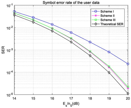
Figure 9.
Symbol error rates of the user data under ideal synchronization in the Gaussian channel.
In Figure 9, the symbol error rates of user signals in Scheme II and Scheme III are consistent, and both are similar to the theoretical symbol error rate of 16QAM, lower than that in Scheme I. This is because the watermark signals in Scheme II and Scheme III meet the requirement of symmetry, so when using DMRS to estimate the channel, the results in Scheme II and Scheme III are more accurate and cause less interference with the user signals, so the symbol error rates of user signals are lower. The difference between Scheme II and Scheme III is that the input of hash operation is different, so it has little effect on the user’s signal, and there is no difference in the symbol error rate of the user’s signal between the two schemes. In Figure 9, compared with the theoretical symbol error rate of 16QAM, there is still a gap in the user’s signal error rates in Scheme II and Scheme III, because channel estimation of the DMRS is not completely accurate.
Figure 10 shows the transmission bit error rate of watermark bits. In Figure 10, the bit error rate of the watermark bits in Scheme I is higher than those of Scheme II and Scheme III. This is because channel coding can be used for error detection and correction at the receiving end. It can be seen that the performance of the watermark in the transmission process is improved by using channel coding, which can not only avoid interference to channel estimation but also correct errors at the receiver.
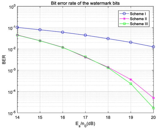
Figure 10.
Bit error rate of the watermark bits under ideal synchronization in the Gaussian channel.
The success rates of user-data transmission and the success rates of watermark authentication in three watermarking schemes are compared in Figure 11. In Figure 11, the success rates of user-data transmission in Scheme II and Scheme III are the same and higher than that in Scheme I, which is due to the symmetry of watermarks in Scheme II and Scheme III. The success rate of watermark authentication in Scheme I is far lower than that of user-data transmission. As the channel coding process is absent in Scheme I, the receiver cannot correct the watermark. Even if the user data are successfully transmitted, the authentication may fail because of the error of watermark-bit transmission. The success rate of watermark authentication in Scheme II is very close to the success rate of user-data transmission because channel coding is added in Scheme II, so the transmission accuracy of the watermark is greatly improved compared with Scheme I. In Scheme III, the success rate of watermark authentication is consistent with the success rate of user-data transmission. Even when the signal-to-noise ratio is low, the authentication rate is higher than the success rate of user-data transmission, because pseudo-user-bits are used instead of user bits as the input of the hash algorithm in Scheme III. Even if some user’s signals are demodulated incorrectly, as long as the mapped pseudo-user-bits are correct, the same watermark source bits can still be generated to complete watermark authentication. Therefore, when the success rates of user-data transmission in Scheme II and Scheme III are the same, the authentication success rate in Scheme III is sometimes higher than that in Scheme II.
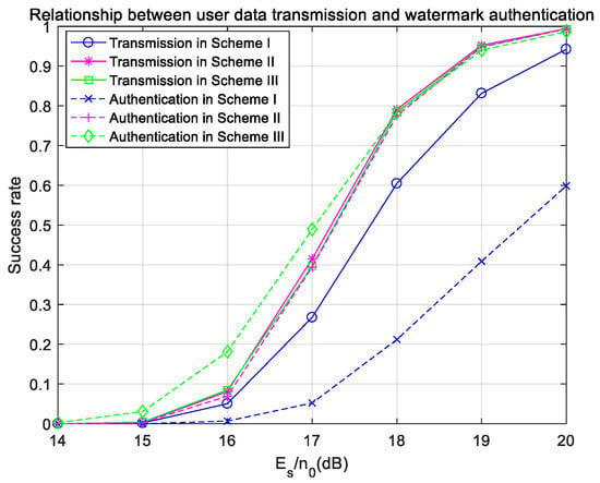
Figure 11.
Success rates of user data transmission and watermark authentication under ideal synchronization in the Gaussian channel.
The success rates of watermark-bit transmission and watermark authentication in the three schemes are compared, and the results are shown in Figure 12. In Figure 12, the success rates of watermark bits and watermark authentication in Scheme I are lower than those in Scheme II and Scheme III, which directly illustrates the importance of watermark coding. Scheme II and Scheme III have the same success rate of watermark transmission, but when the signal-to-noise ratio is low, the success rate of watermark authentication in Scheme III is slightly higher than that in Scheme II, which shows that using pseudo-user-bits as the input of hash operation can further improve the success rate of watermark authentication.
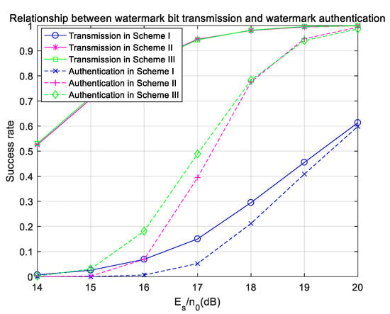
Figure 12.
Success rates of watermark-bit transmission and watermark authentication under ideal synchronization in the Gaussian channel.
3.1.2. System Performance with Carrier Frequency Offset
In the previous section, the system’s performance under ideal carrier synchronization was analyzed. However, in practical applications, it is very difficult to achieve this condition. When the frequency stability of a mobile phone is 0.1 ppm and the carrier frequency is 2.6 GHz, the possible carrier frequency offset is 260 Hz, and the 5G NR system is sensitive to frequency offsets. Therefore, this section takes the frequency offset of 90 Hz as an example to analyze the performance of the watermarking system.
When the frequency offset is 90 Hz, the symbol error rate of the user’s signal is shown in Figure 13. The symbol error rates of user data in Scheme II and Scheme III are still very close, and lower than that in Scheme I, which is also due to the symmetry of the watermark. However, the symbol error rates in the three schemes are much higher than the theoretical symbol error rate of 16QAM, which reflects the sensitivity of the 5G NR system to frequency offsets. When the frequency estimation is incorrect, the symbol error rate of the user data will increase significantly.
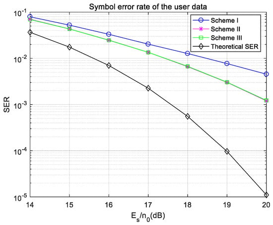
Figure 13.
Symbol error rate of user data with a frequency offset in the Gaussian channel.
The transmission bit error rates of watermark bits are plotted, and the results are shown in Figure 14. Figure 14 shows the bit error rates of watermark source bits in three schemes with a frequency offset, and also shows the bit error rate of watermark source bits in Scheme III with ideal carrier synchronization. Simulation results show that the bit error rates of watermark source bits in Scheme II and Scheme III can keep the same level as the ideal synchronization, and are far lower than that in Scheme I, since the bit error rate of watermark bits is significantly reduced by channel coding.
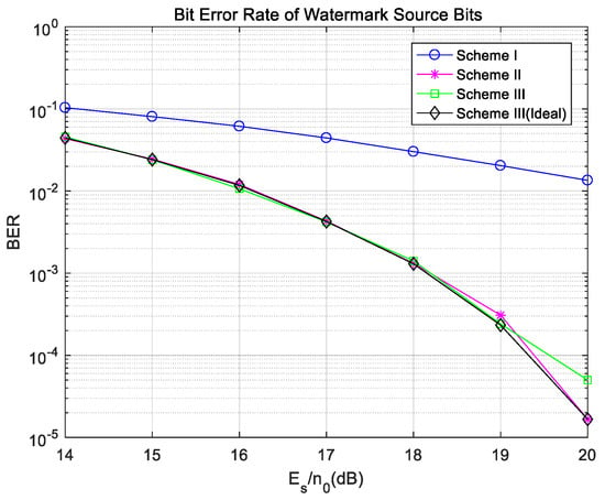
Figure 14.
Bit error rate of the watermark bits with a frequency offset in the Gaussian channel.
Figure 15 shows the success rates of user-data transmission and watermark authentication in three schemes with a frequency offset, and also gives the success rate of user-data transmission and watermark authentication in Scheme III under ideal synchronization for comparison. In Figure 15, the success rate of watermark authentication in Scheme I is lower than that of user-data transmission, because the watermark signal in Scheme I is not encoded, so the bit error rate of the watermark signal is high, which affects the success rate of watermark authentication. The success rates of user data in Scheme II and Scheme III are very similar, and both are lower than that in ideal synchronization, because the 5G NR system is very sensitive to frequency offsets. However, it is worth noting that the success rate of watermark authentication in Scheme III is higher than that in Scheme II, which can be similar to the success rate of watermark authentication under ideal synchronization. This is because in Scheme III pseudo-user-bits are used instead of user bits as the input for the hash operation. When the received signal has a frequency offset, the error rate of user data will increase significantly, but its modulus will not change. Therefore, when pseudo-user-bits are used as the input of hash operation, even if the user symbols are determined incorrectly, the pseudo-user-bits mapped by user’s signals are still correct, and authentication can still be completed. Figure 15 can clearly show the advantages of Scheme III. When there is a frequency offset, the success rate of watermark authentication is kept at the same level as that under ideal synchronization, which means Scheme III has good anti-frequency-offset performance.
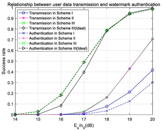
Figure 15.
Success rates of user-data transmission and watermark authentication with a frequency offset in the Gaussian channel.
Finally, the comparison of the success rates of watermark bits and watermark authentication is shown in Figure 16. The transmission and authentication success rates of watermark bits in Scheme III under ideal carrier synchronization are also shown for comparison. In Figure 16, the success rates of watermark-bit transmission in Scheme II and Scheme III are higher than that in Scheme I and reach the same level as the ideal situation, which is due to the watermark coding and the symmetry of the watermark. When there is a frequency offset, the success rate of watermark authentication Scheme III can reach the same level as the ideal synchronization. However, in Scheme II, because the success rate of user-data transmission drops significantly, even if the success rate of watermark transmission can reach the level of ideal synchronization, the authentication success rate is lower than that under ideal synchronization.
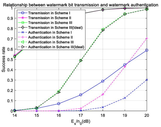
Figure 16.
Success rates of watermark-bit transmission and watermark authentication with a frequency offset in the Gaussian channel.
According to the above simulation results, in Scheme III, by coding the watermark bits, the bit error rate of watermark bits can be significantly reduced. By satisfying the symmetry of the watermark, the interference with user data can be reduced and the symbol error rate of user data can be reduced. By using pseudo-user-bits instead of user bits as the input of the hash operation, the success rate of watermark authentication can be guaranteed to reach the same level as the ideal synchronization when the received signal has no frequency offset. Therefore, Watermarking Scheme III has good anti-noise and anti-frequency-offset performance, and suppresses interference with the user data.
3.2. System Performance in the Fading Channel
In the fading channel, the strength of the signal changes at the receiver. In some cases, signal fading is more serious, so it is difficult to complete identity authentication. Therefore, in the fading channel, the result of channel estimation using DMRS is investigated, and a threshold is set. If the modulus of channel response is lower than the threshold, the channel is considered to be fading seriously, and identity authentication is abandoned. In this paper, the threshold is set to 0.7.
3.2.1. System Performance under Ideal Carrier Synchronization
In Figure 17, the symbol error rates of user’s signal in Scheme II and Scheme III are consistent, and both are similar to the theoretical symbol error rate of 16QAM and lower than that in Scheme I. Compared with the theoretical symbol error rate of 16QAM, there is still a gap between the user’s signal error rates in Scheme II and Scheme III, because channel estimation of the DMRS is not completely accurate.
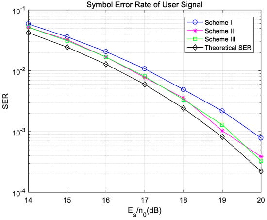
Figure 17.
Symbol error rate of the user data under ideal synchronization in the fading channel.
A comparison of the success rate of user-data transmission and watermark authentication in three schemes is shown in Figure 18. The success rate of watermark authentication in Scheme I is far lower than that of user-data transmission, but they are very similar in Scheme II and Scheme III, which proves the importance of channel coding. The success rate of user-data transmission in Scheme II is the same as that in Scheme III, but the authentication success rate in Scheme III is slightly higher than that in Scheme II, which is because pseudo-user-bits are used to generate watermarks in Scheme III.
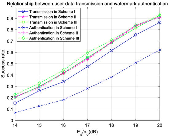
Figure 18.
Success rates of user-data transmission and watermark authentication under ideal synchronization in the fading channel.
Finally, the success rate of watermark-bit transmission and the success rate of watermark authentication are compared in Figure 19. The transmission success rate in Scheme I is much lower than those in Scheme II and Scheme III, and the authentication success rate in Scheme I is limited by the transmission success rate, because Scheme I does not carry out channel coding on the watermark bits. Scheme II and Scheme III have the same success rate of watermark transmission, but the authentication success rate in Scheme III is slightly higher than that in Scheme II, because Scheme III uses pseudo-user-bits instead of user bits as parameters to generate watermarks. The authentication success rate in Scheme II and Scheme III is limited by the success rate of user-data transmission.
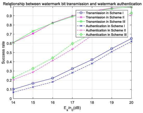
Figure 19.
Success rates of watermark-bit transmission and watermark authentication under ideal synchronization in the fading channel.
3.2.2. System Performance in the Presence of Carrier Frequency Offset
In an actual system, it is difficult to achieve accurate synchronization of the carrier frequency. Similarly to the Gaussian channel, this section analyzes the system’s performance when the carrier frequency offset is 90 Hz. The authentication threshold is set to 0.7, as in the case of ideal carrier synchronization.
The success rates of user-data transmission and watermark authentication are shown in Figure 20. The success rates of user-data transmission and watermark authentication in Scheme III under ideal synchronization are also given. The success rate of watermark authentication in Scheme I is lower than that of user-data transmission because the watermark in Scheme I is not encoded. The success rate of watermark authentication in Scheme II is almost the same as the success rate of user-data transmission, because the watermark is encoded in Scheme II, and the success rate of watermark authentication depends on the success rate of user-data transmission. The success rate of watermark authentication in Scheme III is much higher than the success rate of user-data transmission because pseudo-user-bits are used instead of user bits as the input of hash operation in Scheme III. Even if the user’s signal makes a wrong decision due to frequency offset, the mapped pseudo-user-bits may still be correct, thus ensuring the accuracy of watermark authentication. Therefore, in the presence of frequency offset, the success rates of user’s signal transmission in Scheme II and Scheme III are the same, far lower than that in ideal synchronization, but the success rate of watermark authentication in Scheme III can be consistent with that in ideal synchronization, far higher than that in Scheme II. Figure 19 directly shows the anti-noise and anti-frequency-offset effects of Scheme III in the fading channel.
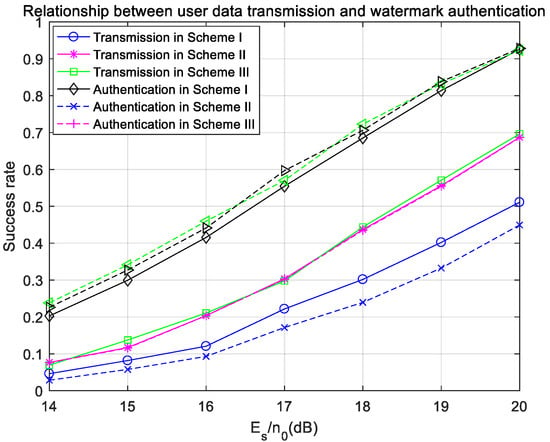
Figure 20.
Success rates of user-data transmission and watermark authentication with frequency offset in the fading channel.
Finally, the success rates of watermark-bit transmission and watermark authentication in three schemes are compared in Figure 21. Under the condition of frequency offset, the transmission success rates of watermark bits in Scheme II and Scheme III can reach the transmission success rate of watermark bits in ideal synchronization, and are much higher than that in Scheme I. However, because the symbol error rate of user data is increased due to the existence of the frequency offset, the receiver in Scheme II may not be able to generate the same watermark as the sender, so the authentication success rate in Scheme II is lower than that in Scheme III. Figure 20 intuitively shows that when a frequency offset exists, the transmission success rate and authentication success rate of watermark source bits in Scheme III can reach the same level as in the case of ideal synchronization; that is, Watermark Scheme III has good anti-frequency-offset performance.
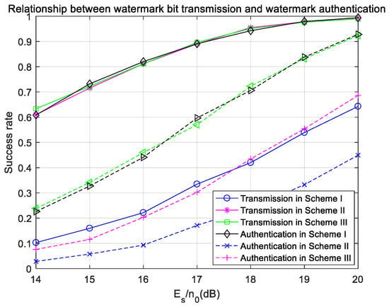
Figure 21.
Success rates of watermark-bit transmission and watermark authentication with frequency offset in the fading channel.
According to the above simulation results, Watermarking Scheme III, which was proposed in this paper, is also feasible for fading channels and has good anti-noise and anti-frequency-offset performance.
4. Conclusions
Based on the existing 5G physical-layer protocol, we designed a suitable watermarking scheme which can be used to transmit identity authentication information and enhance the physical-layer security in communication. The watermarking scheme proposed in this paper introduces channel coding into the watermark generation scheme, which can improve the success rate of watermark transmission. At the same time, the watermark signal is embedded into the demodulation reference signal, which avoids the interference of the watermark signal with the user’s signal as much as possible by satisfying the symmetry of the watermark. Finally, the watermark is generated by the pseudo-user-bits instead of the user bits, which improves the success rate of watermark authentication. In this paper, the performance of the proposed watermarking scheme was tested in the Gaussian channel and fading channel. Generally speaking, the watermarking scheme proposed in this paper has good anti-noise and anti-frequency-offset performance and has good feasibility for both channels.
Author Contributions
Conceptualization, X.X.; methodology, X.X. and Z.X.; investigation, W.C.; writing—original draft preparation, W.C.; writing—review and editing, Z.X.; project administration, Z.X. All authors have read and agreed to the published version of the manuscript.
Funding
This research received no external funding.
Conflicts of Interest
The authors declare no conflict of interest.
References
- Mathur, S.; Reznik, A.; Ye, C.; Mukherjee, R.; Rahman, A.; Shah, Y.; Trappe, W.; Mandayam, N. Exploiting the physical layer for enhanced security. IEEE Wirel. Commun. 2010, 17, 63–70. [Google Scholar] [CrossRef]
- Shin, M.; Ma, J.; Mishra, A.; Arbaugh, W.A. Wireless network security and interworking. Proc. IEEE 2006, 94, 455–466. [Google Scholar] [CrossRef]
- Potlapally, N.R.; Ravi, S.; Raghunathan, A.; Jha, N.K. A study of the energy consumption characteristics of cryptographic algorithms and security protocols. IEEE Trans. Mob. Comput. 2006, 5, 128–143. [Google Scholar] [CrossRef]
- Brik, V.; Banerjee, S.; Gruteser, M.; Oh, S. Wireless device identification with radiometric signatures. In Proceedings of the 14th ACM International Conference on Mobile Computing and Networking, Francisco, CA, USA, 14–19 September 2008; pp. 116–127. [Google Scholar]
- Wu, X.; Yang, Z. Physical-Layer Authentication for Multi-Carrier Transmission. IEEE Commun. Lett. 2015, 19, 74–77. [Google Scholar] [CrossRef]
- Yu, P.L.; Verma, G.; Sadler, B.M. Wireless physical layer authentication via fingerprint embedding. IEEE Commun. Mag. 2015, 53, 48–53. [Google Scholar] [CrossRef]
- Yu, P.L.; Baras, J.S.; Sadler, B.M. Physical-Layer Authentication. IEEE Trans. Inf. Forensics Secur. 2008, 3, 38–51. [Google Scholar] [CrossRef]
- Yu, P.L.; Baras, J.S.; Sadler, B.M. Multicarrier authentication at the physical layer. In Proceedings of the International Symposium on a World of Wireless, Mobile and Multimedia Networks, Newport Beach, CA, USA, 23–26 June 2008; pp. 1–6. [Google Scholar]
- Yu, P.L.; Sadler, B.M. MIMO Authentication via Deliberate Fingerprinting at the Physical Layer. IEEE Trans. Inf. Forensics Secur. 2011, 6, 606–615. [Google Scholar] [CrossRef]
- Tan, X.; Borle, K.; Du, W.; Chen, B. Cryptographic link signatures for spectrum usage authentication in cognitive radio. In Proceedings of the ACM Conference on Wireless Network Security, Hamburg, Germany, 14–17 June 2011; pp. 79–90. [Google Scholar]
- Jiang, T.; Zeng, H.; Yan, Q.; Lou, W.; Hou, Y.T. On the limitation of embedding cryptographic signature for primary transmitter authentication. IEEE Wirel. Commun. Lett. 2012, 1, 324–327. [Google Scholar] [CrossRef]
- Verma, G.; Yu, P.; Sadler, B.M. Physical layer authentication via fingerprint embedding using software-defined radios. IEEE Access 2015, 3, 81–88. [Google Scholar] [CrossRef]
- Zhang, P.; Liu, J.; Shen, Y.; Li, H.; Jiang, X. Lightweight tag-based PHY-layer authentication for IoT devices in smart cities. IEEE Internet Things J. 2020, 7, 3977–3990. [Google Scholar] [CrossRef]
- Ran, Y.; Al-Shwaily, H.; Tang, C.; Tian, G.Y.; Johnston, M. Physical layer authentication scheme with channel based tag padding sequence. IET Commun. 2019, 13, 1776–1780. [Google Scholar] [CrossRef]
- Xie, N.; Chen, Y. Pilot-Based Physical-Layer Authentication with High Covertness. IEEE Wirel. Commun. 2020, 28, 97–103. [Google Scholar] [CrossRef]
- Xie, N.; Li, Z.; Tan, H. A Survey of Physical-Layer Authentication in Wireless Communications. IEEE Commun. Surv. Tutor. 2021, 23, 282–310. [Google Scholar] [CrossRef]
- 3GPP TS 36.211 v11.0.0; LTE Physical Channels and Modulation. European Telecommunications Standards Institute: Sophia Antipolis, France, 2012.
- 3GPP TS 38.211 v16.3.0; NR Physical Channels and Modulation. European Telecommunications Standards Institute: Sophia Antipolis, France, 2020.
- Meneze, A.J.; Oorschot, P.C.; Vanstone, S.A. Handbook of Applied Cryptography; CRC Press: Boca Raton, FL, USA, 2001. [Google Scholar]
- Dang, Q.H. The Keyed-Hash Message Authentication Code (HMAC): FIPS Pub 1981; National Institute of Standards and Technology: Gaithersburg, MD, USA, 2008. [Google Scholar]
- Hou, X.; Zhang, Z.; Kayama, H. DMRS Design and Channel Estimation for LTE-Advanced MIMO Uplink. In Proceedings of the 70th IEEE Vehicular Technology Conference Fall, Anchorage, AK, USA, 20–23 September 2009; pp. 20–23. [Google Scholar]
- Prange, E. The use of information sets in decoding cyclic codes. IRE Trans. Inf. Theory 1962, 8, 5–9. [Google Scholar] [CrossRef]
- Nylund, H.W. Characteristics of small-area signal fading on mobile circuits in the 150 MHz band. IEEE Trans. Veh. Technol. 1968, 17, 24–30. [Google Scholar] [CrossRef]
- Xu, Z.; Yuan, W. Watermark BER and Channel Capacity Analysis for QPSK-Based RF Watermarking by Constellation Dithering in AWGN Channel. IEEE Signal Process. Lett. 2017, 24, 1068–1072. [Google Scholar] [CrossRef]
Publisher’s Note: MDPI stays neutral with regard to jurisdictional claims in published maps and institutional affiliations. |
© 2022 by the authors. Licensee MDPI, Basel, Switzerland. This article is an open access article distributed under the terms and conditions of the Creative Commons Attribution (CC BY) license (https://creativecommons.org/licenses/by/4.0/).