Article

An Autonomous Vehicle Stability Control Using Active Fault-Tolerant Control Based on a Fuzzy Neural Network

1
Department of Electrical Engineering, College of Engineering, Najran University, Najran 11001, Saudi Arabia
2
Department of Electrical Engineering, FAST National University of Computer and Emerging Sciences, Chiniot Faisalabad Campus, Chiniot 35400, Punjab, Pakistan
*
Author to whom correspondence should be addressed.
Electronics 2022, 11(19), 3165; https://doi.org/10.3390/electronics11193165
Submission received: 9 September 2022 / Revised: 27 September 2022 / Accepted: 29 September 2022 / Published: 1 October 2022
(This article belongs to the Special Issue AI-Based Autonomous Driving System)

Abstract

:
Due to instability issues in autonomous vehicles, the risk of danger is increasing rapidly. These problems arise due to unwanted faults in the sensor or the actuator, which decrease vehicle efficiency. In this modern era of autonomous vehicles, the risk factor is also increased as the vehicles have become automatic, so there is a need for a fault-tolerant control system (FTCS) to avoid accidents and reduce the risk factors. This paper presents an active fault-tolerant control (AFTC) for autonomous vehicles with a fuzzy neural network that can autonomously identify any wheel speed problem to avoid instability issues in an autonomous vehicle. MATLAB/Simulink environment was used for simulation experiments and the results demonstrate the stable operation of the wheel speed sensors to avoid accidents in the event of faults in the sensor or actuator if the vehicle becomes unstable. The simulation results establish that the AFTC-based autonomous vehicle using a fuzzy neural network is a highly reliable solution to keep cars stable and avoid accidents. Active FTC and vehicle stability make the system more efficient and reliable, decreasing the chance of instability to a minimal point.

1. Introduction

To reduce pollutants and fuel consumption, the autonomous vehicle is seen as a promising vehicle architecture. It drives the four wheels with four in-wheel (or hub) motors, and each wheel’s torque and driving/braking can be adjusted independently. A system such as this eliminates actuator redundancy and allows for better vehicle allocation. However, owing to its system complexity and a large number of actuators, it has a higher failure rate than a manual car architecture, which will almost certainly result in a devastating traffic collision if one or more motors fail [1]. Improving and enhancing the reliability of the system fault-tolerance becomes dynamic research in this modern era. Fault recoverability is a major issue in fault-tolerance design. It should be noted that, in both an authentic and physical sense, system performance is highly dependent on fault harshness, which can impact system health [2].
It is important to take measures because in recent years the high number of road accidents, the unbearable road congestion, and risks of all types of pollution have increased. Inexperienced drivers and human factors can increase fuel utilization and road accident and recent research has shown these facts. Autonomous vehicles are equipped nowadays with automatic systems to ensure safety and efficiency, such as electronic stability programs, the anti-lock braking system [3], wheel speed control for stabilization [4], and collision avoidance systems [5].
In the field of autonomous driving, the research is extremely motivated. The development of autonomous driving is increasingly feasible based on the recent advances in data fusion and mechatronics. In recent years many techniques have been implemented to overcome the fault issues that arise but most of the research was done using passive fault-tolerant techniques. These were only capable of removing the fault that can occur but were not able to overcome the issues that can arise instantly due to which the autonomous vehicle system collapse and accidents occur. This paper proposes a system of active fault tolerance based on a fuzzy neural network algorithm that covers the car’s stability and allows the electric car to keep on moving even if a fault arises in run time with the help of the fuzzy neural network technique. The fuzzy and neural network techniques are combined in the proposed research to provide more efficient results and overcome noise and all random issues that can occur. The motivation of this research was to introduce an efficient and more reliable fault-tolerant technique that reduces power loss and overcomes instability issues that arise due to sensor breakdown and can cause an accident. It provides us with an efficient and reliable technique that will help the modern era to minimize the risk while traveling in an EV vehicle. This research will help to implement a reliable and more accurate technique now in the upcoming autonomous vehicles, which will guarantee safety along with minimal risk chances.
The system was trained with more than 500 data set values that were embedded in the virtual sensor for better performance. This model was implemented with the help of MATLAB/Simulink. A model was designed for the electric vehicle along with the engine attached to the tires to check the stability of the car. The optical wheel speed sensors along with the virtual sensors were attached with the help of a fuzzy neural network and PID control algorithm to check and control the tire’s speed for its accurate and efficient movement. The slip of each tire was measured so that if any error in the slip of the tires at any moment, then the brakes are applied so that the car slows down and risk can be avoided. Similarly, on each tire two sensors were attached so that if any of the sensors fail the car keeps moving on the next sensor, and if both sensors fail then there is the help of an observer (virtual sensor) that produces an estimated value with the help of a fuzzy logic controller.
Further contents of the paper are organized as: The literature review is presented in Section 2; the research methodology has been described in Section 3; results and discussions are presented in Section 4. A comparison with existing works is mentioned in Section 5. Finally, the conclusions with future work directions has been mentioned in the last section.

2. Literature Review

In tire/vehicle dynamics and control, tire slip angle is an essential variable. This research [6] suggests a precise estimation strategy that combines machine learning and intelligent tire technology. Microelectromechanical systems (MEMS) accelerometers are integrated into the inner lining of the intelligent tire. It has a strong potential to undoubtedly increase vehicle safety, particularly during extreme maneuvers, because all other states and characteristics, which are vital to enhanced vehicle control, may be quickly and precisely obtained with the accurate tire slip angle estimation.
Many active vehicle safety applications, such as lane departure avoidance, rollover prevention, and yaw stability control, benefit from real-time knowledge of the slip angle of a vehicle. For typical vehicle applications, sensors to measure slip angles, such as optical sensors and two-antenna GPS systems, are prohibitively expensive. Using affordable sensors often used for yaw stability control applications, this research [7] provides a real-time algorithm for slip angle estimation. Model-based estimation and kinematics-based estimate are both used by the algorithm. This research provides for the presence of road bank angle and differences in tire-road characteristics when compared to results on slip angle estimation that have previously been published. On a Volvo XC90 sport utility vehicle, experimental evaluations are used to evaluate the created algorithm. The created system can accurately estimate slip angle for a variety of test movements, according to detailed experimental data.
Modern vehicles, particularly SUVs and LTVs, are required to feature active safety systems. There are still numerous places where they can be improved, although they have advanced in many ways. Due to the crucial function tires play in providing directional stability and control, it would be important to be able to gather information concerning tire-vehicle states (such as tire slip-ratio, tire slip-angle, tire forces, and tire-road friction coefficient). The implementation strategy for a dynamic tire slip-angle estimate methodology using a tire-based sensor and an observer system is presented in [8]. The observer uses two different methods, the first of which uses a sliding mode observer to measure tire forces along the lateral and longitudinal axes. The tire slip angle is then produced in the second stage utilizing a Luenberger observer and linearized tire model equations, which make use of the force information.
The creation of side slip angle-based vehicle stability control (VSC) schemes is discussed in this research [9], as well as how the control schemes were assessed on a virtual test track. A three-degree-of-freedom yaw plane vehicle model has been used to construct a differential brake control rule based on vehicle planar motion.
The majority of control methods are based on linear models (except SMC and adaptive control). However, systems in real-world applications are nonlinear. Control synthesis assumptions might influence the closed-loop system’s performance [10]. Thus, for a class of nonlinear systems, the linear parameter varying (LPV) approach also includes linear control theories. Indeed, the system is represented by graph models, which are linear. The LPV model’s state space representation is as follows:
L P V x ˙ t = A p Δ x t + B p Δ u t y t = C p Δ x t + D p Δ u t  
The state vector is x(t), the control vector is u(t), and the output vector is y(t). Real matrices ApΔ, BpΔ, CpΔ, and DpΔ are of appropriate dimensions. Few studies have been done on the design of a passive fault-tolerant controller based on LPV representation. A second-order model was used to describe the pitch system of a wind turbine in theoretical research. The damping and natural frequency of the system are multiplied as a result of the flaws. The following is how the passive fault-tolerant controller is built on the LPV dynamic output-feedback controller:
x c ˙ t = A c p x c + B c p y t y t = C c p x c + D c p y t  
where Acp, Bcp, Ccp, and Dcp are controller matrix gains that are set using Lyapunov theory to solve non-convex BMI conditions. These BMIs are indeed challenging to solve, and the controller fails to guarantee convergence to the global minimum. There is a technique to solve this problem by deleting the scheduling variables and employing a fault detection and isolation (FDI) unit to deliver fault information, resulting in active fault tolerance [11]. So, to overcome this issue, the backstepping control technique was introduced, which is discussed below.
The nonlinear nature of this controller is also easily applicable in other domains including a quad-rotor or spacecraft attitude. A passive SMC was also implemented in an FWIA electric vehicle for an additive actuator fault (by subtracting one volt from the motor control signal), a multiplicative fault (by turning off the front-right motor), and a lock-in-place fault (by fixing the control signal of the rear-left wheel at −2 volts. The experimental experiments have proved that the system can maintain stability when faults occur [12].
However, control signals have a high-frequency variation, which is known as the Chattering Phenomenon; this is the main problem of the SMC, which is caused by the nonlinear switching control term. Although studies have replaced the sign function with a saturation function, the Chattering Phenomenon still exists, and the saturation function can even decrease the controller’s stability.
The advantage of the AFTC is that it uses a fault detection and identification (FDI) mechanism to determine the fault position and amplitude, and then the closed-loop control rejects the fault effect rather than accommodating the problem or changing the baseline controller. Model predictive control (MPC) has capabilities to manage limited systems, flexibility to changes in system parameters, and applicability to nonlinear plants have made it one of the most promising fault-tolerant techniques [13]. The remaining actuators will be driven to their limits if any of the actuators fail. The MPC can handle this problem by integrating these limitations (faults) in the optimization process and therefore providing the control signal [14].
The MPC model is a continuous process that uses the current states and the estimated control signal to produce predicted future state pathways at each step. Indeed, the MPC is regarded as an ideal control method. According to the FTC, this approach has been an active research topic in several fields. As a result, they applied an advanced modeling technique known as an online sequential extreme learning machine (OSELM) in combination with a hyper-level fault-tolerance-based supervisor (FTS) [15]. The OSELM sends the plant model to the controller-based MPC, which takes care of linearizing it and allows for computational errors and parametric changes in the power train system. When a high-severity defect is discovered, the FTS unit alerts the driver. Due to the limited time to recover a malfunctioning plant, the FDI paradigm is critical in operating the MPC controller, which may risk system safety [16]. On the other hand, the time required in an online restricted optimization process is quite high, and current computer technology is incapable of meeting this challenge for rapid systems such as ground vehicles.
Under various failure scenarios of the drive system, coordinated adaptive fault-tolerant control of the drive and steering systems can accomplish the necessary control objectives. Stability analysis is used to demonstrate the control system’s error convergence and input-output boundedness [17]. Finally, simulations and other tests are conducted to verify the fault-tolerant system’s efficacy and real-time reaction in various driving conditions. The findings show that our suggested method can keep longitudinal speed inaccuracy (below 3%) and lateral stability within acceptable limits, hence enhancing vehicle safety [18].
One of the most promising approaches for accomplishing FTC tasks is the integration of multiple models (IMM). In comparison to the CS and IMM approaches, which run the models individually, the IMM runs the models in a mutually interactive manner [19]. As a result, the IMM is a learning algorithm with four phases in each cycle. The algorithm executes the following stages during iteration:
  • Interaction of the model-conditional estimates.
  • Model-conditional filtering.
  • Mode probability update.
  • Estimates combination.
The prior estimates of all models are combined in the first phase based on the activation chances of each model. The current status of each model is estimated in the second phase by a bank of estimators based on one of the stochastic models. The extended Kalman filter (EKF), unscented Kalman filter (UKF), unscented particle filter (UPF), and extended Kalman particle filter (EKFP) have all been tested for the IMM topic [20]. In the third phase, the likelihood functions are used to update the model probabilities, and lastly, the aggregated state estimation is derived by weighting the estimations of each model using their probabilities.
The topic of IMM in aircraft fault-tolerant control is being studied theoretically. The estimator’s efficacy in detecting sensor, actuator, and component problems in simulations, and the LQR and Eigen structure Assignment ensured closed-loop stability. A different technique, known as multiple model adaptive estimate (MMAE), was utilized by and is similar to the IMM. In the simulation, this technique’s capacity to redistribute the control signal following a single or dual sensor error has been demonstrated.
The usefulness of the IMM in practical application to identify problems in X-By-Wire car systems has been demonstrated in a recent example of experimental investigation [21]. It is obvious that the IMM can identify sensor, actuator, and component defects reliably, whether additive or multiplicative. However, performing the FTC job in the event of numerous defects is challenging. Furthermore, because the IMM is based on a probabilistic Markovian jump matrix, it is difficult to fix this matrix in a form that allows for fault detection and recovery.

3. Research Methodology

The system for active fault-tolerant for the autonomous vehicle model is designed in MATLAB/SIMULINK (version 2022a). A fuzzy neural network algorithm was used along with the help of a PID Controller to design a reliable system to maintain stability if any fault occurs. Moreover, an active fault-tolerant control design was implemented on the system so that if any error occurs then instead of stopping the process the car keeps on moving with the help of estimated values and shows an error that can be removed after completion of the journey. The model for the autonomous vehicle is shown in Figure 1 [22].

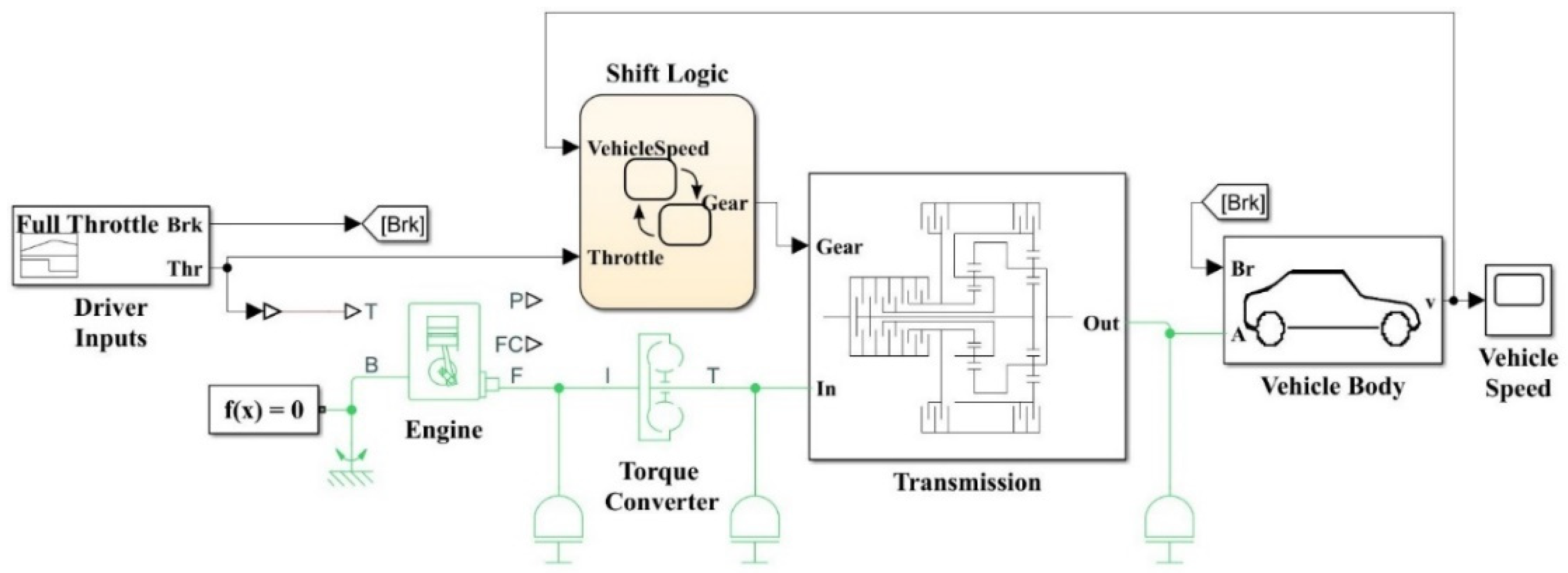
3.1. Mathematical Modeling of Autonomous Vehicle
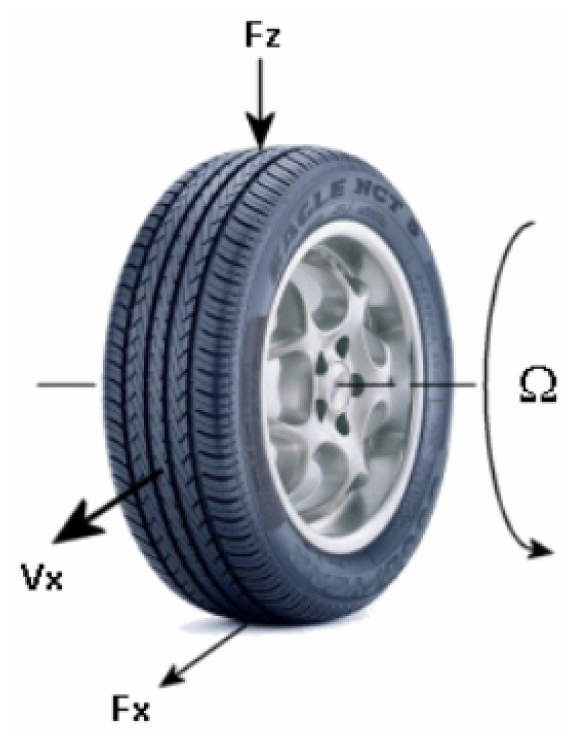
This section describes the mathematical modeling of the autonomous vehicle. The Tire (Magic Formula) block simulates a tire with longitudinal behavior described by the Magic Formula [23], an empirical equation based on four fitting coefficients. The block may represent tire dynamics under constant or varying pavement conditions.
The tire’s rolling motion on paved surfaces follows the same longitudinal direction. Based on the Tire-Road Interaction (Magic Formula) block [24], this block is a structural element.

3.1.1. Tire Model

The Tire (Magic Formula) block models the tire as a rigid wheel-tire combination in contact with the road and subject to slip. When torque is applied to the wheel axle, the tire pushes on the ground (while subject to contact friction) and transfers the resulting reaction as a force back on the wheel. This action pushes the wheel forward or backward. If you include the optional tire compliance, the tire also flexibly deforms under load. Figure 2 shows the forces acting on the tire [24].
Table 1 defines the tire model variables [25].

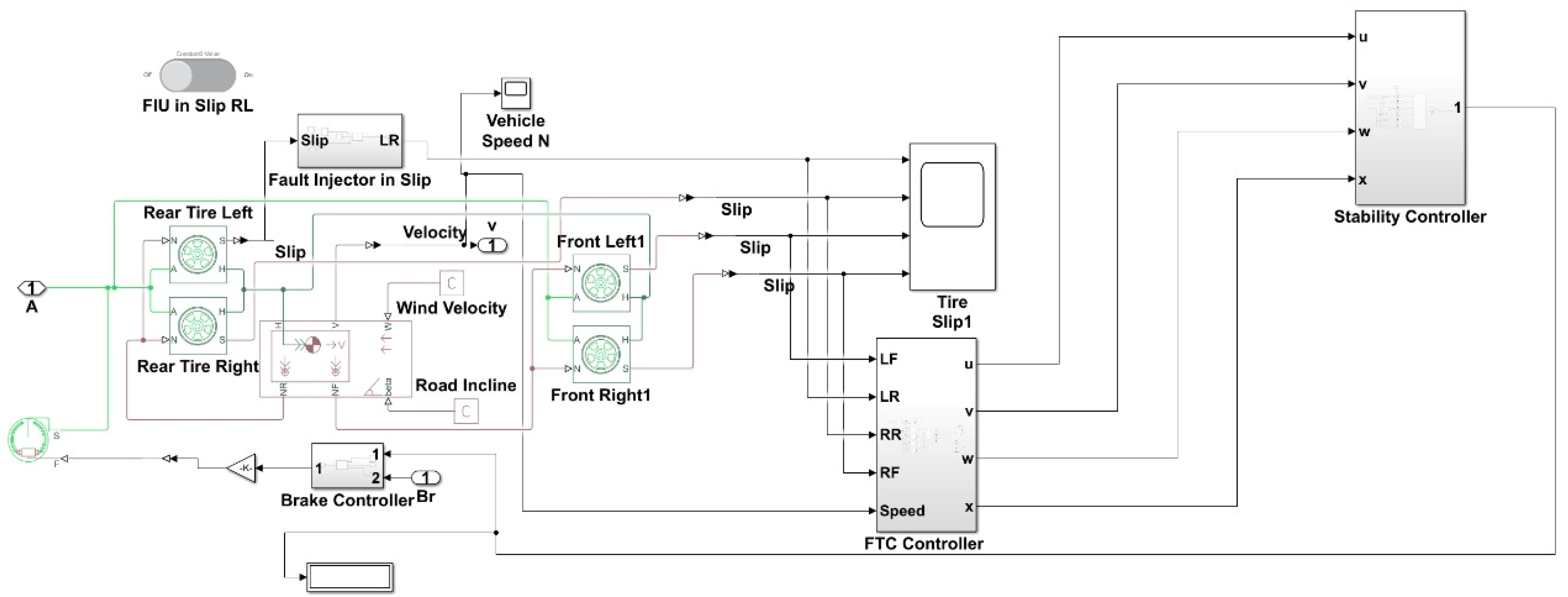
3.1.2. Modelling for Tire Slip

Figure 3 represents the model to calculate the slip of the tire. Slip errors only occur when there is an error in the tire due to which the rotational force on the tire is affected, and as a result, an accident may occur. So, to overcome this issue, a fault detection and isolation unit has been added to each tire slip so that if any error occurs in the slip, then to maintain the stability of the car, brakes are applied instantly so that damage can be minimized.
In normal conditions, the slip of the tires is nearly equal to zero. To check the stability and if the brakes are working, a fault was injected. As soon as the car starts to move and the fault is injected in wheel 1, the brakes start to work and the car begins to slow down, indicating the error in a slip of wheel 1.

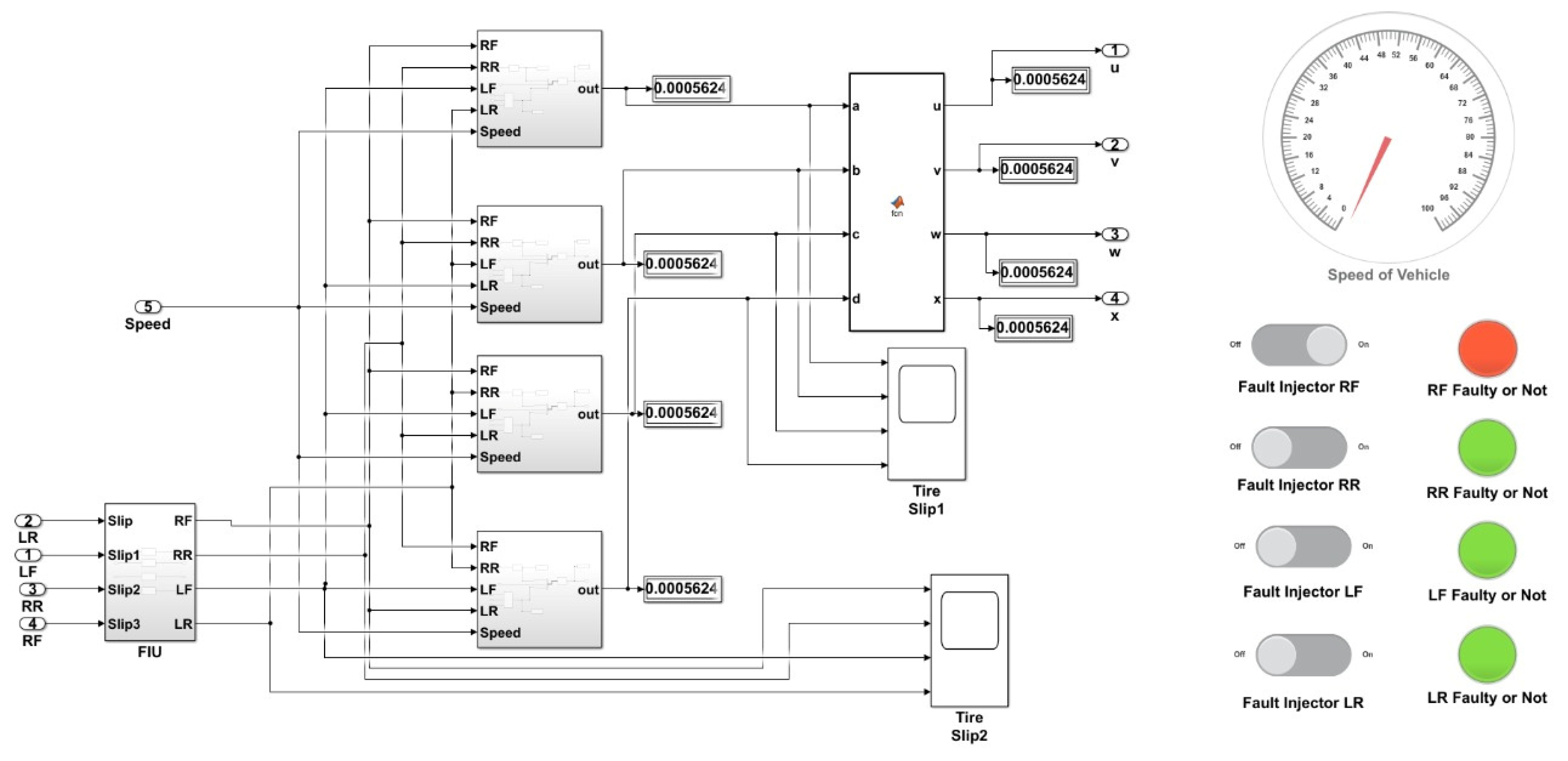
3.1.3. Modelling for Fault-Tolerant Controller

The benefit of the AFTC is that, rather than tolerating the issue or altering the baseline controller, the closed-loop control rejects the fault effect by using a dedicated FDI unit to assess the fault position and amplitude. The projection-based method and reconfiguration, often known as controller redesign, are the AFTC’s two key strategies. The FDI unit gives AFTC the ability to address a variety of problems. This is more practical and ideal for unforeseen problems (but their models must be recognized). The AFTC then becomes a topic for safety-critical systems such as self-driving cars on the ground. As part of ongoing research, numerous strategies have been examined in several applications. An active fault-tolerant control system is applied to autonomous vehicles, as shown in Figure 4. An observer is designed that estimates and predicts the values if any error occurs in the slip of any vehicle. In such conditions, if errors occur in the slip, then a fault-tolerant controller takes place and the observer sends the estimated value instead of the error value, due to which the autonomous electric vehicle keeps on moving and shows an error signal that should be replaced after the journey is over. So AFTC helps to solve the run time error issues that can arise in the wheel slip and thus improves the reliability of the system.

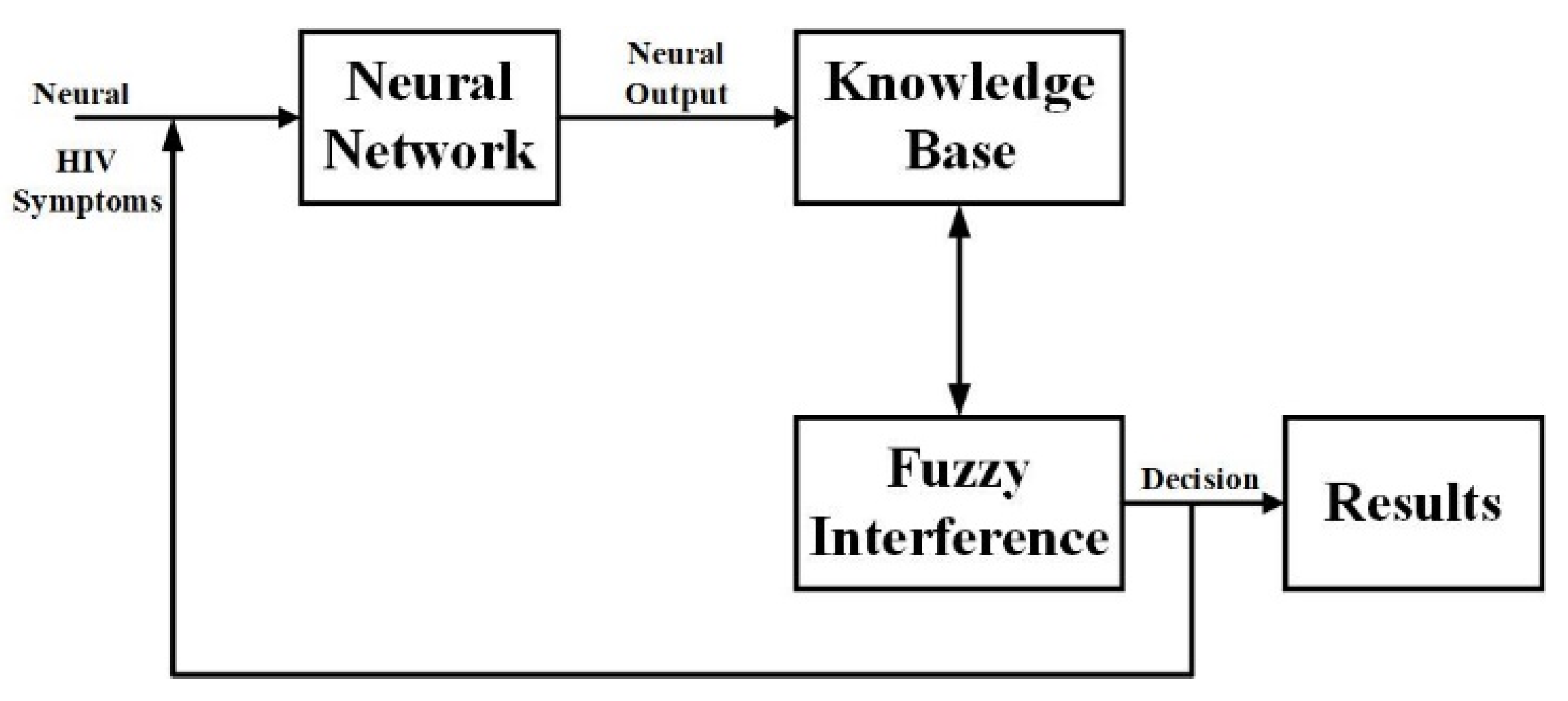
3.1.4. Fuzzy Neural Network Algorithm

The fuzzy control paradigm is one of the approaches to nonlinear system control (Figure 5). The Takagi–Sugeno (TS) representation is a method that represents plant nonlinearities by a sum of linear models weighted by weighting factors [26]. Consider the following nonlinear plant:
x ˙ t = f x t + g x t u t  
The TS representation of the equation above is given by:
x t = i = 1 r μ i ρ t A i x t + B i u t
where μi stands for the weighting functions, and ρ(t) stands for the membership parameters. The identification technique and the sector nonlinearity method are the two basic approaches for calculating weighting functions. Fuzzy control has become a popular study area in fault-tolerant control in recent years [27]. The simplicity with which stability analysis in closed-loop may be performed using the Lyapunov theory has inspired greater attention. Thus, in general, this technique is based on one of the fuzzy observer paradigms for the FDI task, and an augmented state space representation is derived by adopting the error dynamics between the output and the estimated state, in such a way that the fixed gains ensure the fuzzy controller and observer’s asymptotic stability [28].

3.1.5. Fuzzy Logic Controller

A well-known artificial intelligence-based control approach is fuzzy logic control (FLC). It makes use of the functionary’s prior knowledge of the target system. The primary responsibility of the functionary is to establish decision-based rules through system behavior analysis and language input variable analysis. Before producing the output, the inputs given to the FLC must go through the three fundamental processes of fuzzification, decision-making, and defuzzification. With the aid of specified membership functions (MFs), the input variable is turned into a linguistic variable during the fuzzification stage [29].
The result from the fuzzification step is then utilized to produce the output that has been fuzzified by the established ruleset. The fuzzified output is finally converted into the necessary output utilized for system control during the defuzzification stage. The FLC does require the exact model of the system throughout its construction, which is the most intriguing element of it. For systems with significant levels of uncertainty and nonlinearity, The FLC has a wide range of applications in the field of machine control.
The fuzzy logic controller is being used in this model for tracking the values of the slip of all the tires (Figure 6). In the proposed system firstly, the fuzzy controller is trained by getting the values from previous slip tires to train the observer to generate a random estimate value after providing it with almost 5000 data sets, as shown in Figure 7 and Figure 8 [30]. These data set values to help generate a value of the virtual sensor closer to the slip values so that if any error occurs in the slip, then instead of stopping the car an estimated value from the observer is sent so that the electric autonomous vehicles keep on moving and shows an error for a slip that could be replaced after the completion of the journey.

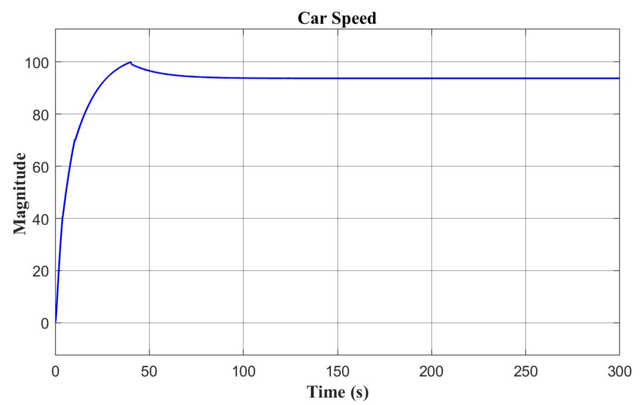
4. Results and Discussions

While driving an autonomous vehicle, the main aim is to stabilize the vehicle to overcome the possibility of accidents that may occur. Figure 9 shows the speed of the autonomous vehicle that is moving at a constant speed of 100 mph. As the system was turned on, the car started to move and after a certain period attains a constant speed. Figure 9 shows that there is no error in the vehicle, and it has moved smoothly toward the required speed.
Figure 10 shows the results in a tire slip that is nearly equal to zero. A pre-defined value has been set for the slip to be equal to zero if the electric vehicle is moving smoothly without any error, and if any error occurs in any vehicle, the display outputs a value of 2 and adds 0.1 if there occur any errors in the slip.
A fault was injected in wheel 1 to observe its impact on the speed. As soon as the fault was injected into the wheel slip, the value of 0.1 was added to the slip of the tire and the value for the brake was shown as 2, which started to slow down as shown in Figure 11.
As soon as the fault is detected in the slip of any tire, at that moment, the brakes are applied to avoid an accident. The speed for the brakes has been set at 0.5 value so that the brakes are applied slowly to avoid slipping or accidents with the INR. The autonomous vehicle’s speed starts to decrease and reaches a speed of 20 mph, as shown in Figure 12.
To see the speed of the vehicle, a display has been made that contains a speedometer along with an FDI unit that informs about fault injection and the speed of the car on which it is moving at run time. Such a dashboard helps the observer to see the stats in real-time on which the vehicle is moving; the dashboard and the speedometer are shown in Figure 13.
The main aim of our research was to apply fault-tolerant on the autonomous vehicle so if any error occurs in the slip of the tires, then instantly fault-tolerant control takes place and instead of stopping the car, it keeps on moving with the help of the observer values that have been generated with the help of estimated values provided by the fuzzy controller. To carry out this process we used a fuzzy logic controller that was trained with the help of more than 5000 values of sets that were provided by running the model, again and again, to obtain estimated values. If any slip sensor stops working, it can generate random values or wrong values and send them instead, so the car keeps on moving for a short interval of time and the journey can be completed. As soon as the sensor becomes faulty, the dashboard starts to show a red light, which means that the sensor has become faulty and should be replaced. This phenomenon keeps updating all slips and the car keeps on moving continuously as shown in Figure 14.
It is clear that after a fault was again injected the slip was not affected as the virtual sensor starts to send the estimated value, due to which the car moved at the same speed without any hassle, as shown in Figure 15.

5. Comparison with Existing Work

A comparison of the proposed autonomous vehicle has been performed with the existing works in this section. It was seen earlier that AFTC has increased the reliability and efficiency of the system due to the presence of a fuzzy controller that sends virtual values whenever the slip sensor fails. It has reduced the chances of a breakdown in the autonomous model by providing an alternative virtual sensor for continuous processes. The previous model was based on passive fault-tolerant control using multiple input and multiple output method that was only affected by predefined values, and as soon as any current error occurred, the system collapses and fails to overcome runtime errors. However, the proposed active fault-tolerant control system can continue operation even if errors occur at runtime. Additionally, it has a virtual sensor that sends estimated values if any sensors fail, to minimize the risk factor. Furthermore, the proposed work with the active type of fault-tolerant controller is novel and we could not find enough relevant literature to make a comparison table with already published similar works.

6. Conclusions

This paper presented an active fault-tolerant system operated on an autonomous vehicle, which is done on MATLAB/Simulink and can easily detect faults that occur in the slip sensor of the tire. It presented an active fault-tolerant control for autonomous vehicles with a fuzzy logic controller that can autonomously identify if there is any problem in the wheel speed to avoid accidents and maintain car stability. MATLAB/Simulink (version 2022a) was used for simulation experiments and the results demonstrate the stable operation of the wheel speed sensors to avoid accidents in the event of faults in the sensor or actuator if the vehicle becomes unstable. The presented works show that the proposed model is highly reliable and efficient with the addition of active fault-tolerant control that minimizes the error and helps to maintain vehicle stability.
Future work may include designing a controller for all the sensors that are attached along with each wheel, as it will improve and increase the accuracy and efficiency of the system and will increase the speed as well.

Author Contributions

Conceptualization, A.A.A.; Formal analysis, M.H.U.; Funding acquisition, T.A.; Investigation, M.H.U.; Methodology, A.A.A.; Project administration, A.A.A. and T.A.; Resources, A.A.A. and T.A.; Software, A.A.A. and T.A.; Supervision, A.A.A. and T.A.; Validation, A.A.A.; Visualization, A.A.A.; Writing—original draft, M.H.U.; Writing—review & editing, A.A.A. and T.A. All authors have read and agreed to the published version of the manuscript.

Funding

This research received no external funding.

Acknowledgments

The authors would like to thank their colleagues for their suggestions on how to improve the paper’s quality.

Conflicts of Interest

The authors declare no conflict of interest in preparing this paper.

Nomenclature

AbbreviationDescription
FTCFault-Tolerant Control
AFTCActive Fault-Tolerant Control
PFTCPassive Fault-Tolerant Control
4WIDFour Wheel Independently Driven
SMCSliding Mode Control
LPVLinear Parameter Varying
CAControl Allocation
MPCModel Predictive Control
SELMSequential Extreme Learning Machine
FTSFault-Tolerance Based Supervisor
FDIFault Detection and Isolation
CSControl Switching
IMMIntegration Multiple Model

References

  1. Wang, Y.; Ding, H.; Yuan, J.; Chen, H. Output-feedback triple-step coordinated control for path following of autonomous ground vehicles. Mech. Syst. Signal Process. 2019, 116, 146–159. [Google Scholar] [CrossRef]
  2. Wang, Y.; Gao, J.; Li, K.; Chen, H. Integrated design of control allocation and triple-step control for over-actuated electric ground vehicles with actuator faults. J. Frankl. Inst. 2020, 357, 3150–3167. [Google Scholar] [CrossRef]
  3. Zhang, G.; Zhang, H.; Huang, X.; Wang, J.; Yu, H.; Graaf, R. Active Fault-Tolerant Control for Electric Vehicles With Independently Driven Rear In-Wheel Motors Against Certain Actuator Faults. IEEE Trans. Control Syst. Technol. 2015, 24, 1557–1572. [Google Scholar] [CrossRef]
  4. Saleh, L.; Chevrel, P.; Claveau, F.; Lafay, J.-F.; Mars, F. Shared Steering Control Between a Driver and an Automation: Stability in the Presence of Driver Behavior Uncertainty. IEEE Trans. Intell. Transp. Syst. 2013, 14, 974–983. [Google Scholar] [CrossRef]
  5. Amin, A.A.; Hasan, K.M. A review of Fault Tolerant Control Systems: Advancements and applications. Measurement 2019, 143, 58–68. [Google Scholar] [CrossRef]
  6. Wang, B.; Huang, X.; Wang, J.; Guo, X.; Zhu, X. A robust wheel slip ratio control design combining hydraulic and regenerative braking systems for in-wheel-motors-driven electric Vehicles. J. Frankl. Inst. 2014, 352, 577–602. [Google Scholar] [CrossRef]
  7. Zhang, H.; Zhao, W.; Wang, J. Fault-Tolerant Control for Electric Vehicles With Independently Driven in-Wheel Motors Considering Individual Driver Steering Characteristics. IEEE Trans. Veh. Technol. 2019, 68, 4527–4536. [Google Scholar] [CrossRef]
  8. Smith, E.N.; Velenis, E.; Tavernini, D.; Cao, D. Effect of handling characteristics on minimum time cornering with torque vectoring. Veh. Syst. Dyn. 2017, 56, 221–248. [Google Scholar] [CrossRef]
  9. Aouaouda, S.; Chadli, M.; Boukhnifer, M.; Karimi, H.R. Robust fault tolerant tracking controller design for vehicle dynamics: A descriptor approach. Mechatronics 2015, 30, 316–326. [Google Scholar] [CrossRef]
  10. Alsuwian, T.; Amin, A.A.; Maqsood, M.T.; Qadir, M.B.; Almasabi, S.; Jalalah, M. Advanced Fault-Tolerant Anti-Surge Control System of Centrifugal Compressors for Sensor and Actuator Faults. Sensors 2022, 22, 3864. [Google Scholar] [CrossRef]
  11. Luo, Y.; Hu, Y.; Jiang, F.; Chen, R.; Wang, Y. Active Fault-Tolerant Control Based on Multiple Input Multiple Output-Model Free Adaptive Control for Four Wheel Independently Driven Electric Vehicle Drive System. Appl. Sci. 2019, 9, 276. [Google Scholar] [CrossRef] [Green Version]
  12. Aravindh, D.; Sakthivel, R.; Kaviarasan, B.; Anthoni, S.M.; Alzahrani, F. Design of observer-based non-fragile load frequency control for power systems with electric vehicles. ISA Trans. 2019, 91, 21–31. [Google Scholar] [CrossRef] [PubMed]
  13. Amin, A.A.; Mahmood-Ul-Hasan, K. Advanced Fault Tolerant Air-Fuel Ratio Control of Internal Combustion Gas Engine for Sensor and Actuator Faults. IEEE Access 2019, 7, 17634–17643. [Google Scholar] [CrossRef]
  14. Shen, H.; Xing, M.; Wu, Z.-G.; Xu, S.; Cao, J. Multiobjective Fault-Tolerant Control for Fuzzy Switched Systems With Persistent Dwell Time and Its Application in Electric Circuits. IEEE Trans. Fuzzy Syst. 2019, 28, 2335–2347. [Google Scholar] [CrossRef]
  15. Sakthivel, R.; Mohanapriya, S.; Kaviarasan, B.; Ren, Y.; Anthoni, S.M. Non-fragile control design and state estimation for vehicle dynamics subject to input delay and actuator faults. IET Control Theory Appl. 2020, 14, 134–144. [Google Scholar] [CrossRef]
  16. Wang, Y.; Zong, C.; Li, K.; Chen, H. Fault-tolerant control for in-wheel-motor-driven electric ground vehicles in discrete time. Mech. Syst. Signal Process. 2019, 121, 441–454. [Google Scholar] [CrossRef]
  17. Amin, A.A.; Mahmood-ul-Hasan, K. Robust passive fault tolerant control for air fuel ratio control of internal combustion gasoline engine for sensor and actuator faults. IETE J. Res. 2021, 1–16. [Google Scholar] [CrossRef]
  18. Tamaddoni, S.H.; Taheri, S.; Ahmadian, M. Cooperative DYC system design for optimal vehicle handling enhancement. In Proceedings of the 2010 American Control Conference, Baltimore, MD, USA, 30 June–2 July 2010; pp. 1495–1500. [Google Scholar]
  19. Amin, A.A.; Mahmood-Ul-Hasan, K. Hybrid fault tolerant control for air–fuel ratio control of internal combustion gasoline engine using Kalman filters with advanced redundancy. Meas. Control 2019, 52, 473–492. [Google Scholar] [CrossRef]
  20. Shen, H.; Dai, M.; Luo, Y.; Cao, J.; Chadli, M. Fault-Tolerant Fuzzy Control for Semi-Markov Jump Nonlinear Systems Subject to Incomplete SMK and Actuator Failures. IEEE Trans. Fuzzy Syst. 2020, 29, 3043–3053. [Google Scholar] [CrossRef]
  21. Maestre, J.M.; de la Peña, D.M.; Camacho, E.F. Distributed model predictive control based on a cooperative game. Optim. Control Appl. Methods 2010, 32, 153–176. [Google Scholar] [CrossRef]
  22. Complete Vehicle Model—MATLAB & Simulink—MathWorks India. Available online: https://in.mathworks.com/help/sdl/ug/about-the-complete-vehicle-model.html (accessed on 22 February 2022).
  23. Nguyen, B.H.; Nguyen, D.; Thanh, V.D.; Minh, C.T. An EMR of Tire-Road Interaction Based-On “Magic Formula” for Modeling of Electric Vehicles. In Proceedings of the 2015 IEEE Vehicle Power and Propulsion Conference, Montreal, QC, Canada, 19–22 October 2015; pp. 1–5. [Google Scholar]
  24. Tire-Road Dynamics Given by Magic Formula Coefficients—MATLAB—MathWorks India. Available online: https://in.mathworks.com/help/sdl/ref/tireroadinteractionmagicformula.html (accessed on 22 February 2022).
  25. Zhang, B.; Lu, S. Fault-tolerant control for four-wheel independent actuated electric vehicle using feedback linearization and cooperative game theory. Control Eng. Pract. 2020, 101, 104510. [Google Scholar] [CrossRef]
  26. Riaz, U.; Amin, A.A.; Tayyeb, M. Design of active fault-tolerant control system for Air-fuel ratio control of internal combustion engines using fuzzy logic controller. Sci. Prog. 2022, 105, 00368504221094723. [Google Scholar] [CrossRef]
  27. Na, X.; Cole, D.J. Game-Theoretic Modeling of the Steering Interaction Between a Human Driver and a Vehicle Collision Avoidance Controller. IEEE Trans. Hum.-Mach. Syst. 2014, 45, 25–38. [Google Scholar] [CrossRef]
  28. Espitia, H.; Machón, I.; López, H. Design and Optimization of a Neuro-Fuzzy System for the Control of an Electromechanical Plant. Appl. Sci. 2022, 12, 541. [Google Scholar] [CrossRef]
  29. Alsuwian, T.; Riaz, U.; Amin, A.A.; Qadir, M.B.; Almasabi, S.; Jalalah, M. Hybrid Fault-Tolerant Control for Air-Fuel Ratio Control System of Internal Combustion Engine Using Fuzzy Logic and Super-Twisting Sliding Mode Control Techniques. Energies 2022, 15, 7010. [Google Scholar] [CrossRef]
  30. Train Adaptive Neuro-Fuzzy Inference Systems—MATLAB & Simulink—MathWorks India. Available online: https://in.mathworks.com/help/fuzzy/train-adaptive-neuro-fuzzy-inference-systems-gui.html (accessed on 22 February 2022).
Figure 1. Simulation model of autonomous vehicle [22].
Electronics 11 03165 g001
Figure 2. Tire model with wheel variables [24].
Electronics 11 03165 g002
Figure 3. Tire Slip Calculation Model.
Electronics 11 03165 g003
Figure 4. Active fault-tolerant controller applied on the autonomous vehicle.
Electronics 11 03165 g004
Figure 5. Nero-fuzzy system model.
Electronics 11 03165 g005
Figure 6. Fuzzy logic controller for estimated slip value calculation.
Electronics 11 03165 g006
Figure 7. Data set values for the training of the fuzzy neural network.
Electronics 11 03165 g007
Figure 8. Data set values for the training of the fuzzy neural network.
Electronics 11 03165 g008
Figure 9. Autonomous vehicle speed profile without any fault.
Electronics 11 03165 g009
Figure 10. Tire Slip error without fault.
Electronics 11 03165 g010
Figure 11. Tire slip error after fault injection in Wheel 1.
Electronics 11 03165 g011
Figure 12. Autonomous vehicle speed after fault injection in Wheel 1.
Electronics 11 03165 g012
Figure 13. Speedometer to check car speed at run time.
Electronics 11 03165 g013
Figure 14. Tire Slip Error after fault tolerance with proposed AFTC in faulty conditions.
Electronics 11 03165 g014
Figure 15. Autonomous vehicle speed after fault tolerance with proposed AFTC.
Electronics 11 03165 g015
Table 1. Parameters to calculate slip of tire.
SymbolDescription and Unit
r w Wheel Radius
V x Wheel hub longitudinal velocity
u Tire longitudinal deformation
ΩWheel angular velocity
  Ω Contact point angular velocity. If there is no tire longitudinal deformation, that is
u = 0,   Ω = Ω
r w   Ω Tire thread longitudinal Velocity
V x x = r w Ω V x Wheel slip velocity
V x x = r w Ω V x Contact slip velocity. If there is no tire longitudinal deformation, that is
u = 0, V x x = V x x
k = V x x   V x   Wheel slip
k = V x x   V x   Contact slip. If there is no tire longitudinal deformation, that is
u = 0, k = k
V t h Wheel hub threshold velocity
F z Vertical load on the tire
F x The longitudinal force exerted on the tire at the contact point
C f x = ( F x u ) Tire longitudinal stiffness under deformation
B f x = ( F x u ) Tire longitudinal damping under deformation
I w Wheel-tire inertia, such that the effective mass is equal to I w r 2 w
τ d r i v e Torque applied by the axle to the wheel
Publisher’s Note: MDPI stays neutral with regard to jurisdictional claims in published maps and institutional affiliations.

