1. Introduction
Metasurfaces are artificial electromagnetic (EM) materials with properties that beyond natural limitations, and can manipulate the amplitude, phase, and polarization [
1] states of reflected and transmitted EM waves at will. They are typically made of periodically arranged subwavelength unit cells whose properties are determined by the unit cell structure geometry and the dielectric substrate. Thus, the properties of a material are limited by its structure. The emergence of active metasurfaces solves the problem of characteristic curing. Active components with controllable properties such as PIN diodes, MEMS, and graphene are used in structural design to manipulate the response of metasurfaces [
2,
3,
4]. The applications of active metasurfaces are greatly broadened. Some exotic scattering phenomena of metasurfaces are also of particular interest.
Time-variant properties are a critical method to breaking reciprocity that imposes fundamental limitations on wave propagation [
5,
6]. The harmonic effects of electromagnetic waves irradiated on time-modulated metasurfaces have been studied in depth. Dispersionless phase shift [
7] and fundamental/harmonic cancellation [
8] methods have been proposed. In addition, some researchers realized serrodyne frequency conversion [
9] and artificial Doppler frequency shift [
10,
11] based on a phase-switched screen (PSS). Harmonic effects of time-modulated metasurfaces are also widely used in radar. Periodic time-modulated PSS is used for concealment of real targets in ISAR images [
12]. It shows not only the concealment of the real target, but also the multi-target simulation in the ISAR image [
11,
13]. Active frequency selective surface (AFSS) is used to modulate the scattering mechanism of the target, generating multiple fake targets on the SAR image and the phenomenon of distance transformation of a single target [
14,
15].
The above studies demonstrate the effectiveness of phase and amplitude modulation in radar stealth and radar jamming, respectively. In fact, the polarization conversion metasurface enables both phase and amplitude modulation. Nowadays, several studies have revealed a time-modulated polarization conversion metasurface (APCM). Dai et al. proposed a harmonic control method for metasurfaces under time modulation [
16] Arbitrary polarizations can be realized based on APCM using the time modulation method [
17]. Time-modulated APCM is used to build communication links [
18]. However, the radar effects of the phase-amplitude joint modulation have not been fully studied. The relationship between modulation parameters and modulation effects is not clear.
Inspired by this idea, an amplitude-phase joint modulation method based on polarized rotating surfaces is proposed for generating virtual targets. In
Section 2, a modulation method based on APCM is presented. Taking the radar echo as the research object, the amplitude and phase characteristics of the
k-th virtual target after modulation are analyzed in detail. The relationship between parameters such as phase modulation range and absorbing depth and the characteristics of the virtual target is revealed in
Section 3.
2. Time-Domain Amplitude-Phase Joint Modulation Model
Figure 1 shows the principle of time-domain amplitude-phase joint modulation (TAJM) model. Active polarization conversion metasurfaces enable simultaneous amplitude and phase manipulation.
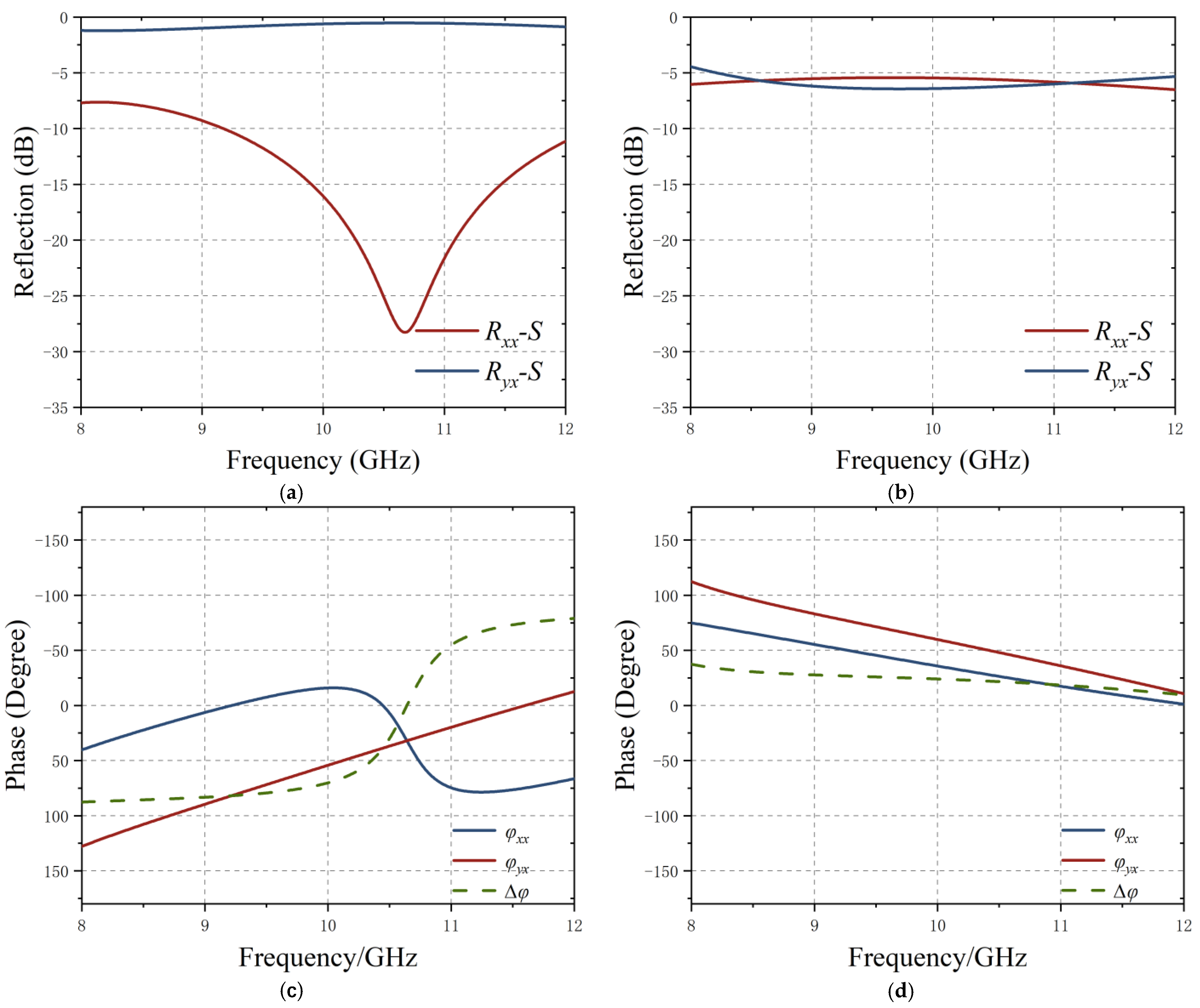
The structure and response of a typical polarized spin metasurface are shown in
Figure 2 and
Figure 3. Observing from a single polarized channel, PIN diode state switching can change the magnitude and phase of the reflection coefficient simultaneously. In order to simplify the content, the subsequent research in this paper is based on the single polarization response of APCM.
Figure 3a–d show the response curves of the APCM in different states. The bias voltage is varied over time so that the reflection coefficient is a function of time
Γ(
t). The active metasurface is controlled by FPGA to obtain the time-varying response characteristic
Γ(
t). The radar EM wave illuminates the metasurface and obtains the reflected signal
R(
t).
Γ(
t) is defined to represent the reflection coefficient
where
p(
t) and
φ(
t) represent amplitude and phase, respectively. The functions of
p(
t) and
φ(
t) can be written as
x1 and
x2 are the reflection coefficient amplitudes in the two states, respectively, and
φ1 and
φ2 are the reflection phases, respectively.
α represents the duty cycle of the rectangular pulse train (0 <
α < 1),
T is the period, and
ε(
t) is the step function. The magnitude and phase of the reflection coefficient are shown in
Figure 1b,c. Since the reflection coefficient
Γ(
t) is a periodic signal, (1) can be expressed as a Fourier series
where Ω = 2
π/
T implies that the angular frequency is determined by the period
T of
Γ(
t), and
ak denotes the corresponding Fourier-series coefficient. The equation of the echo signal can be written as
R(
t) =
S(
t)·
Γ(
t).
R(
t) and
S(
t) denote the reflected and incident signal, respectively. The corresponding spectrum of the echo signal can be described by
From (1)–(3), the harmonic coefficient is given by
It is worth noting that when α = 0.5, the reflected signal has only odd harmonics, and the amplitude of even harmonics is 0. M1 = x1(1 − α), M2 = x2α.
3. HRRP Effect Analysis and Discussion
Radar high resolution range profile (HRRP) represents the amplitude of the coherent summations of the complex time returns from target scatterers in each range cell. It represents the projection of the complex returned echoes from the target scattering centers onto the radar line-of-sight (LOS), reflecting the important characterization of the target. The multiple polarimetric channels are used to obtain fully polarimetric data.
It should be noted that HRRP is a complex exponential signal, including amplitude information and phase information of target scattering. The matched-filter output is the fully polarization HRRP modulated by the metasurface. Radar detection systems often use linear frequency modulation (LFM) signal as the waveform of the transmitted signal. The LFM pulse waveform is adopted as the incident signal
S(
t) in this paper. It is with carrier frequency
fc, pulse width
TP, signal bandwidth B, pulse repetition interval T, and chirp rate
Kr =
B/
Tp.
S(
t) is given by
According to Principle of stationary phase (POSP), a simplified frequency domain expression
S(
f) of the incident signal can be expressed as [
19]
The periodic modulation produced by the metasurface spreads the energy of the echo signal at harmonic positions,
fs = 1/
T. If
fs >
B, the energy will be scattered outside the acceptable spectrum range. However, when
fs <
B, the modulation effect of the metasurface will have a significant impact on the signal processing of the receiver. The effect of the
fs <
B case on the echo signal processing is analyzed. The matched filter of the transmit signal
S(
t) is
H(
f) =
S*(
f). When the echo signal is received, the inverse Fourier transform is performed after matched filtering to obtain the time domain response
y(
t) = IFFT[
S(
f)·
H(
f)]
The ambiguity function of the HRRP signal is expressed as
which Sa(x) = sin(
x)/
x,
ysk(
t) is rewritten as
In order to visualize the effect of false target generation by TAJM, the simulation calculation of 2D SAR images was performed.
Figure 4 shows the simulation result of 2D SAR images of the single point target which is modulated by TAJM method with
fs = 15 MHz. In the
Figure 4, the multi-target phenomenon can be observed with a total of five targets. Four virtual targets are symmetrically distributed on both sides of the original target. Next, the multi-target and distance transformation phenomena are analyzed in terms of the distance-oriented profile at the location of the target scattering center.
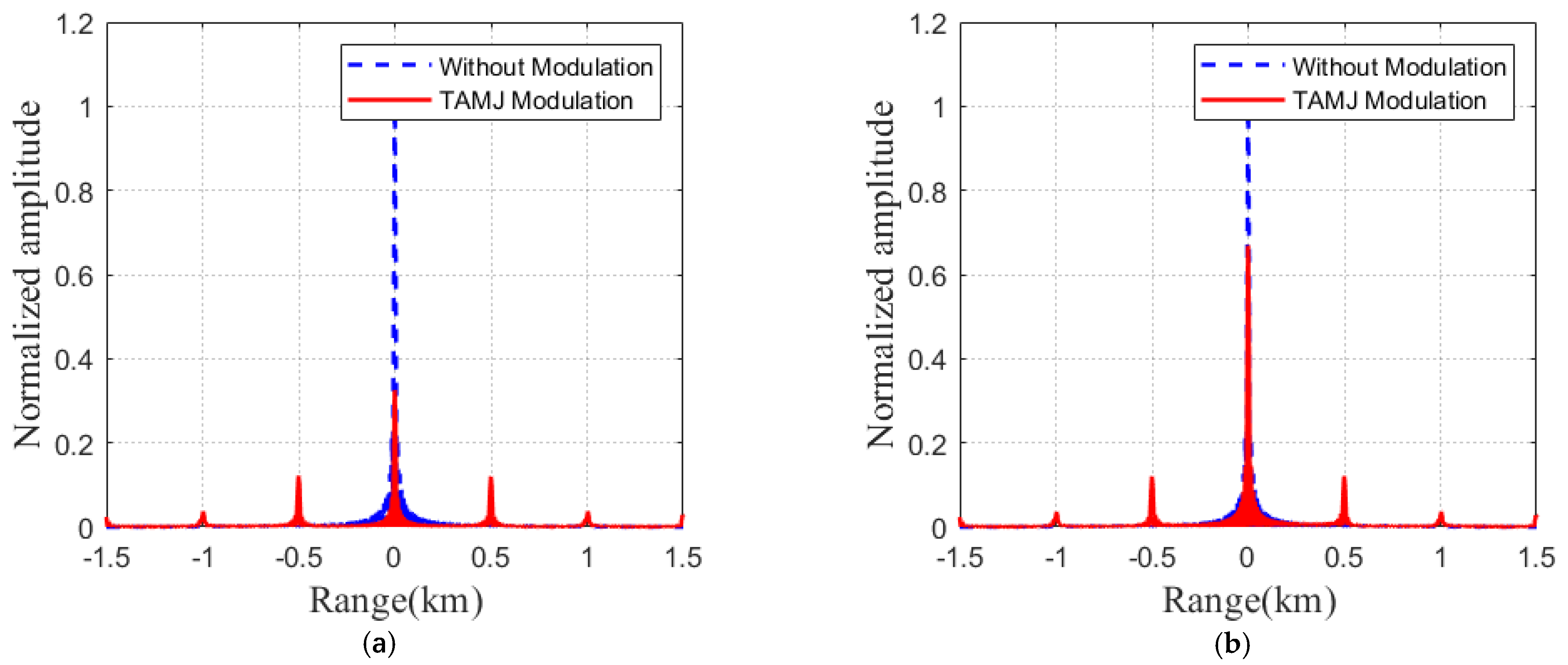
Figure 5 shows the matched-filter output of the co-polarization and cross-polarization channels when
fs = 5 MHz and
α = 0.6. In
Figure 5, the original target still retains the inherent scattering properties. Multi-virtual targets generated by TAJM are distributed at equal intervals around the original target. However, the signals of other targets are arranged at equal intervals on both sides of the origin. These targets do not actually exist and are false targets generated after modulation. The information of the false target conforms to the (11). These targets have different scattering properties than the target at the origin.
The
ysk(
t) contains target information. When
t = −
kfs/
Kr,
ysk(
t) takes the maximum value. By (10),
Pk = −
kfsv/
K is the position where the
k-th target peak appears. The position
Pk is only related to the modulation frequency of the modulation signal. When the duty cycle of the modulation signal is 0.5, and the even-order
ak is 0, false targets can only be observed at odd-order positions. The magnitude
Ak of the
k-th order false target is
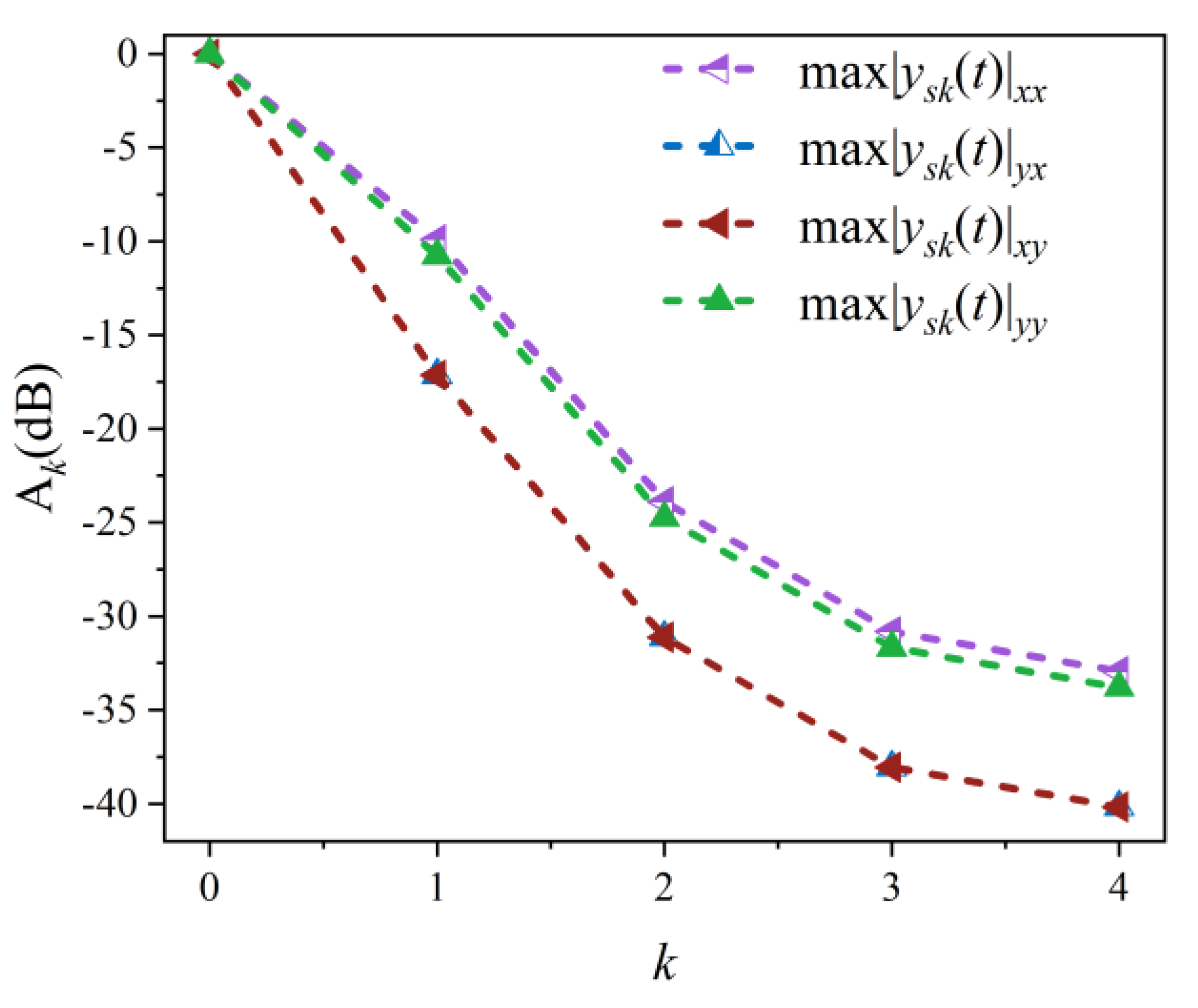
Figure 6 shows the
k-th order peaks of the echo signals of the four polarization channels. The modulation frequency is
fs = 5 MHz and the duty ratio
α = 0.6. Energy is mainly concentrated on low-order targets,
Ak decrease as
K increases, so subsequent analysis focuses on low-order peaks.
K is the modulation frequency of the LFM signal, which is determined by the transmitted signal. (1 − |
kfs/
B|) represents the mismatch degree of the matched filter when the reflected signal has a Doppler frequency shift of
kfs. The
ak is the Fourier expansion term coefficient of the TAJM signal
Γ(
t), which is affected by the phase
φ, amplitude
x and duty cycle
α of
Γ(
t). The following part analyzes the effect of phase difference ∆
φ =
φ2 −
φ1, amplitude difference ∆
x =
x2 −
x1, and duty cycle
τ on
Ak.
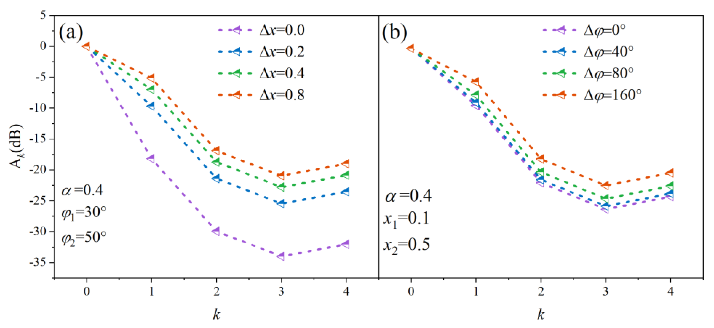
Figure 7a shows the relationship between the peak normalized amplitude of k-order false target and different ∆
x (0 < ∆
x < 1) when the phase and duty cycle are fixed. The calculated results represent the relative amplitudes of the
k-order peaks, and the amplitude difference of each order peaks decreases as Δ
x increases. That is, the larger Δ
x is beneficial to distribute the energy evenly at the higher order harmonics. The effects of different ∆
φ on the normalized peaks amplitude of each order when
τ and
x1 and
x2 are fixed are shown in
Figure 7b. It can be concluded that ∆
x significantly affects the energy distribution, while ∆
φ has less effect.
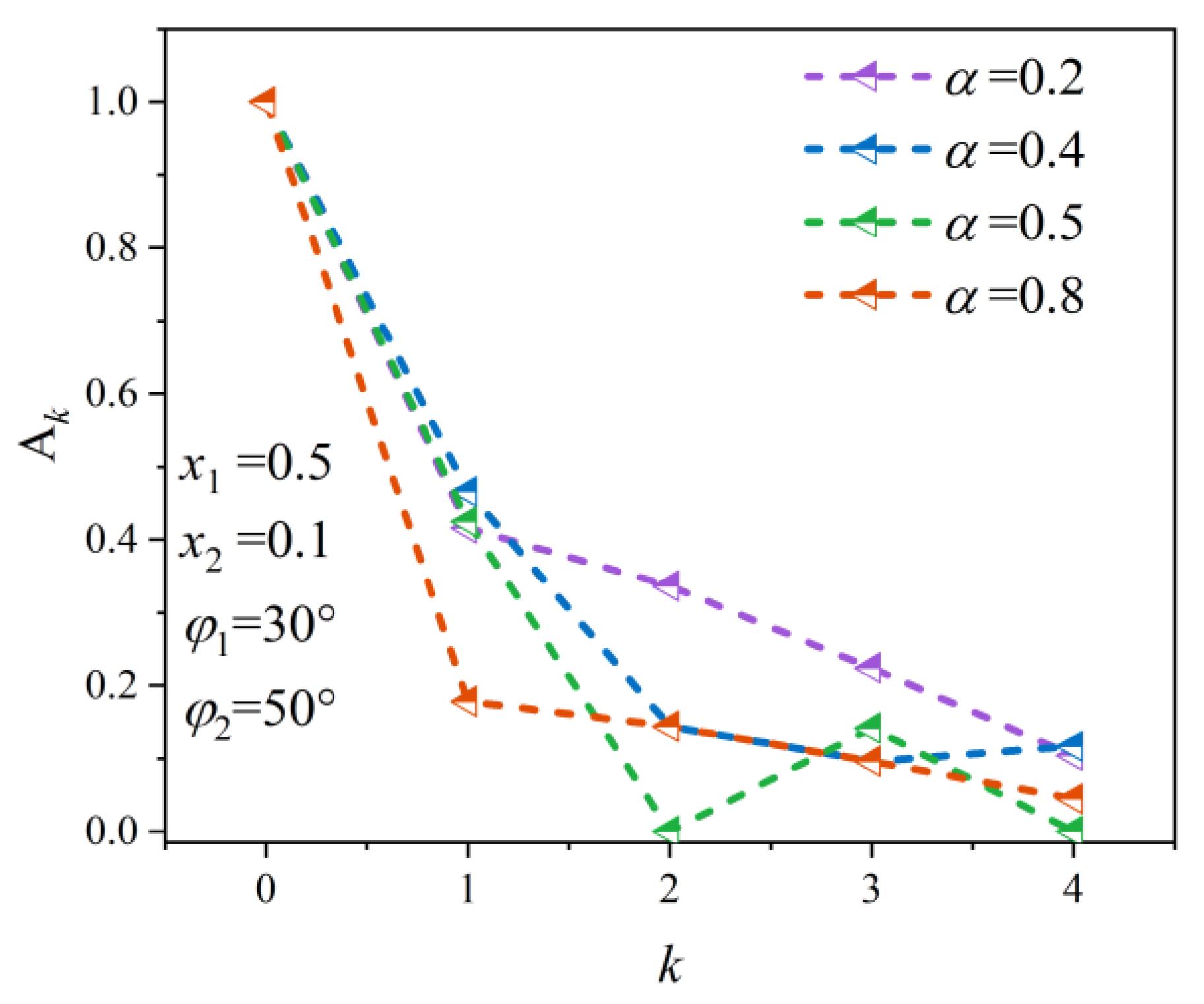
In
Figure 8, the duty cycle
α has a significant effect on the target normalized peak amplitude. When
α = 0.5, only odd-order peaks exist, that is consistent with the theoretical analysis. When
α increases from 0.2 to 0.8, the energy of the reflected signal gradually concentrates to the 0-th order peak. For
k-th order peaks (
k ≠ 0), the energy difference between peaks decreases as the
τ increases.
Figure 9 shows the effect of changes in modulation signal parameters on the phase. According to the results, Δ
x, Δ
φ, and
α can significantly affect the phase of the reflected signal. There is a clear difference between the phases of zero- and first-order harmonics. The phase offset of the non-zero order is proportional to the order
k.
Figure 4,
Figure 5,
Figure 6,
Figure 7 and
Figure 8 fully illustrate that the modulation method based on TAJM can generate false targets in one-dimensional HRRP. At the same time, the amplitude and phase of HRRP can be manipulated by changing the parameters of the modulating signal.


