1. Introduction
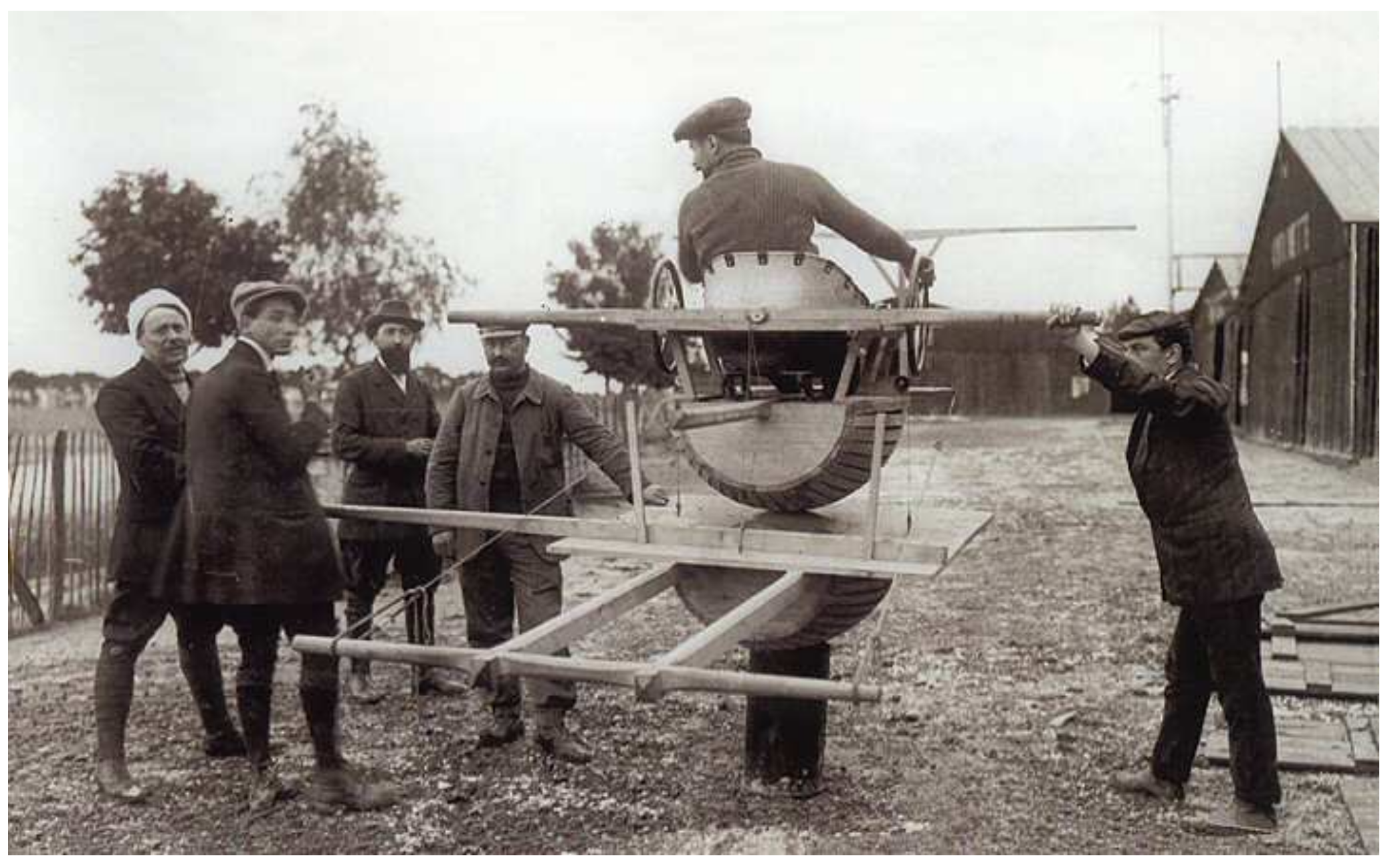
Simulators with a human being in the loop appeared during the aviation era (around World War I) for pilot training. The “Tonneau Antoinette” flight simulator, pictured in
Figure 1, is a notable example. It was used for ground training by the French Air Force.
Driving simulation is another field in which simulators with a human being in the loop can be found. The aim, in this case, is to give a driver the illusion of driving a vehicle. Driving simulation is mainly used in the following three areas, with different objectives and means: research and development in the automotive industry; studies and research on driving behavior; and (re-)training. Driving simulators consist of the following two parts: (1) the simulated vehicle; and (2) the simulation environment, i.e., the road network and the various actors of the situation. The driver in the loop operates the virtual vehicle composed of a vehicle mock-up and a vehicle model. Both the mock-up and the model can vary in their degree of complexity. In particular, the vehicle cabin can be fixed-based or motion-based, with various possible movements and a varying number of sensors and actuators. A simulator with a motion-based vehicle cabin is called a dynamic simulator.
It is possible to design simulators of different vehicles; however, rendering the vehicle dynamics at scale one is particularly difficult or costly. Car manufacturers currently use high-end simulators able to approach scale one for lane-change maneuvers (i.e., for lateral dynamics). However, they are still limited by the simulators’ size for longitudinal dynamics. The question is much more complex for motorcycles. A critical issue (among others) for the design of motorcycle simulators is the impossibility of rendering the centrifugal and centripetal forces for both right-hand and left-hand bends.
A system with a human being in the loop is defined in opposition to a system designed to work “next to” the human user. The operator must be identified and integrated as part of the loop for the whole system to be acceptable from the human’s point of view. The acronym HUIL (human-in-the-loop) simulation, which can be found in the literature, describes this type of system. This abbreviation should, in our opinion, be employed rather than HIL or HITL, which can also describe hardware-in-the-loop simulation (i.e., testing real hardware in a simulation loop, whereas in our case, we are testing a human being in a simulation loop).
2. Research Questions
For all HUIL simulators, it is necessary to instrument the system for the following two purposes: (1) to capture the operator’s actions; and (2) to provide them with sensory feedback.
Figure 2 illustrates the general structure of a HUIL driving simulation. The driver remotely operates a vehicle model via a mock-up, which is fundamentally different from driving a vehicle. The more closely the driver interacts with their vehicle to control its trajectory, the more difficult the driving is to simulate. For cars, the interactions are mainly through the steering wheel, while for two-wheeled vehicles, the interactions are much more complex, due to the constraint of maintaining the vehicle’s equilibrium.
From the simulated vehicle’s point of view, the driver’s actions, i.e., the model’s inputs, are perceived using sensors. The vehicle’s reactions to these stimuli, i.e., the model’s outputs, are rendered using actuators. The driver perceives these reactions in terms of sensory feedback, including visual, kinesthetic, haptic, and auditory feedback. From the driver’s point of view, sensory feedback is sensor data.
A first challenge for designing a HUIL driving simulator is its instrumentation, as the human driver is both the initiator of the physics (kinematics and dynamics of the motion) and the receptor of the various feedback resulting from their actions. A second challenge is to provide feedback to the driver that matches their expectations according to their driving experience (this is called the internal model; for more on this, please see the literature on human motor control research [
2,
3,
4,
5,
6,
7,
8,
9]). Incongruence between the reactions of the system and the human driver’s expectations may induce simulator sickness [
10,
11,
12], which may, in turn, lead to bias in the results acquired using driving simulators. On the contrary, the congruence between the reactions of the system and the human driver’s expectations guarantees the acceptability of the system from the driver’s point of view.
This article presents a rider-in-the-loop dynamic motorcycle simulator. Very few motorcycle-riding simulators exist today. Some examples are the Honda simulator [
13], the MORIS simulator of the Perceptual Robotics Laboratory of the School of Advanced Studies of Pisa [
14], the simulator of the Mechanical Engineering Department of the University of Padua [
15], the DESMORI simulator of the Würzburg Institute for Traffic Sciences [
16] and the MOTORIST simulator of the Delft University of Technology [
17]. They have been designed to fulfill different objectives, with varying approaches depending on factors such as the desired application and the areas of expertise of the researchers who designed them. For this reason, they cannot really be compared. However, to the best of our knowledge, only a very small portion of the literature describes design strategies for motorcycle simulators. The existing research is mainly focused on addressing mechanical and dynamic design constraints and not on system instrumentation. This is why we suggest an approach focused on human acceptability, which can accommodate other design specifications. We believe that human acceptability is a crucial point for all applications of motorcycle simulators. If the simulator is not acceptable for the rider (and thus accepted by them), then the acquired results’ validity is in question.
Our goal is to design a rider-in-the-loop dynamic motorcycle simulator and validate the rider acceptability of all its sub-systems and the system as a whole. In order to do so, the first part of our work was to understand the feedback loop centered on the human rider. Identifying the rider’s behavior, particularly their reactivity, is necessary to integrate them as part of the system, while guaranteeing its acceptability.
We argue that simulator sickness, which is a prominent sign of the simulator not being acceptable, comes from a mismatch between the complexity of the vehicle model and the fidelity of the sensory cues reproduced by the simulator. We designed a proof-of-concept (POC) system to explore our hypothesis, focusing on rendering haptic cues on motorcycle handlebars [
1]. We then used this POC system in a pilot experiment with the following two purposes: (1) validating the rider acceptability of the designed motorized handlebars (with subjective measures); and (2) comparing controllability and task performance for a simple control task, depending on whether the complexity of the vehicle model and the fidelity of the sensory cues were coherent or mismatched [
18].
Studying human behavior when confronted with different modalities of interfaces with a virtual world allowed us to apprehend the insertion of the human in a simulator. In the second phase of our work, we aim to use this knowledge and combine it with instrumentation (sensors, actuators) constraints to design a simulator. The difficulty in a simulator is that there are physical and virtual sensor data to take into account. For example, in our simulator, the degrees of freedom (DOFs) are only rotations and no translations. Thus, the speed of the motorcycle is an entirely virtual piece of data; the speed sensor is in virtual space. Meanwhile, the acceleration data come from a physical sensor, the twist-grip accelerator. All sensor and actuator data must be physically and time coherent.
Here, we present the design of our motorcycle-riding simulator’s hardware/software architecture. The simulator consists of two dynamic bodies, the steering column and the chassis. In the following, we describe these bodies, their assembly, and their electronic interfaces. We focus, in particular, on the instrumentation of the motorcycle simulator. This instrumentation was designed to (1) capture the rider’s actions in real-time, (2) render the motorcycle’s behavior to the rider, and (3) measure and study rider/simulated motorcycle interactions. Our objective is to increase motorcycle-riding simulators’ rendering quality and propose a methodology for a simulator design with architecture/virtual vehicle model adequacy, which guarantees rider acceptability. The novelty of our work resides in this particular approach. We believe our methodology could be adopted by future designers of motorcycle-riding simulators and other HUIL simulators, regardless of the desired application of the simulator, because human acceptability is paramount in all cases. Our methodology is especially relevant for designing HUIL driving simulators when the vehicle’s trajectory is significantly related to the interactions between the driver and the vehicle, e.g., two-wheeled vehicles, such as motorcycles and new personal mobility vehicles, such as electric scooters.
3. Different Modalities for Sensors/Actuators Interfaces: Examples for a Motorcycle-Riding Simulator
HUIL driving simulators are very complex. In the context of a simulated physical world, any stimulus or set of stimuli produced by the driver (inputs of the simulator system measured by sensors) combines with (1) the physical reaction derived from the calculation of the model of the vehicle in its environment (output actions rendered by actuators) and (2) the intrinsic effects of the driver’s actions on the physical platform. Consequently, different interfaces can be used between the driver and the virtual world to capture the driver’s actions or render the vehicle’s actions and behaviors. In the following section, we use the notations for a sensor, for an actuator, for virtual, and for real. The sensors and actuators that are useful for a motorcycle-riding simulator can be classified as (using these notations) the following:
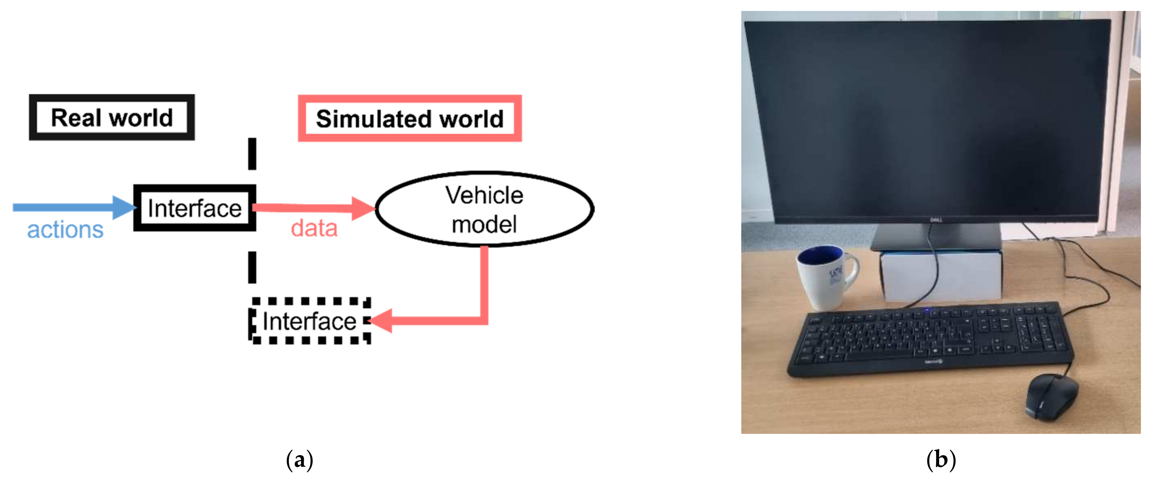
A “simple” interface with a virtual sensor (
) or virtual actuator (
), noted
. This interface type is represented schematically in
Figure 3a (using the same symbolism as
Figure 2).
Figure 3b shows examples of an
interface, including a screen, a mouse, and a keyboard.
Figure 3.
(a) Representation of a virtual sensor/virtual actuator interface (in blue: rider’s actions; in orange: data to and from the vehicle model); (b) examples of a virtual sensor/virtual actuator interface: screen, mouse, and keyboard.
Figure 3.
(a) Representation of a virtual sensor/virtual actuator interface (in blue: rider’s actions; in orange: data to and from the vehicle model); (b) examples of a virtual sensor/virtual actuator interface: screen, mouse, and keyboard.
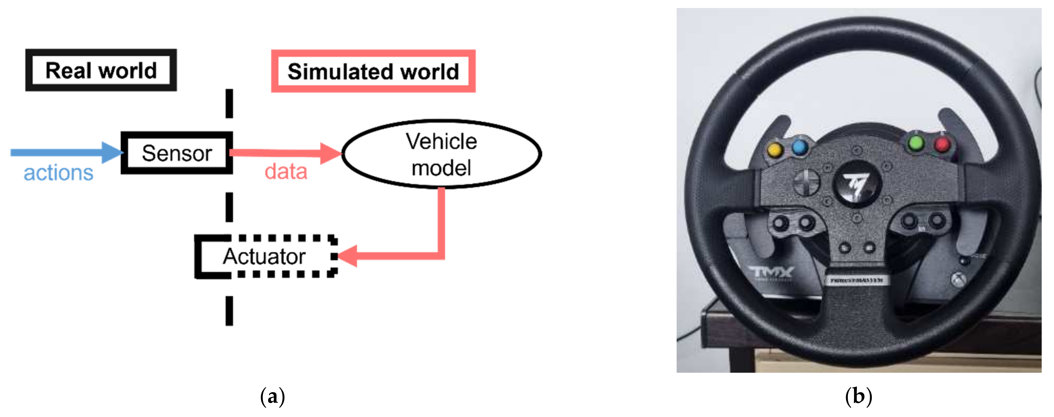
A real sensor (
) on its own or in conjunction with a virtual actuator (
). This type of interface (noted
) is represented schematically in
Figure 4a. One must note that a virtual actuator can be partially real, for example, if it provides kinesthetic or haptic sensory feedback to the operator.
Figure 4b shows an example of this interface type, a steering wheel joystick. We chose this example despite our interest in motorcycle-riding simulators because joystick handlebars are much less common. For this type of interface, there is no physical coupling between the sensor and the actuator.
Figure 4.
(a) Representation of a real sensor/virtual actuator interface (in blue: rider’s actions; in orange: data to and from the vehicle model); (b) an example of a real sensor/virtual actuator interface: a steering wheel joystick.
Figure 4.
(a) Representation of a real sensor/virtual actuator interface (in blue: rider’s actions; in orange: data to and from the vehicle model); (b) an example of a real sensor/virtual actuator interface: a steering wheel joystick.
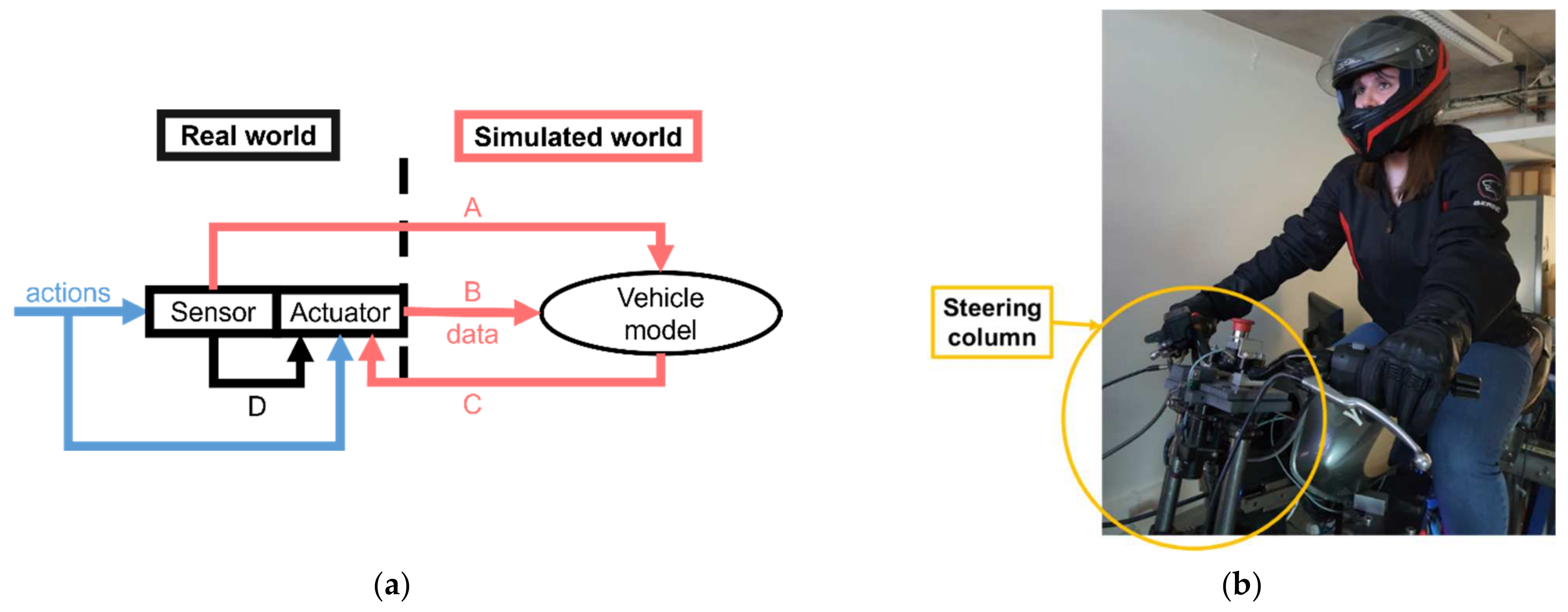
A real sensor (
) in conjunction with a real actuator (
). This type of interface (noted
) is represented schematically in
Figure 5a.
Figure 5b shows the steering column of our motorcycle-riding simulator, which is an example of this interface type. The steering column of our simulator is discussed in more detail in this article. For this type of interface, the sensor and actuator both provide data to the vehicle model (this is represented by relations A and B in
Figure 5a). Specifically, human actions produce sensor data (A) and intrinsic motion of the actuator, which becomes input data for the vehicle model (B: modifying the physical position). The vehicle model controls the actuator (C). Additionally, there is significant physical coupling between the sensor and the actuator (D).
Figure 5.
(a) Representation of a real sensor/real actuator interface (in blue: rider’s actions; in orange: data to (relations A and B) and from (relation C) the vehicle model; relation D: physical coupling); (b) an example of a real sensor/real actuator interface in our motorcycle-riding simulator: the steering column (copyright: TS2—SATIE—MOSS, Univ Gustave Eiffel).
Selecting interfaces for a simulator among these categories must be carried out according to the design specifications, e.g., application domain. One must note that if we were considering other types of HUIL simulators, we could have imagined other examples of interfaces, e.g., a PHANToM haptic interface. In the following section, we describe our motorcycle-riding simulator and classify its rider/virtual motorcycle interfaces using these categories.
4. Our Motorcycle-Riding Simulator
4.1. General Description
Our motorcycle-riding simulator (pictured during an experiment in
Figure 6) was initially developed in 2006 as part of the SIMACOM research project, supported by the French National Research Agency (ANR). It has since been used in several human-centered studies (most recently, in [
19,
20,
21,
22]) but is still a research object.
The simulator consists of the following elements:
Three large, fixed screens (55-inch TVs), assembled edge to edge to obtain a quasi-continuous visual field. The screens are arranged in the form of a pseudo-circle with the rider’s head as the center, providing a 130° field of view (1920 × 1080 pixels for each display, approximately 44 PPD);
A 5.1 sound system;
A motorized steering column (called dynamic body n°1 in the following sections) with the following two DOFs: force feedback handlebars and a pseudo-haptic feature that provides the rider with longitudinal acceleration/braking cues;
A complete motorcycle chassis, supported by a dynamic platform (dynamic body n°2) with the following three DOFs: roll (±12°), pitch (±8°), and yaw (±6°). These DOFs were selected with the help of psycho-physiological studies regarding motorcycle-riding simulators in general [
23] and ours in particular [
24,
25,
26];
The original motorcycle command organs, including left and right-hand control pods, twist-grip accelerator, clutch lever, brake lever and pedal, and gearbox selector.
4.2. Two-Body Structure
The two-body physical structure used for our motorcycle simulator is highlighted in
Figure 7. This structure is inspired by the study of motorcycle dynamics that highlights the following two groups of DOFs: (1) the specific DOF of the steering column (i.e., steering angle); and (2) the rotations of the motorcycle (i.e., roll, pitch, and yaw) [
27]. From a computation standpoint, it allows the distribution of the calculations on multiple small microcontrollers, which brings the calculations closer to the physical actuators.
As previously mentioned, not all the physical phenomena of motorcycle riding can be physically reproduced by a simulator. The missing physical phenomena must be modeled and simulated through computations. This “missing physics” is multi-modal. In reality, all phenomena are linked by time, which is a unifying variable. Therefore, the temporal coherence of the simulated physics must be guaranteed for the simulation to maintain acceptability. On a traditional computer (PC), one cannot guarantee the parallelism of the computations; unless using a specific OS, the behavior is non-stationary, sometimes favorable, sometimes unfavorable. For this reason, we use dedicated embedded calculators for each dynamic body, physically parallelizing the calculations.
The vehicle model is also implemented on a dedicated calculator that is as close as possible to the physical bodies of the motorcycle-riding simulator. In this way, the maximum latency of the calculations is equal to the longest calculation time, instead of at least the sum of the calculation times on a PC.
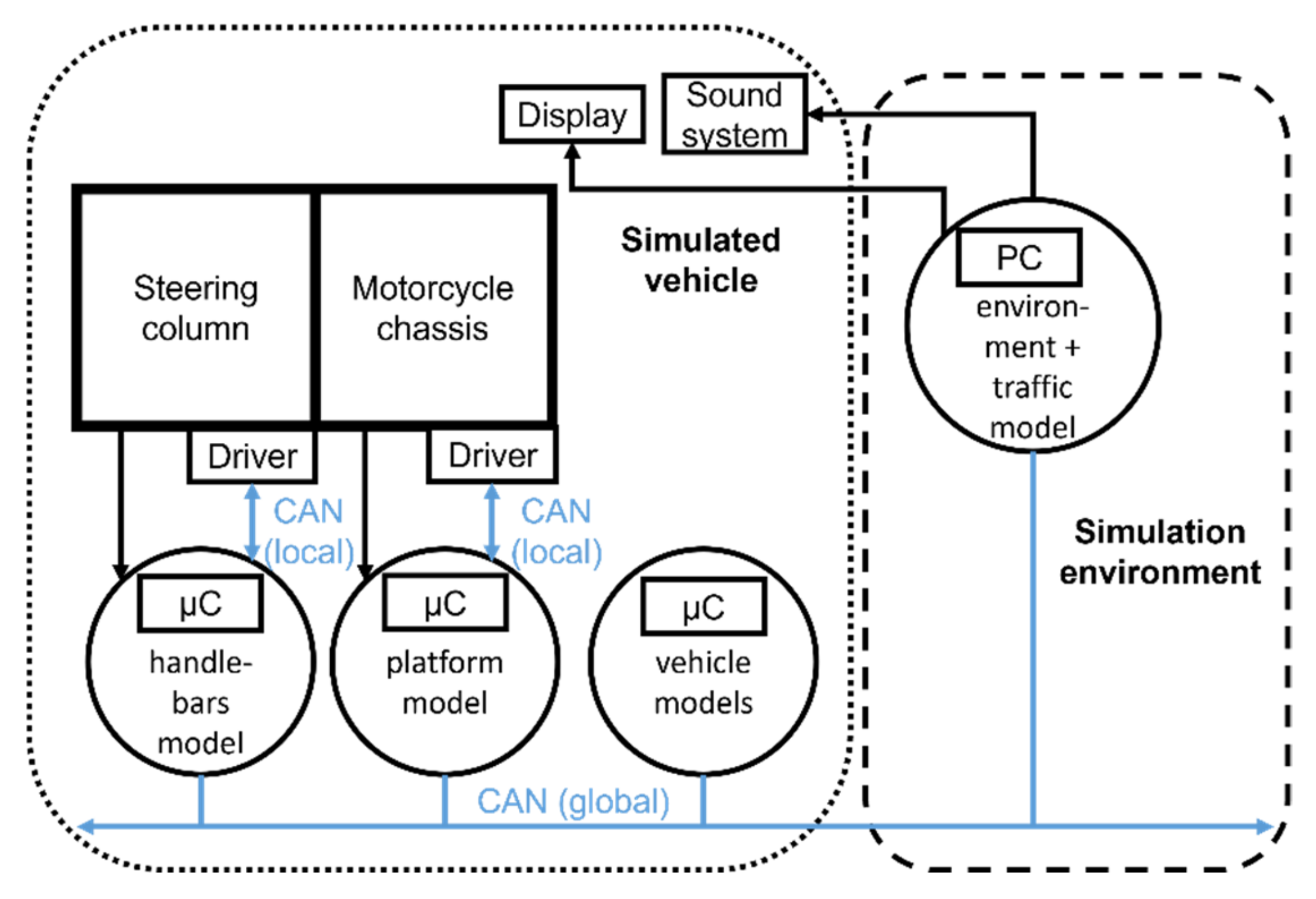
The embedded calculators exchange data with each other and with a centralized PC. The latter computes a multi-agent traffic model and renders the visual and auditory environment to the rider. The PC can also log data if needed (for experimental purposes). The hardware/software architecture is represented schematically in
Figure 8. This representation highlights that the motorcycle-riding simulator is composed of the following two parts, as previously mentioned: (1) the simulated vehicle and (2) the simulation environment.
The dedicated calculator computes two models of the motorcycle, an engine model (kinematics of the motorcycle) and a dynamic model.
Table 1 summarizes the timing of the different models computed.
4.3. Rider/Virtual Motorcycle and World Interfaces
Our simulator combines several types of sensors and actuators that can be either real or virtual. A simple movement of the rider implies a measure (by a sensor) and an inherent change in the simulator’s physics (e.g., modification of the center of gravity of the simulator). Thus, there can be several ways of combining real or virtual sensors and actuators to establish the link between the rider and the simulated motorcycle, while maintaining the acceptability of the illusion. Notably, the illusion also strongly relies on the quality of the simulated (and rendered) road environment and of the behavior of the various simulated actors (such as other vehicles and pedestrians) [
28].
The interfaces used in the motorcycle-riding simulator are classified in
Table 2, using the categories discussed in
Section 3.
The most complex interfaces are the ones that include a real sensor and a real actuator because of the inherent coupling brought into play. For this reason, moving forward, we discuss, in turn, the two dynamic bodies of our motorcycle-riding simulator and the instrumentation strategy employed for each of them.
5. Dynamic Body n°1: The Steering Column
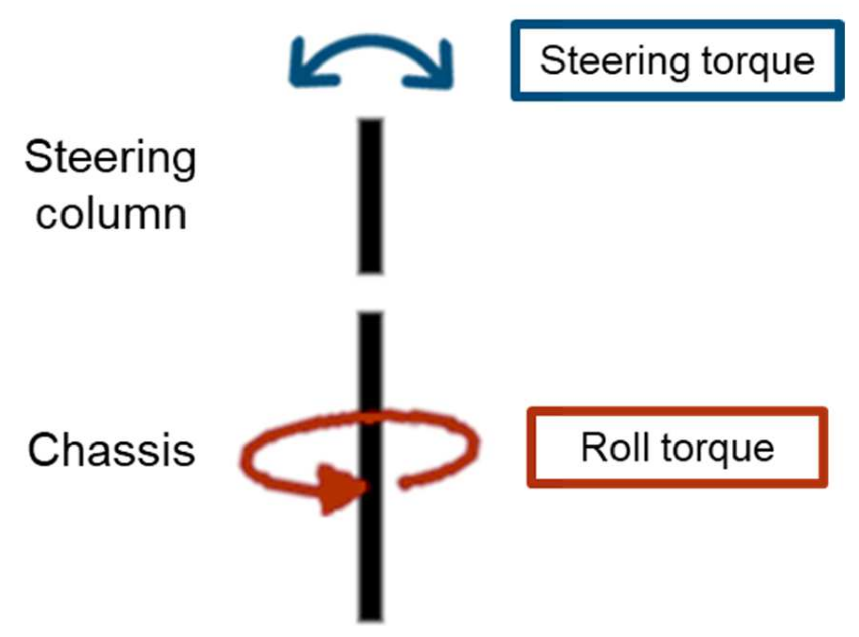
Because of the instability inherent to inverted pendulums, driving a motorcycle is a more complex task than driving a car. The rider controls the motorcycle’s trajectory through the following two torques: (1) the steering torque, i.e., the torque applied by the rider to the steering column through the handlebars; and (2) the roll torque, resulting from the rider’s body tilt or weight put on the footrests [
29]. This principle is represented schematically in
Figure 9. The two torques result in a steering and roll angle of the motorcycle. This introduces lateral and gravitational forces that are balanced by centrifugal and centripetal forces, which allow the rider to maintain their equilibrium.
5.1. The Issue of the Steering Column in Motorcycle Riding
In motorcycle riding, the steering column brings together several torques, which are as follows: (1) the torque applied by the rider on the handlebars (i.e., the steering torque); (2) the torque resulting from the gyroscopic effect of the wheel; (3) the torque resulting from tire/road contact; and finally, (4) the torque indirectly induced by the action of the rider on the roll of the motorcycle chassis. The position of the handlebars is influenced by all these torques. In our motorcycle simulator, the state of the handlebars (position, speed and acceleration) is controlled by the vehicle model. It is evident that there is significant coupling between the sensor and actuator in the particular case of the handlebars interface.
As previously mentioned, not all the physical phenomena of motorcycle riding can be physically reproduced by a simulator. For example, in our motorcycle-riding simulator, there is no wheel or road surface, which means that the torque resulting from tire/road contact must be modeled and simulated through computations.
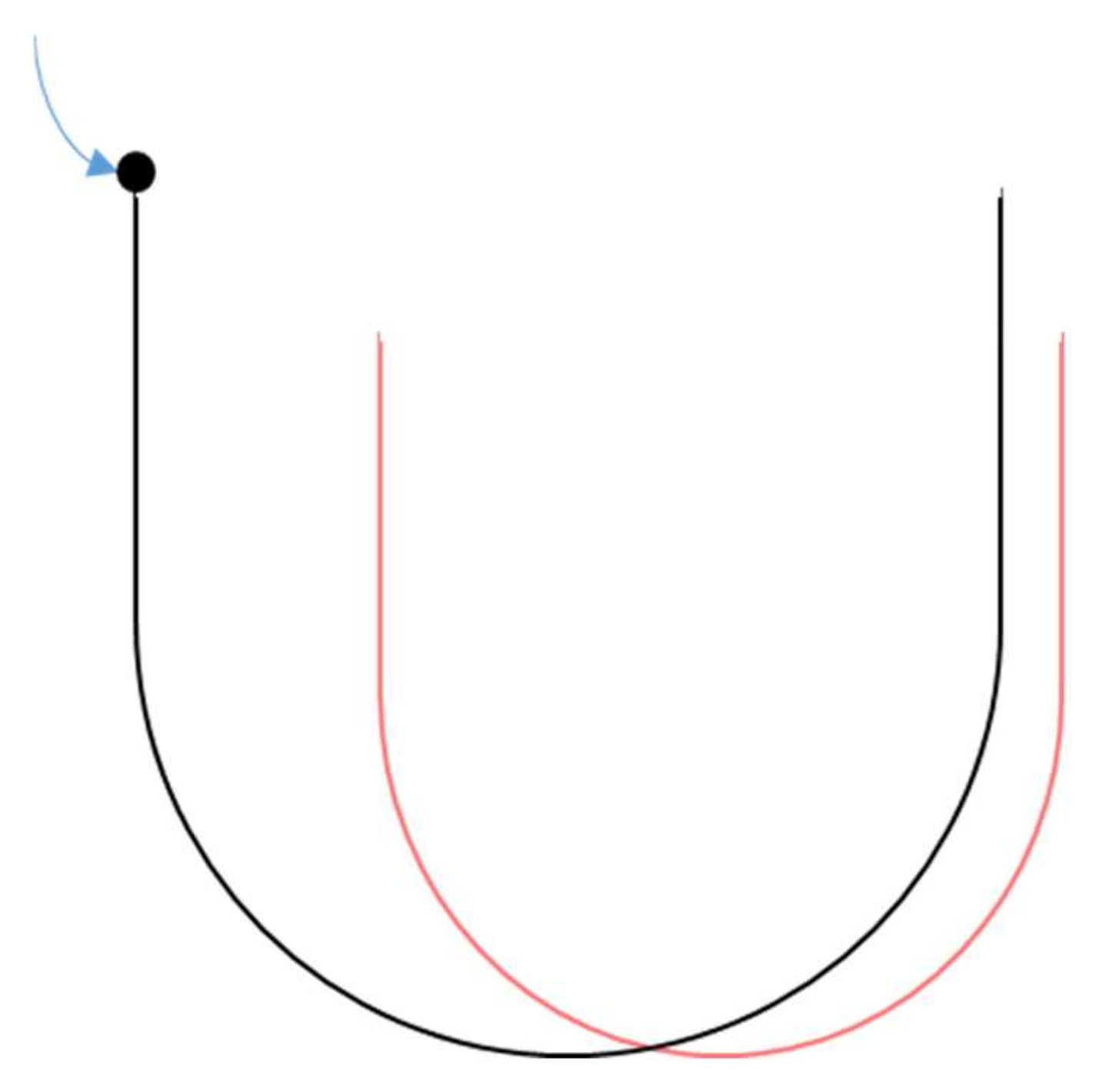
While riding, if we consider that the motorcycle is at an equilibrium point, i.e., at stable vehicle speed and angular positions (steering angle, roll, pitch and yaw), to change its trajectory, the rider can use the handlebars. This action destabilizes the motorcycle. The motorcycle is destabilized until it reaches a new equilibrium point. One can consider a figurative representation of this situation by displacing a ball in a bowl, where the equilibrium point is the bottom of the bowl. The exact shape of the bowl is defined by the riding situation at the current time. In the simulation, the bowl is different from what it would be in reality. This principle is illustrated in
Figure 10. From this, it is easy to understand that the equilibrium point of the simulated motorcycle is different from that of the real motorcycle. In some cases, the system cannot converge towards an equilibrium. In this case, the rider loses control, which poses a problem for the acceptability of the simulator.
One must note that the handlebars of a motorcycle have a dual function from the rider’s point of view; they serve both a function of control and haptic perception. The haptic sensory cues at the handlebars are essential for the rider and significantly affect their riding behavior.
In the case of car driving, the torques involved at the steering wheel are not centrally located [
30]; therefore, their measurement and control are relatively simple. In the case of motorcycle riding and for high speeds, the variations in the angular position for cornering maneuvers are of low or even very low amplitude (less than 1°). Moreover, if the speed increases, the resistive torque increases. This combination of high torque (up to 80 Nm) and low angular amplitude needs high precision to measure and control; (a) when the rider applies torque to the motorcycle handlebars, the steering column rotates and (b) producing high resistive torque with small angular motion is difficult, without inducing mechanical vibrations (due the frequency of the hardware power controller). That is why we tested and researched an actuator with minimal vibration. The servo actuators used for positioning satellite antennas on Earth are excellent candidates. Moreover, such actuators are without backlash, which is crucial for haptic feedback.
In order to operate in a closed loop, the simulator must be able to measure the torque and to use the value acquired without modifying the position of the handlebars, which is a result of the vehicle model calculation, and this must be within an acceptable time frame for the stability of the model and the haptic perception of the rider.
Based on these considerations, we can conclude that the design of a physical motorcycle steering column for a simulator is a complex problem that requires technological choices, taking into account the acceptability from the point of view of the rider in the loop.
5.2. Motorized Handlebars Design
Our motorcycle simulator’s initial handlebars motorization system (a DC motor and a pulley-belt system) was derived from a car simulator’s force feedback steering wheel. It could not guarantee closed-loop operation (i.e., it was not possible to measure the steering torque without changing the state of the handlebars). That is why we replaced it.
Table 3 summarizes the design objectives derived from the detailed considerations and the solutions we found.
These choices have their inherent drawbacks. The first one to consider is possible electromagnetic compatibility (EMC) issues (i.e., the need for electrical isolation of all sensors and sub-systems) because for the performances specified, the servo-actuator is powered with a three-phased 380 V supply (vs. a low voltage power supply in the initial system). An EMC problem can cause many dysfunctions, for example, for displays. The second issue is that the type of actuator chosen (i.e., an actuator for high-precision positioning) is not made to motorize systems with a mechanical stopper. The motorcycle handlebars are limited by a left/right mechanical stopper; the handlebars are blocked by the frame at ±35°. As the torque involved can be of high value (around 160 Nm in the case of our servo-actuator), this poses a significant risk of actuator breakage. To prevent this, we installed a mechanical torque limiter, in addition to software securities.
5.3. Steering Column Sensor/Actuator Dataflows
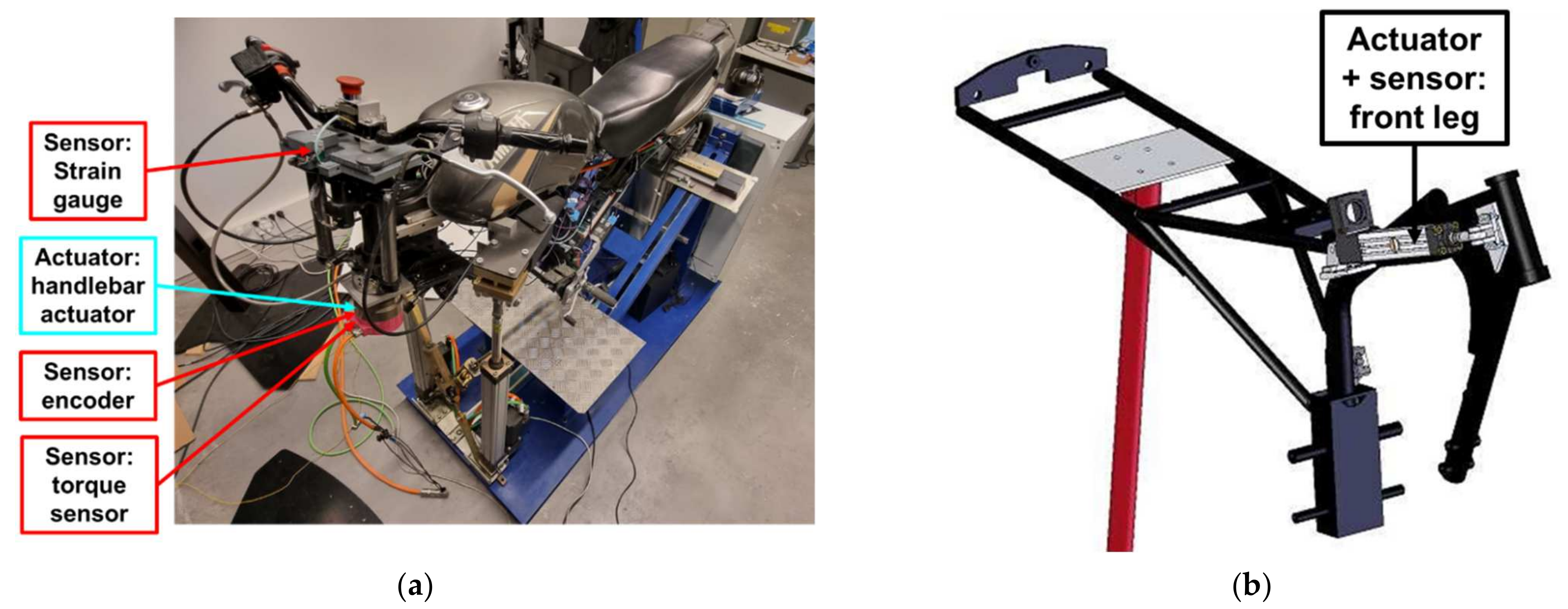
We have mentioned that the steering column sub-system (dynamic body n°1) combines the following two aspects: (1) steering angle control (the motorized handlebars) and (2) handlebars/rider distance control. For the former, the new motorization system is a servo-actuator mechanically coupled to the steering column. For the latter, a linear leg and a brushless actuator are used. The localization of the sensors and actuators of the steering column is detailed in
Figure 11. The amplitudes of all movements can be reduced/increased independently and “on the fly” using configurable gains.
The data exchanged concerning the steering column are summarized in
Table 4.
5.4. The Steering Angle DOF
If we consider the schematic representation of a real sensor/real actuator interface in
Figure 5a, the sensor/actuator interface of the steering angle DOF is characterized by the following relationships:
A and B includes the force data from the sensors (directly representing the human action in the form of steering and roll torques) and handlebar actuator position and velocity (modified by human actions);
C includes the handlebar actuator and left and right actuators of the chassis, all controlled by the vehicle model;
D includes the coupling that is necessary for the human acceptability of the simulator.
The actions of the steering and roll torques need to be combined when controlling the handlebars to create motion that is acceptable, i.e., physically and time coherent.
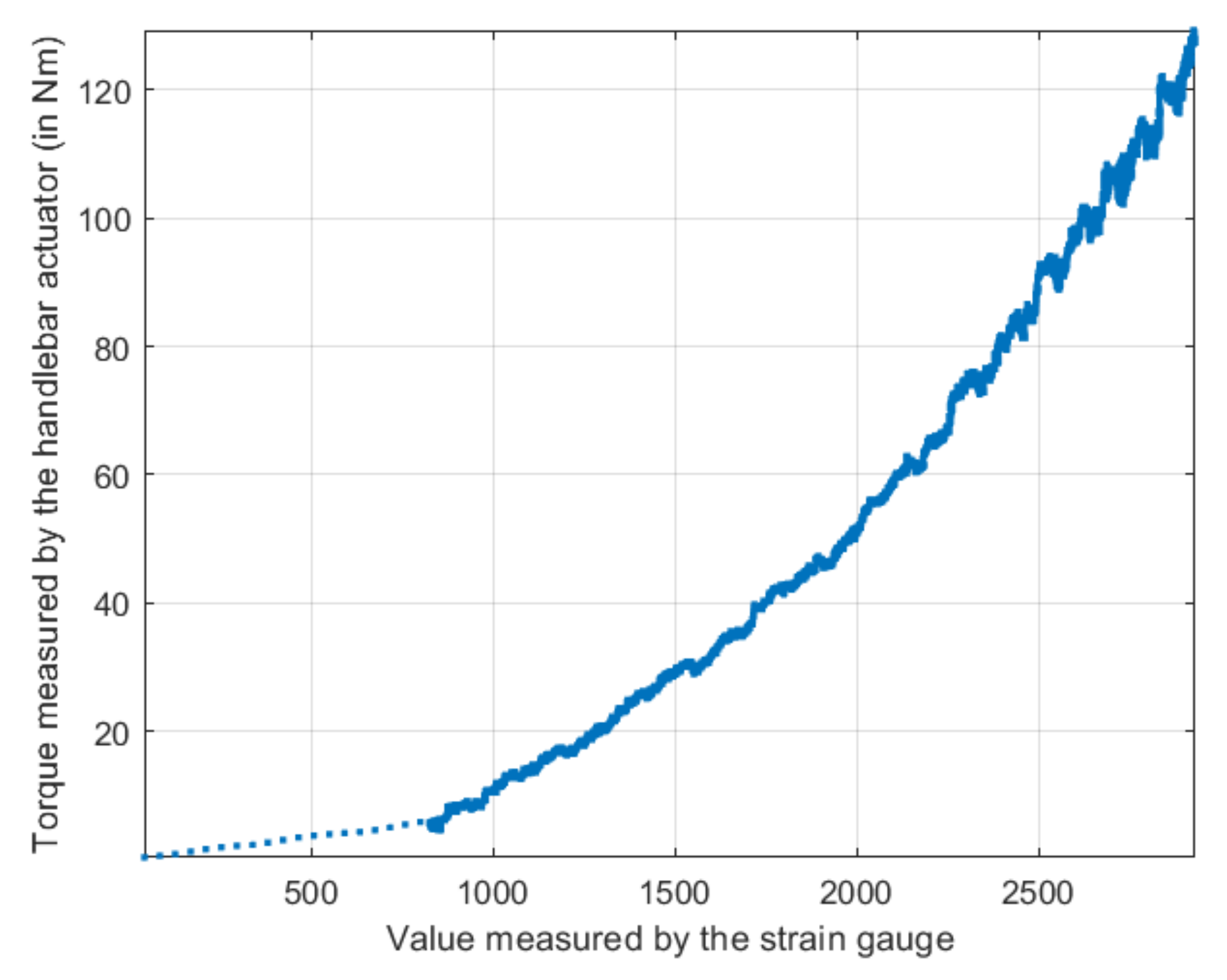
The steering torque is computed from the actuator and strain gauge data. The relationship between them was determined through a process of calibration. Since the relationship is not dependent on the rider (only on the steering column assembly), the calibration process does not need to be repeated for each rider. An example of the data used for determining the relationship between steering torque and actuator torque/strain gauge data is shown in
Figure 12.
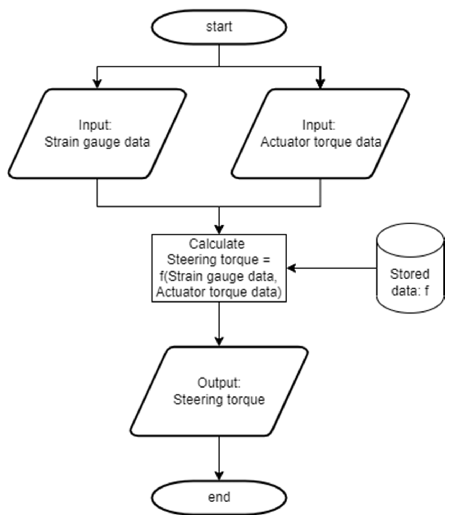
The flowchart in
Figure 13 shows the computation process of the steering torque. The computed value is used as an input of the motorcycle model.
To control the motorized handlebars, the microcontroller computing the handlebars model can communicate with the dedicated servo-controller via a local CAN bus with the CANopen protocol. However, this protocol is verbose and slow, posing a problem both for the control and for the period at which feedback data are available. We have, therefore, chosen to use a ±10 V analog input reference, rather than a reference sent over the local CAN bus, to control the servo-actuator. For the encoder data acquisition, we implemented direct decoding of the sine/cosine encoder signals by using an FPGA module (DE0-Nano) because all other protocols (EnDat 2.1/01 protocol, which uses RS 485, or local CANopen data) are too slow to guarantee real-time behavior (i.e., 200 Hz or higher for haptic perception).
5.5. Results and Discussion
Because the steering column constitutes a complicated issue (as discussed), we have conducted a primary acceptability test campaign for the new design of the motorized handlebars [
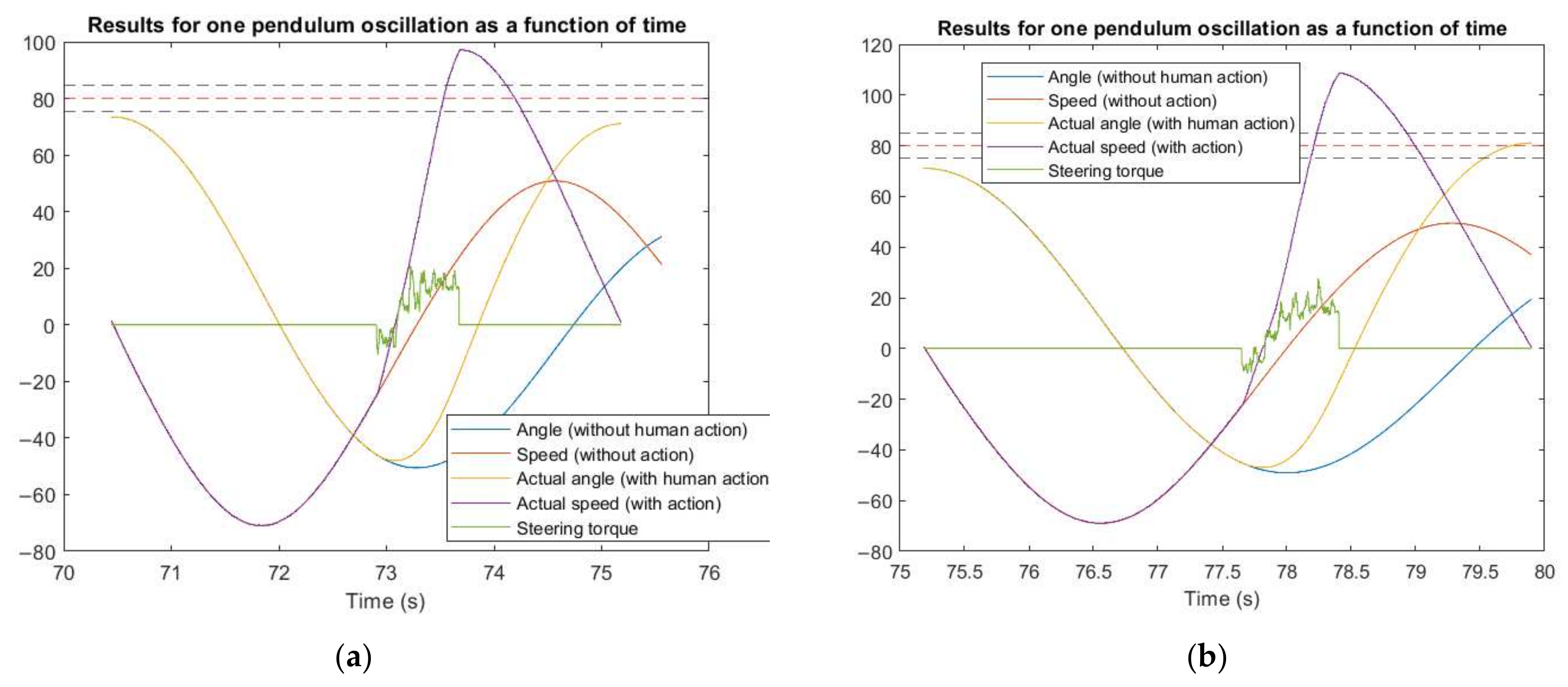
18]. This pilot experiment was conducted using our motorized handlebars POC system for rendering haptic cues and a head-mounted display (HMD) for visual feedback. The handlebars sub-system was validated using subjective measures and task performance (objective measures) in a simple control task, stabilizing a simulated pendulum’s oscillations.
Figure 14 shows an example of the results obtained during this pilot experiment regarding the computed steering torque.
Figure 15 shows an extract of the results of our pilot experiment that highlights the physical and temporal coherence of the signals and cues. It shows that the physical action of the participant is captured by the motorized handlebars system and that the system is controlled according to it. The results also support the human acceptability of the system from an objective standpoint; the participants were asked to push the pendulum so that its endpoint for the oscillation was in the zone delimited by the dotted lines. Here, the participant successfully adjusts their action from one repetition to another (
Figure 15a: pendulum not pushed far enough;
Figure 15b: pendulum reached the goal zone).
The preliminary results focused on haptic rendering on the motorcycle handlebars align with our design and instrumentation strategy; this design significantly improved the quality of the haptic cues and, therefore, the acceptability for the human operators/riders. We have, therefore, fully integrated this work into our motorcycle simulator. This integration is carried out via the global CAN bus (see
Figure 8). We then applied the same instrumentation strategy to the second dynamic body of the motorcycle simulator, the motorcycle chassis. This is what we describe in the next section.
6. Dynamic Body n°2: The Motorcycle Chassis
6.1. Chassis Sensor/Actuator Dataflows
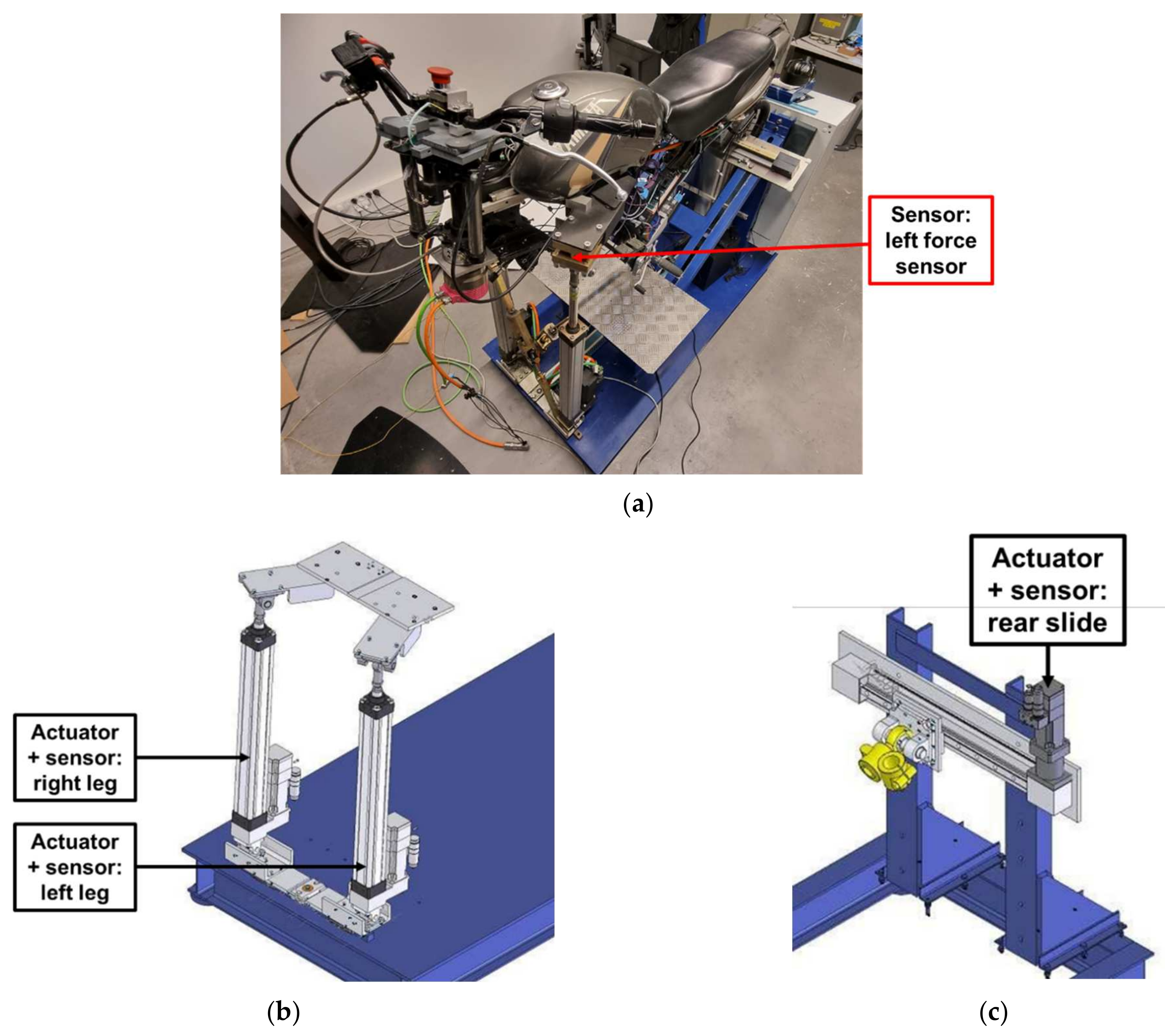
The motorcycle chassis is adapted from a real Yamaha YBR 125 cm3 and mounted on a three DOF dynamic platform, as follows:
Roll and pitch, rendered by two linear legs (at the front of the simulator) and brushless actuators;
Yaw, rendered by a slide (at the rear) and a brushless actuator.
The localization of the sensors and actuators of the motorcycle chassis is detailed in
Figure 16. As for the steering column, the amplitudes of all movements can be reduced/increased independently and “on the fly” using configurable gains.
The data exchanged concerning the motorcycle chassis are summarized in
Table 5.
6.2. The Roll DOF
The roll motion is essential for the stabilization and guidance of a motorcycle. However, in motorcycle-riding simulations, as already stated, it is impossible to render centrifugal and centripetal forces. Simulator designers use different strategies to cope with this absence, combining visual tilt and chassis roll angles [
31,
32,
33]. Depending on the architecture of their simulator, they try to establish a compromise between tilting the motorcycle with a sufficient angular speed to signal the beginning of the rolling movement, while limiting the roll angle to prevent any sensation of falling or critical imbalance.
The solution used in our simulator was to limit the chassis roll angle and add a visual roll angle [
26,
34] by tilting the image in the opposite direction of the turn, to give the rider the sensation of getting closer to the ground [
35]. The visual gains can be configured depending on the needs of the experiment.
To compute the roll torque, we used force sensors situated on the top of each of our simulator’s two front legs. These force sensors are tensile/compressive force transducers (note: only compressive force is pertinent for our case). The sensors’ positions are essential. We chose to align them on the horizontal chassis plane, which is lower than the center of gravity of the motorcycle plus the rider. This means that depending on the strategy used by the rider (either modification of their center of gravity by holding on to the tank with their legs or pushing on the footrests or a mixed action), the capture of their action may be more or less effective.
For this choice of instrumentation, the simulated motorcycle is systematically self-falling if weight compensation is missing. This is because the legs’ force sensors measure the rider’s weight; this value changes depending on the chassis roll angle. Therefore, we take into account the rider’s weight when computing the roll torque from the force sensor data. We implemented a correction of the measured force sensor values depending on the chassis tilt (roll angle).
When the rider first is in position on the motorcycle chassis at the beginning of the experiment, their weight is measured by the difference between the force sensor data for the chassis on its own and with the rider on it. Knowing this weight, we can compute the corrected force sensor data for all roll angles by using a relationship we found through a calibration process. An example of the data used for calibration is shown in
Figure 17.
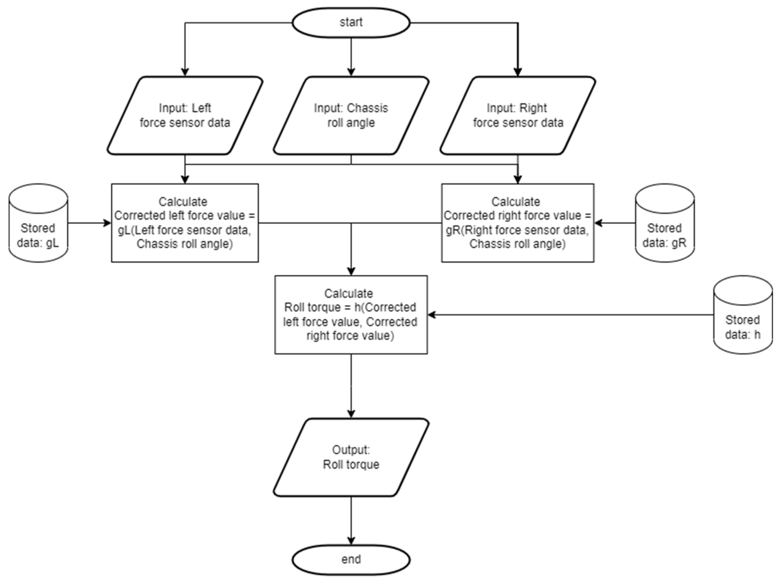
The flowchart in
Figure 18 shows the computation process of the roll torque. The computed value is used as an input of the motorcycle model.
The actions of the roll and steering torques need to be combined when controlling the platform to create a motion that is acceptable, i.e., a physically and time coherent motion.
6.3. Results and Discussion
Given the complexity of the architecture of our rider-in-the-loop motorcycle simulator, as we have tried to describe in this article, the results we have at this point essentially concern the motorized handlebars sub-system (presented above, as well as in our previous work), in addition to the preliminary results, which concern the temporal coherence of the complete system.
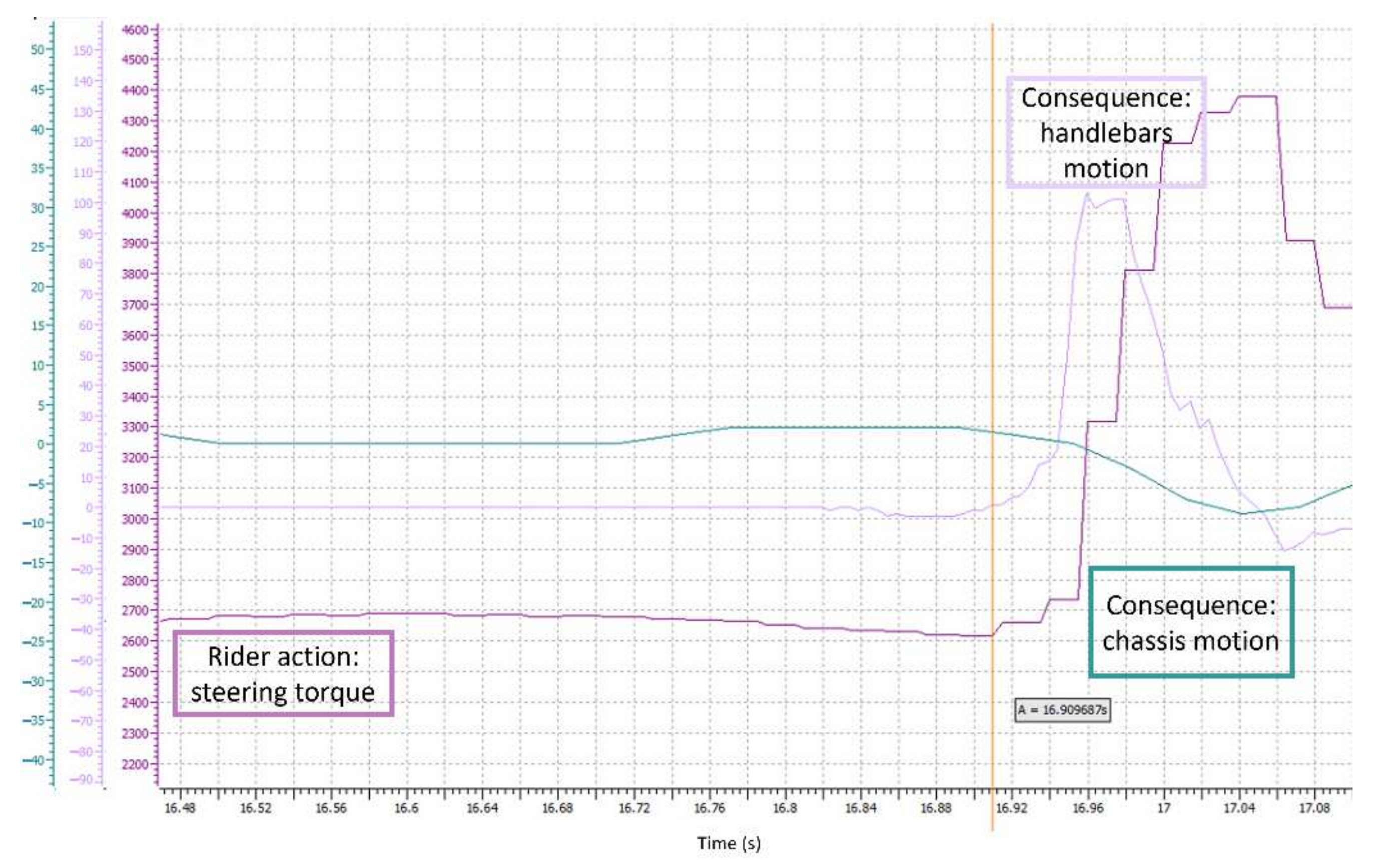
Figure 19 shows that there is an action-reaction effect between an action of the rider (in the form of an impulse in steering torque here) and the reaction of the virtual motorcycle (in the form of the resulting handlebar and chassis motion). The effect is not direct because the input stimulus passes through several models to compute the physical response, including the motorcycle dynamic model, handlebar behavior model, and chassis behavior model. The results are, therefore, complex to characterize.
In the results pictured in
Figure 19, the rider’s input stimulus, i.e., the steering torque, is initiated at 16.911 s. The measured handlebars speed (an output of the vehicle model and the handlebars model) starts to change at 16.916 s, i.e., 5 ms later. This time delay fits the design constraints for the steering column dynamic body (as described previously). The difference between the values measured by the left and the right force sensor, an image of chassis roll motion, starts to change at 16.938 s. This means that the chassis starts to be significantly tilted 27 ms after the input stimulus. This time delay is longer than the design constraints for this dynamic body, i.e., the actualization of the chassis DOFs at a period of 10 ms. However, this does not mean our expectations are not met; the roll DOF is significantly more limited in amplitude than the steering angle DOF. As a result, even if the roll angle computed by the motorcycle model starts to change after 10 ms, significant roll motion of the chassis (an output of the platform model) happens later. These preliminary results are promising.
It is still necessary to set up several experimental campaigns with both subjective and objective variables of interest. Further results that we are particularly interested in include rider acceptability of our simulator (for motorcycle riders of different backgrounds and riding experience) and its controllability. These aspects are determining factors in whether or not our simulator will fit our expectations and needs for our use in rider-centered applications and studies.
To summarize, designing a HUIL dynamic motorcycle simulator is one task but taking into account its acceptability for the rider (in the simulation loop) is another.
7. Conclusions
This article details our motorcycle-riding simulator’s design, divided into two mobile bodies, the chassis and the handlebars. In particular, we have detailed the instrumentation choices made (including optimal data frequencies) for each of these two bodies to solve the different issues raised by the motorcycle dynamics’ complexity and the complexity of building a simulation tool with a human being in the loop. Our findings have allowed us to identify design strategies for motorcycle-riding simulators and, in general, human-in-the-loop simulators, taking into account the issue of acceptability.
The motorcycle simulator as a whole works. Because the steering column constitutes a challenging issue, a primary acceptability test campaign concerning the new design of the motorized handlebars has already been conducted [
18]. A new campaign has been planned to validate the complete system. It will be conducted in partnership with colleagues in experimental psychology and involve riders from different backgrounds (such as age, riding experience, and type of motorcycle).
Furthermore, from an instrumentation point of view, we plan to implement additional corrections of sensor data depending on motorcycle speed to compensate for dynamic effects, such as the inertia of the dynamic platform, plus rider assembly. We also plan to replace the CAN (1 Mbits/s) buses with CAN FD buses (8 Mbits/s with larger data frames) to improve transmission reliability, knowing that for our application, a substantial amount of data is transmitted at a relatively high frequency.
From a “human-centered” point of view, we will soon conduct an experiment on the impact of the simulator’s architectural complexity vs. the vehicle model complexity on the feeling of presence and virtual trajectory control. One must recall that, in driving simulations, the driver does not drive a real vehicle but remotely operates a vehicle model, relying on the subset of the sensory stimuli of the real driving situation reproduced by the simulator. We hypothesize that better control of the vehicle is possible when vehicle model complexity and simulator architectural complexity (which is the limiting factor for sensory fidelity) are compatible with each other. Good control minimizes the erratic movements of the virtual vehicle, and the occurrence of simulator sickness is, thus, reduced. The design of the simulator presented here, in addition to demonstrating improved rider acceptability, is well adapted to our future studies, since many aspects are independently configurable, including vehicle model (implemented on a dedicated calculator) and behaviors of the various degrees of freedom of the motion rendering (implemented on other dedicated calculators).


