1. Introduction
Approximately 800 million people worldwide do not have access to routine medical examinations [
1]. Small urban centers often lack imaging equipment, such as CT scanners as well as clinical analysis and specialized pediatric follow-up, among others, due to their high use and maintenance costs. Bioelectrical impedance spectroscopy (BIS) has proved to be a non-expensive and robust alternative to these tests in recent years, since it has been used in applications such as identifying small carcinomas [
2], monitoring respiratory diseases in newborns [
3], and body composition analysis [
4], among others. BIS enables performing non-invasive examinations, without exposing patients to harmful radiation or toxic agents, at relatively low construction costs. Recent advances achieved in BIS imaging systems have proved the effectiveness of this methodology in pre-clinical, diagnostic and follow-up examinations [
5].
BIS often uses four electrodes placed on the investigated object (patient’s tissue). A voltage-controlled current source (VCCS) is used to stimulate the aforementioned object within a pre-set frequency spectrum. This current, which circulates through a pair of external electrodes, generates a potential drop (response to the stimulus) in another pair of internal electrodes. Voltage is measured by an instrumentation system that enables finding the impedance spectrum. Both composition and extra/intracellular constituents of biological tissues are associated with the impedance spectrum [
6]. A conductivity model would enable one to find parameters capable of featuring electrical conductivity dispersion regions associated with cell wall. It would also allow differentiating cells in a given tissue as well as assessing its health.
The voltage-controlled current sources (VCCSs) used in BIS play a fundamental role in the process of measuring and featuring different tissues. VCCSs, whose output impedance remains high (in the magnitude of M
) for at least three decades of frequency, play a crucial role in limiting the resolution of images generated in electrical bioimpedance tomography systems [
5]. The Howland current source, which is often used in this application type, presents output impedance with sensitive dependence on resistor (describe which resistor) matching as well as open loop gain variation in operational amplifiers [
7]. High-precision resistors arranged on the silicon wafer (on-chip resistors) increase the cost and limit the performance of the measurement system in integrated implementations (ASIC). However, the phase error in the vicinity of the dominant pole—associated with the output impedance—grows and affects the measurement of the imaginary component in the spectrum. It means that the operation happens at frequency range lower than the initially planned bandwidth.
On the other hand, the use of current-controlled oscillators in electrical bioimpedance spectroscopy has been poorly explored so far [
8]. Although sinusoidal and non-linear current oscillator circuits are well-known in the literature, adjustments in frequency, amplitude and oscillation conditions still fail to meet BIS’s needs when it does not use additional, complex and expensive electronic devices. Another issue lies in not knowing the phase of the generated signal, since it requires an additional system to enable synchronization with the data measurement and processing equipment. However, simple structures based on second-generation current carriers are a promising alternative to be used in BIS, since they are capable of reaching frequencies in the magnitude of a few tens of MHz and, consequently, of outperforming Howland current sources [
9].
The aim of the current study is to propose a new current oscillator topology capable of meeting BIS’s needs. This circuit combines the features of VCCS and sinusoidal oscillators. A reference sync signal input simultaneously provides phase, amplitude and oscillation condition control by eliminating any additional electronic device used to control these parameters. The synchronization signal (in voltage) can be either a sinusoidal or a square wave, which would simplify the interface with digital electronics. The circuit used in synchronous operation mode follows both the phase and the amplitude of a given external reference signal. It is also possible to operate in an autonomous (unsynchronized) manner, without a control signal, since the circuit behaves like a sinusoidal oscillator in common current.
The herein proposed circuit is based on both current carriers and operational transconductance amplifiers (OTAs). All resistors and capacitors are earthed to enable their integrated implementation in a chip. Only two DC voltage signals are necessary for control and operation purposes: one for frequency control and another for synchronization. The output is formed by one current carrier and one OTA. This configuration enables two operating modes (i.e., with or without feedback), and it enables the excitation electrode’s versatility to have, or not, direct reference to the grounding one. Unlike the solution proposed by [
8], the oscillator operation in the current study was absolutely analog, since it dismissed any internal digital-to-analog converters, analog filters and additional feedback structures. The oscillator can also be easily implemented on a bench, based on using off-the-shelf components, in order to rule out the need of previous integration in wafer.
This work presents a mathematical description of the oscillator’s operation by taking into account its dynamic model. The technique is proposed by Pyragas [
10] to control and suppress chaos in non-linear systems, which was adapted to the harmonic model by using simple harmonic oscillator equations. A circuit implementation is proposed, and then PSPICE simulations are conducted using ideal components for checking its functionality.
2. Mathematical Framework
Simple harmonic oscillator dynamic equations can describe the behavior of all analog electronic sinusoidal oscillators. Thus, the behavior can be approached by the harmonic model, even in non-linear systems, when producing pure sinusoidal oscillations [
11]. Harmonic oscillations can be written in two (equivalent) forms, namely: Equation (
1) and the set of Equation (
2). The second form is mostly used for circuit analysis. Coefficients
b and
determine oscillation condition and frequency, respectively. In practical terms, initial conditions
and
are defined by the initial charge applied in analog form on capacitors. The solution could be obtained by integrating Equations (
1) and (
2).
The overall solution of Equation (
1) is:
where
Equations (
3)–(
5) shows that oscillation amplitude and phase are determined by initial conditions
and
. Phase must be known based on reference to the initial time
, when the oscillator circuit starts its dynamics. However, determining the initial conditions of the circuit in an accurate manner means defining the initial charge applied on integrated capacitors. In practice, it is very hard to be completed if high accuracy is required. Thus, oscillator circuits use damping parameter
b to trigger oscillations by momentarily placing the system in the divergence region of Equation (
1). Subsequently, the damping parameter is readjusted, after the required amplitude
A is reached, to enable obtaining stable oscillations. According to the classic implementation of the Wien bridge oscillator, a conforming amplifier, or an automatic gain control system, is used to guarantee oscillation stability by adjusting damping parameter
b based on the oscillation amplitude.
Controlling oscillation phase and amplitude is of paramount importance for BIS. Although it is possible to implement a complex system to force the initial conditions, a simplified approach based on changes carried out in Equation (
2) was then here suggested. In order to do so, the linear forcing idealized by Pyragas, which is a method often used to control chaos in non-linear systems, was included in Equation (
2) [
12]. The operating principle is quite simple; the F term in Equation (
6) continuously forces the oscillations until it reaches equality to an external reference signal in the form of
. The F term vanishes when the system oscillates according to the external reference—the aforementioned equations are summarized in Equation (
2), where
is the Pyragas’ factor,
k is the forcing magnitude and
is the external reference signal. Thus, this forcing process makes small corrections in oscillations whenever the dynamics diverges from the external reference.
The parameter
k plays a critical role in controlling chaotic and non-linear systems. However, given the linearity of Equation (
1), the following simulations show flexibility in the selection of this parameter. Unfortunately, the arbitrariness of reference signal
makes Equation (
6) non-analytically integrable; thus, their solution must be based on numerical methods.
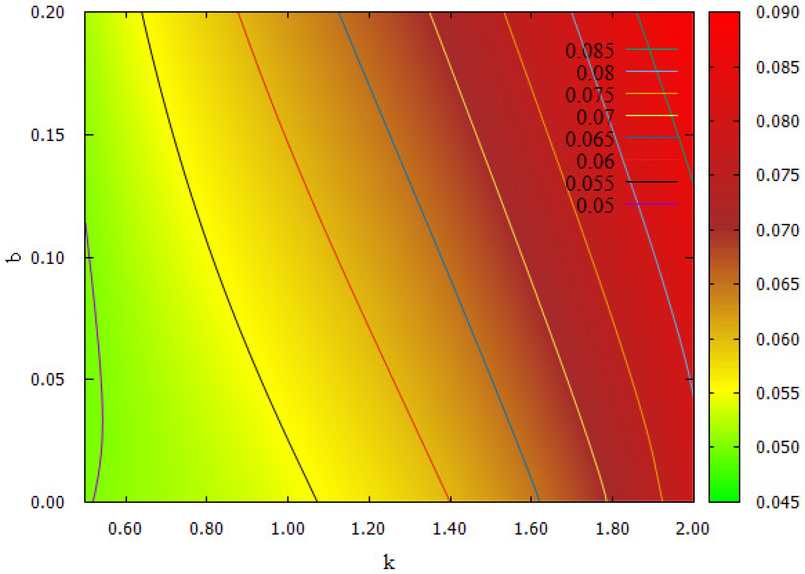
Figure 1 outlines the influence of parameter
k on the numerical solution of Equation (
6), wherein the fourth-order Runge–Kutta finite element method was used. The graph shows variation in synchronization force
actuation rate in comparison to dissipation parameter
b and to forcing amplitude
k. It is clear that the Pyragas’ factor can guarantee oscillations in the system, even for
, just by adjusting the
k value in order to reduce control actuation.
The Pyragas’ factor is approximately zero when oscillations reach a steady state; this factor makes the oscillation follow the external reference signal . In practical terms, parameter b is associated with the oscillation condition; therefore, the effective control actuation in the system does not require adjustments in the oscillation condition.
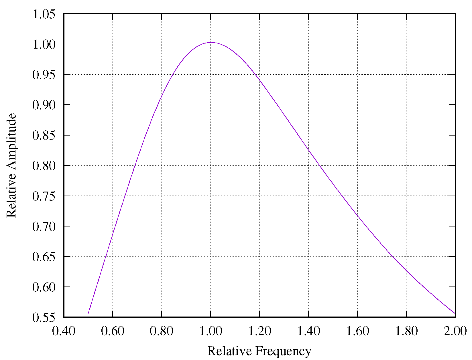
The external reference signal must have the same natural frequency of the system
during synchronized operations. When it happens, the oscillator’s phase and amplitude are synchronized with the external reference signal. The Pyragas’ factor, outside the resonance region between the forcing and the system, requires increasing the control actuation amplitude in order to stabilize the oscillations. Once the
k value is fixed, forcing a reference signal with a frequency different from
implies attenuating the amplitude in comparison to
as the difference increases, as shown in
Figure 2. This phenomenon is particularly useful in BIS, since it enables using non-sinusoidal signals, such as square wave, as reference. In this case, the oscillator works as a resonator filter by extracting the fundamental frequency from the control signal and by attenuating the other harmonic components. This feature enables the interface with logic circuits.
3. Electrical Implementation of the Oscillator
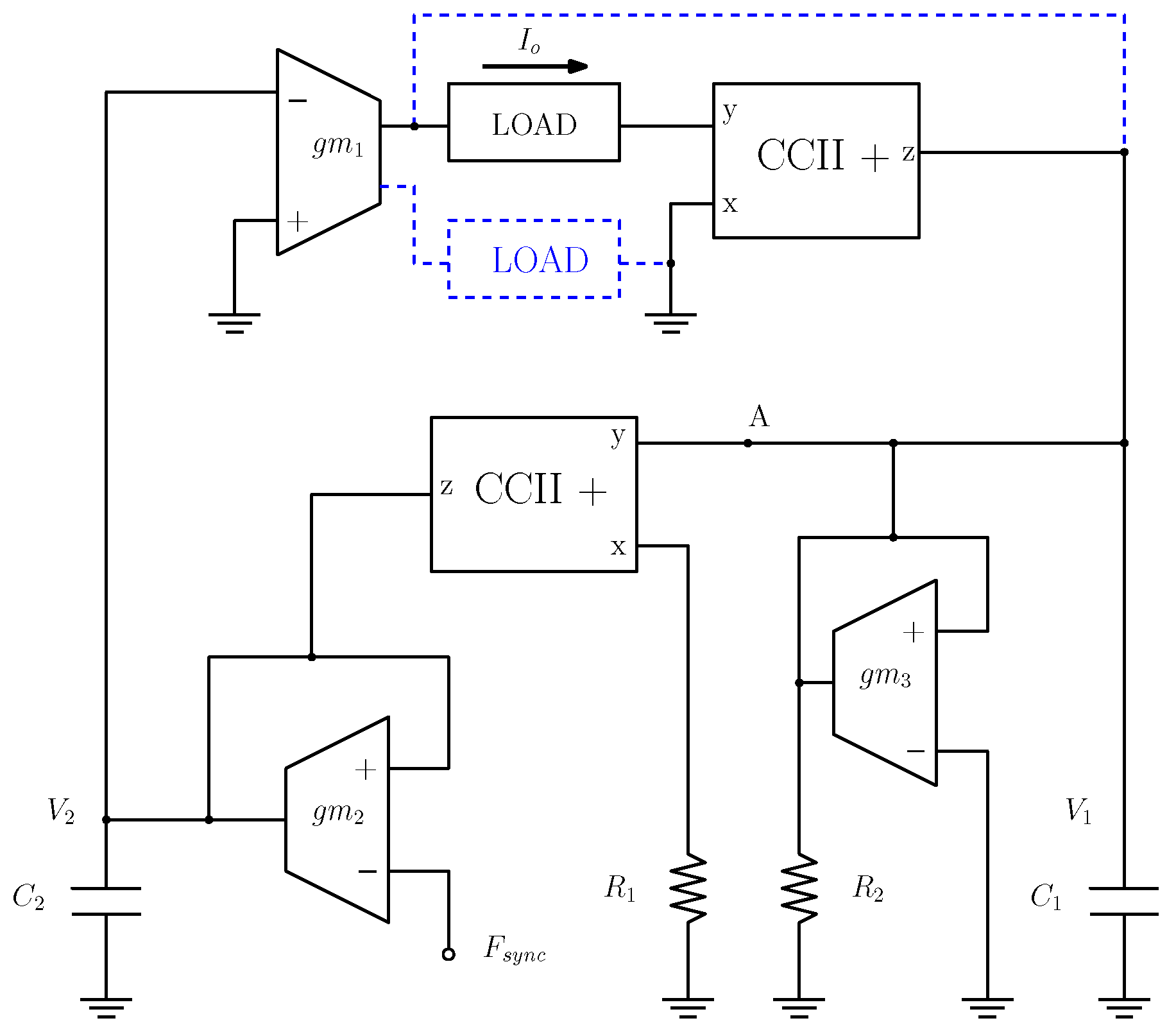
The oscillator described by Equation (
6) is shown in
Figure 3. Current carriers, along with capacitors
and
, form analog integrators for variables x and y, respectively. The operational transconductance amplifier
accounts for the Pyragas’ factor, and the synchronization signal is applied to its inverting input. On the other hand,
output must be disconnected from the circuit in desynchronized operations, where the circuit behaves like a common oscillator. Resistors
and
control the oscillation frequency and condition, respectively. The charge can be connected in two different ways: in a closed loop structure (feedback) or in an open loop structure (blue dotted line in
Figure 3). The open loop structure dismisses one of the current carriers and enables direct reference to ground. The current output, which is seen as a VCCS whose input is
, is scaled by transconductance
.
By naming the voltages on capacitors
and
as
and
, the routine loop analysis shows that:
In order to compare these equations to Equation (
6), it is necessary to dimensionlessize Equation (
7). Therefore, one finds:
By replacing Equation (
8) in (
7) and by comparing it to (
6):
Pyragas’ factor imposes
whenever the
signal has the same frequency as
during synchronized operations. This voltage appears at the inverting input of transconductor with
. Therefore, the output current is:
Equation (
10) indicates that the circuit behaves like a VCCS during synchronized operations. However, it is worth emphasizing that the output is sinusoidal regardless of whether
is formed by different harmonic components, as indicated by the system’s response to frequency mismatch (
Figure 2). The natural oscillation frequency is adjusted by resistor
, which can be replaced by an additional element of transconductance, a digital potentiometer, or an analog multiplier placed at the high impedance input of the current carrier, and it enables the control of the frequency of oscillations with a DC voltage signal. The Pyragas’ factor dismisses the oscillation condition control, which makes it possible to remove
and
from the circuit. However, whenever desynchronized operation is required,
or
can be adjusted so that factor
b in Equation (
8) equals zero after oscillations reach a steady state.
The output impedance of the oscillator does not only depend on the transconductance
. Whenever the operation takes place in feedback mode, the charge current runs through the control loop and, then, it is adjusted by the Pyragas’ factor. Based on
Figure 2, when the operation takes place in resonance mode and disregards the non-idealities of transconductor
, the output current remains fixed to the external reference, since the control mediated by
maintains oscillations’ amplitude and phase. It means that from the VCCS perspective, amplitude undergoes less attenuation as it becomes closer to the resonance condition and vice versa. Therefore, unlike the Howland current source, the output impedance has a narrow peak over the natural oscillation frequency; it moves as this frequency changes. Secondary harmonics are quickly attenuated, and it means maximum impedance over the signal of interest; furthermore, it rules out the need of using additional impedance filters and converters to ensure current output stability.
Given the resonant feature of output impedance, it is worth investigating the oscillation frequency stability after the Pyragas’ factor is introduced. Whenever the control destabilizes the oscillations, the resonance condition is not met and the output impedance decreases. Moreover, the Pyragas’ factor does not change frequency stability at high- and low-frequency thresholds.
Figure 3 shows the transfer function by breaking the loop at point A:
wherein
. Frequency stability is defined by [
13]:
wherein
and
is the transfer function phase
. The stability calculation process is based on an intricate algebraic equation that is not easily interpreted. However, it is possible to show that:
In other words, stability at high frequencies is not affected by the Pyragas’ factor. As for low frequencies, it is also possible to show that
does not depend on the Pyragas’ factor if:
Whenever the control acts in the oscillator,
therefore, condition (
14) is met as long as there is signal synchronization.
Figure 4 presents results of the transient simulation of the oscillator shown in
Figure 3. Simulations took place in a PSPICE environment, and they took into account the ideal case of all components. The circuit was initially set to oscillate under pre-defined initial conditions in order to obtain different oscillation amplitudes and phases, as predicted through Equation (
4). The damping parameter was null, i.e.,
. The
reference signal was connected to a sinusoidal voltage source at frequency of 1 MHz and amplitude of
. The
signal was multiplied by the transconductance of
m A/V, and this value was used as a reference line (purple color) in the graph shown in
Figure 4. Once the oscillations started, and after a
s transient was in place, a switch was used to connect the
output to the circuit at
s. After a transient of
s, the oscillator output current synchronized the oscillations’ phase and amplitude with
, regardless of their magnitude before the control signal acted in the circuit at
s.
Figure 5 shows the phase synchronization process based on the external reference. The circuit was set to oscillate without actuating the forcing factor. The phase amplitude and difference (in comparison to the external reference signal) were determined by initial voltages at
and
. The forcing factor was connected to the circuit at
s in order to force the phase difference into zero. The phase synchronization process speed directly depends on forcing magnitude k and on the initial phase difference in the oscillator.
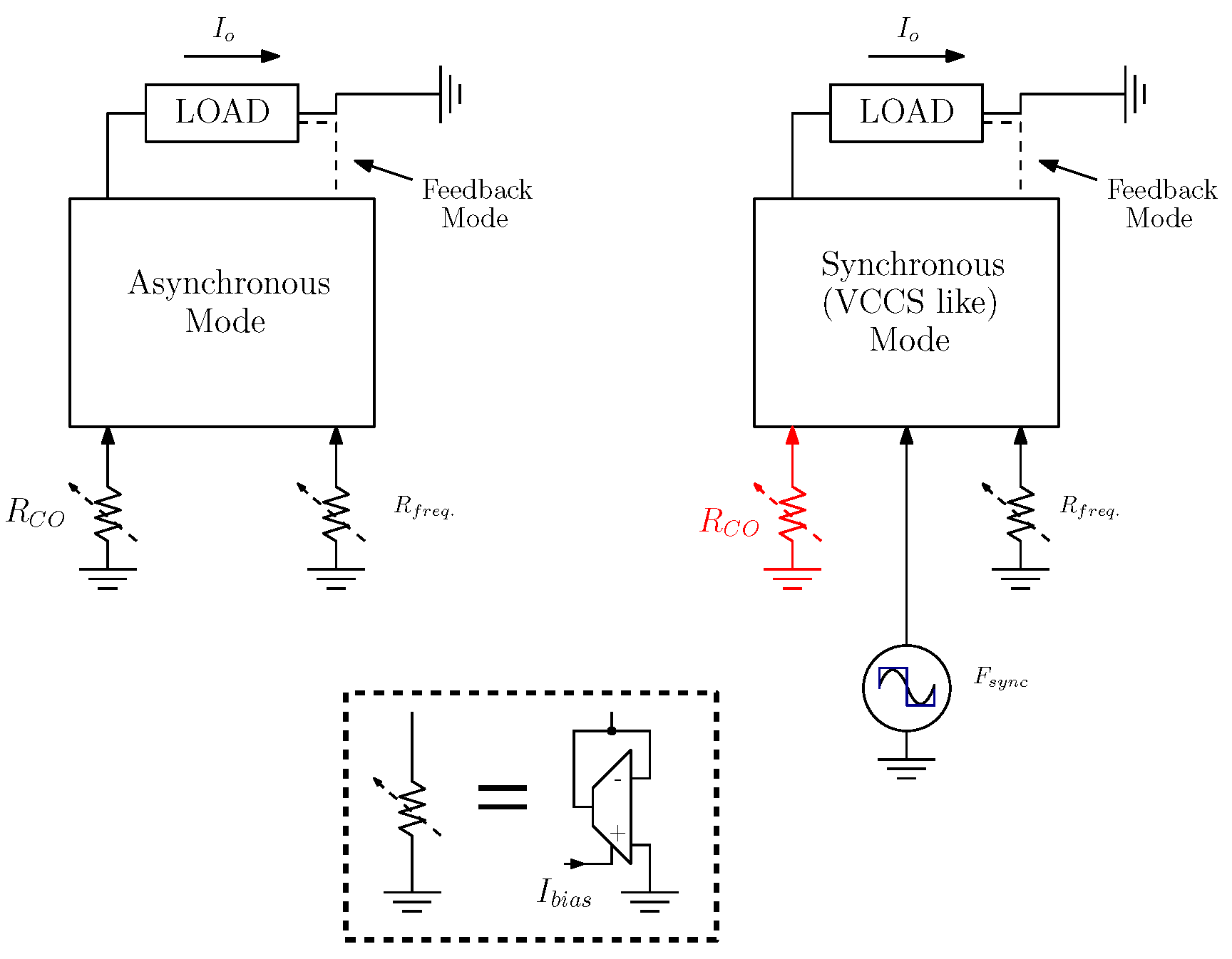
The oscillator has two possible operating modes (
Figure 6) depending on the output current and on its applications. A mirrored output transconductor, which corresponds to the blue dotted line in
Figure 3, enables the direct connection of the charge to the ground and rules out the buffer formed by the current carrier. This approach reduces the likelihood of having common-mode voltage due to unbalance across the electrodes without the need of adopting additional compensation loops. However, the output impedance becomes directly dependent on transconductor
, since the rest of the circuit behaves like a voltage oscillator and produces a sinusoidal
. The direct connection to the ground also helps reducing electrodes’ capacitance [
6]. When the operation takes place in feedback mode, the output current is susceptible to corrections performed by the Pyragas’ factor, and it increases output impedance under resonance condition. However, real current carriers present voltage offset in inputs
x and
y, and it can lead to common mode voltage errors as well as to electrode capacitance increase due to electrolytic polarization. In the last case, and depending on the offset magnitude, decoupling capacitors at the output electrodes must be used.
The initial condition control can be suppressed during the synchronized operation (right side of
Figure 6), and it means removing
and
. The Pyragas’ factor adjusts eventual deviations caused by components’ non-idealities that imply
. The desynchronized operation is featured by a lack of synchronization signal and by the disconnection of the
output from the circuit. In this case, controlling the oscillation condition is of paramount importance, since small deviations implying
prevent oscillations from starting or from being quickly damped. Therefore, in this case, the output current amplitude is not given by Equation (
10) but by the signal forming a point over parameter
, which is often seen in typical sinusoidal oscillator designs [
14]. Although this operation type is possible, it is not interesting in BIS because it requires phase synchronization system, as well as additional control over oscillation amplitude and condition, and it takes away the advantages of including the Pyragas’ factor in the system.
4. Discussions and Conclusions
The proposed current oscillator presents features specifically aimed at BIS applications. Since it enables synchronizing both phase and amplitude with an external voltage signal, it does not require additional electronic devices to control and synchronize current output, which is a fact that solves the problem associated with using oscillators in BIS. According to numerical simulations, the source’s output impedance is associated with natural oscillation frequency; this feature differs from that of VCCS, wherein oscillation frequency is often associated with the source’s output poles. The oscillator presents maximum output impedance over the natural oscillation frequency, and it attenuates out-of-interest signals during sample excitation in the system. Attenuating unwanted signals in VCCS-based systems requires using additional filters and converters.
A full model of a VCCS Howland current source using discrete components demands a precise project of the components, which takes time for designing and simulations. The main target here was to propose a model for a current oscillator based on the Pyragas technique. The Pyragas factor acts as a dynamic forcing, whose magnitude is proportional to the deviation (phase and amplitude) in comparison to an external reference signal (). Therefore, unlike the Howland source, when the output impedance decreases as increasing frequency of the input signal, the output current is forced to keep in synchronism with the reference signal. It is worth remembering that the Howland topologies operate in a different manner in comparison to this proposal which, in turn, is a current oscillator based on the Pyragas model for exciting biological tissues. On the other hand, the Howland source is a linear current source that acts as a transconductor circuit from an external voltage signal.
In the practical application process, the damping parameter
b of the proposed oscillator can be used to adjust the conditions of free oscillations, according to Equation (
6). In practice, deviations and non-idealities of the components (mainly the transconductors) might contribute with additional terms as a function of
, which can stop the oscillations. Nonetheless, the dampling parameter
b can be adjusted to compensate for these additional effects. When the circuit is forced by the Pyragas factor, adjusting
b helps to decrease the magnitude of the forced oscillation according to equations.
The proposed circuit has flexible application among different operating modes with and without feedback. It has simple electronics, and its implementation might occupy a small area inside the silicon wafer. SPICE simulations were focused on the ideal case, and they have confirmed the control actuation based on numerical simulations of dynamic equations. The Pyragas’ factor does not change oscillation stability at high and low frequency thresholds; otherwise, it would imply reducing the output impedance of the whole circuit.
The fact that all resistors and capacitors are directly connected to the ground wire makes it easy to implement this circuit in SOIC. The oscillation control interface with logic circuits can be mediated by a square wave signal that rules out the need for additional signal conditioning. A future work is under development in order to compare the bioimpedance practical results of both the Howland source and the proposed current oscillator.


