Article

A Novel MPPT Algorithm for Photovoltaic Systems Based on Improved Sliding Mode Control

Department of Electronic and Information Engineering, Liaoning University of Technology, Jinzhou 121001, China
*
Author to whom correspondence should be addressed.
Electronics 2022, 11(15), 2421; https://doi.org/10.3390/electronics11152421
Submission received: 4 July 2022 / Revised: 29 July 2022 / Accepted: 29 July 2022 / Published: 3 August 2022
(This article belongs to the Section Power Electronics)

Abstract

:
Due to the poor tracking performance and significant chattering of traditional sliding mode control in the maximum power point tracking (MPPT) algorithm, a novel MPPT algorithm based on sliding mode control for photovoltaic systems is proposed in this paper. The sliding mode control structure and new sliding mode surface of the multi-power reaching law are designed with the boost converter as the carrier of the photovoltaic system, and the sigmoid function is proposed to replace the symbolic function and saturation function in the power reaching law to improve the reaching rate and control quality of the traditional sliding mode control. Furthermore, the Liapunov function is employed to analyze the accessibility, existence and stability of the improved sliding mode control. Simulation results under dynamic and partial shading conditions show that compared with exponential sliding mode and constant speed sliding mode, the improved sliding mode control strategy can quickly track the maximum power point of photovoltaic systems under various atmospheric conditions. The proposed MPPT algorithm has stronger robustness and universality. Additionally, the efficiency of the proposed algorithm is improved by 2.3% and 5.6% as compared to the exponential sliding model control algorithm and constant velocity sliding model control algorithm. In addition, the experimental platform is constructed to further validate the feasibility and effectiveness of the proposed algorithm.

1. Introduction

Considering the aggravation of the global greenhouse effect and ecological environment deterioration, the exploitation and utilization of renewable energies have become a research hotspots in recent years. As the primary form of solar energy, PV power generation has the characteristics of easy installation, non-pollution and no noise [1]. Moreover, the complexity is effectively reduced compared to other renewable energy resources. Renewable energy has been vigorously promoted in various countries in recent years. Photovoltaic (PV) arrays, as the core of PV system, have the shortcomings of intermittency and random discreteness, and the maximum power point (MPP) of PV array drifts with the meteorological factors, mainly irradiance (G) levels and ambient temperature (T) [2,3]. Since the MPPT algorithm can quickly track the MPP without any prior knowledge, it is imminent to present an efficient and pithy MPPT algorithm with fewer maintenance costs to detect the running states of the PV system [4].
Currently, MPPT algorithms in PV systems include the perturbation and observation method (P&O), incremental conductance method (INC), self-adaptive control, artificial neural networks (ANN), meta-heuristic algorithms, the sliding model control (SMC) method, statistical method and non-linear control theory [5,6], where the SMC method has the characteristics of compact structure, discontinuous switching, strong anti-perturbation ability and good universality for time-varying nonlinear systems [7]. However, the conventional SMC strategy easily motivates the unmodeled characteristics of the PV system, which affects the reliability and robustness of SMC and leads to power chattering of PV systems.
To handle the drawbacks in conventional the SMC method mentioned above, a piecewise regulation strategy in different stages of the reaching process is constructed by using the rapidity of the power reaching law and linear feedback in the boundary layer of the saturation function (Sat) in the literature [8]. The authors of [9] developed a multi- dimensional super-spiral SMC algorithm to map the norm space of the boost converter to the state space for implementing MPPT. In [10], the P-V characteristic curve is divided into stable and tracking regions, and the P&O and SMC algorithm are employed to track MPP. The authors of [11] introduced an efficient online fractional open-circuit voltage (FOCV) MPPT algorithm based on SMC, in which the PV cell voltage, current and ambient temperature are employed to determine the open-circuit voltage for implementing MPPT. In [12], the variable-step size of P&O MPPT and SMC are adjusted by the θ-modified krill herd (θ-MKH) algorithm to improve the tracking characteristic in both the transient and steady-state. The authors of [13] developed a nonlinear backstepping terminal SMC for maximum power extraction. In [14], a ANN and backstepping-SMC (ANN-BSMC) algorithm is presented. The first one can predict the MPP voltage according to irradiance level and ambient temperature, and the BSMC is employed to adjust the duty cycle of the DC–DC boost converter. However, the reaching rate and stabilization accuracy of the SMC algorithms cited above are lower.
In order to improve the reaching rate and tracking characteristic of the conventional SMC algorithm, a novel MPPT algorithm based on SMC for PV system in this paper. Based on the PV power system with boost converter, an SMC strategy with the multi-power reaching law and new sliding surface are designed, while sigmoid is used instead of the symbolic function and saturation function to improve the control quality of the traditional SMC. Under dynamic and partial shading conditions (PSC), the feasibility and superiority of the proposed MPPT algorithm are verified by Matlab/Simulink and experimental platforms. This paper makes the following contributions: (1) A novel sliding surface S(k) is constructed; (2) an SMC structure with multi-power reaching law is designed, and the symbolic function is replaced by the sigmoid function; (3) the control quality, tracking performance and efficiency of improved SMC, exponential SMC and constant velocity SMC algorithms are compared and analyzed in detail. (4) an experimental platform is constructed to illustrate the superiority and feasibility of the proposed MPPT algorithm.
This paper is organized as follows. The control principle of PV systems and mathematical model of PV arrays are introduced in Section 2. An improved SMC for PV MPPT algorithms is presented in Section 3. Simulation results and discussion are given in Section 4. Experimental results are illustrated in Section 5. Finally, the conclusion and future works are presented in Section 6.

2. Control Principle of PV System

The PV system is mainly composed of a PV array, DC–DC converter and MPPT algorithm [15]. The PV system structure is shown in Figure 1.
As shown in Figure 1, G represents the irradiance; T is the temperature; Vpv is the PV array voltage; Ipv is the PV array current; Io is the output current; Vo is the output voltage; D is the duty cycle. Actually, the MPPT algorithm operates periodically perturbing the characteristic variables by increasing or decreasing parameters with a small amount until MPP is reached. To fulfill MPPT, the switch value with duty cycle (D) is acquired by comparing the modulated quantity with the high-frequency signal carrier [16]. In addition, the on–off time of switch cube Q is adjusted by PWM technology. To maximize the efficiency of PV system, it is necessary to match the internal and external impedances, i.e., Rpv = RL/n2 = RL(1 − D)2.

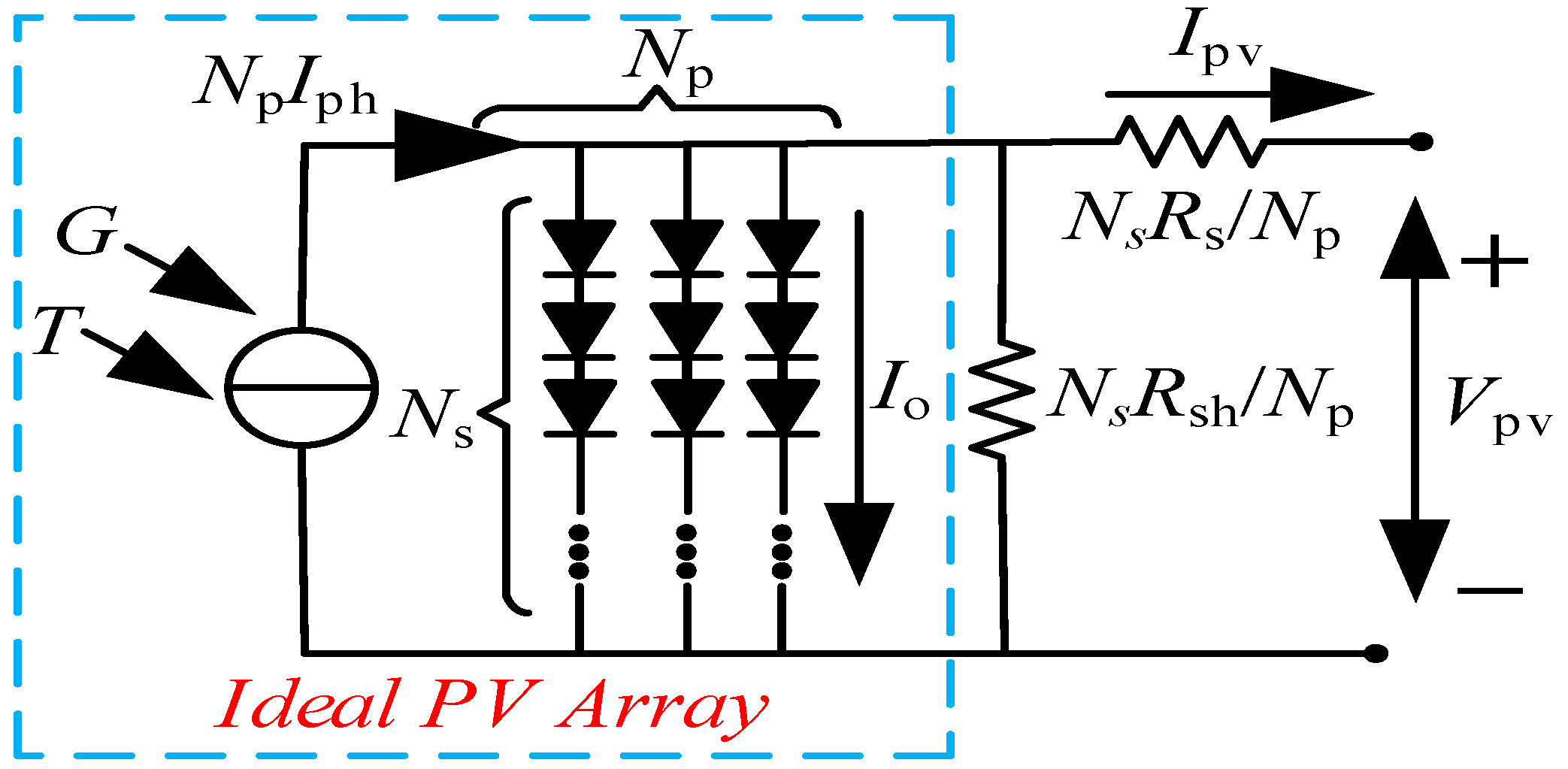
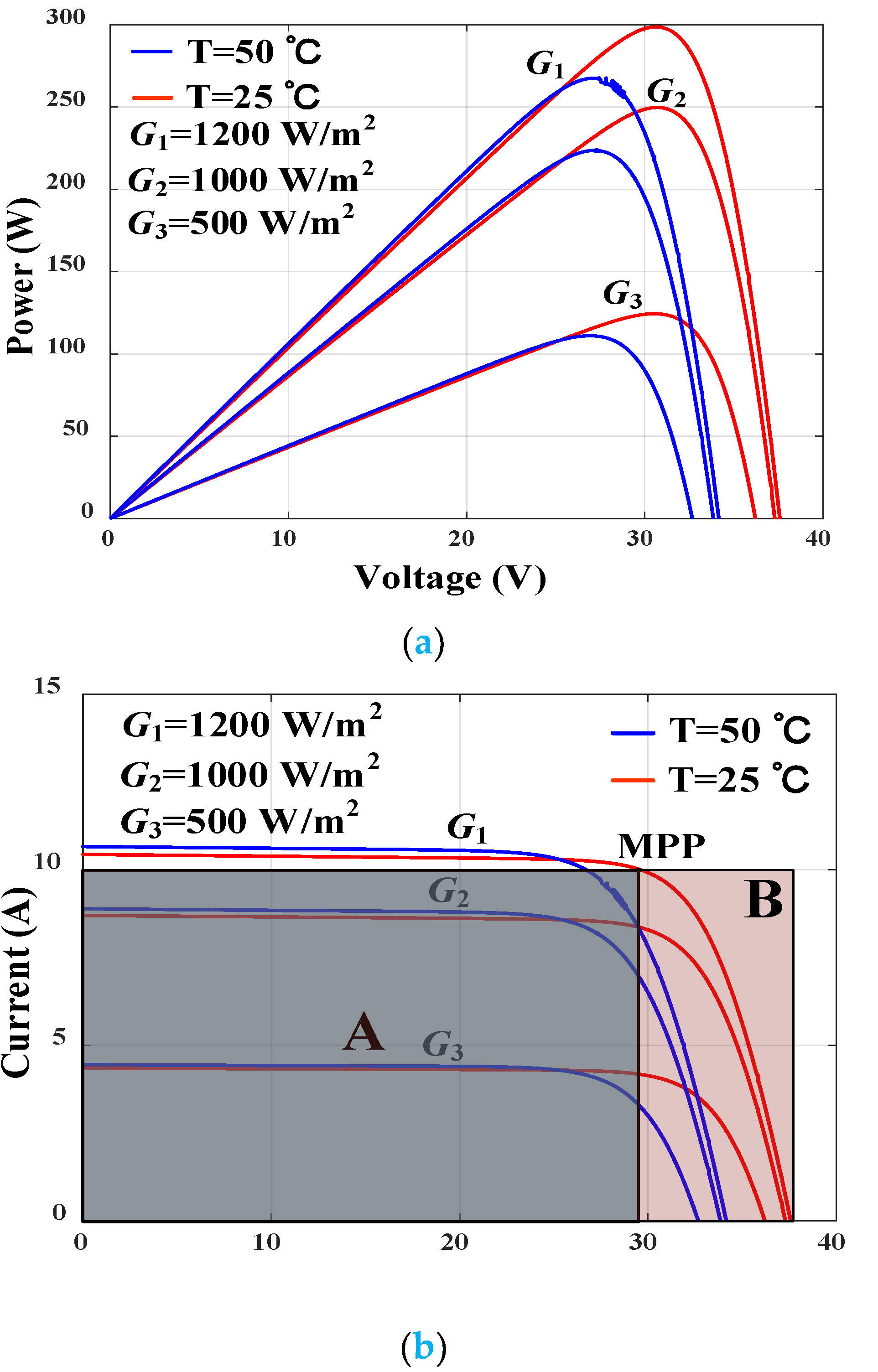
2.1. Mathematical Model of PV Array

The PV array has strong nonlinearity, and the MPP drifts with the irradiance level and ambient temperature [17]. The equivalent circuit of implicit PV arrays is given in Figure 2.
According to Kirchhoff Voltage Law (KVL), the output current of PV arrays can be described as follows:
I pv = N p I ph N p ( V pv + R s I pv ) / N s R sh N p I o { e x p [ q ( V p v + R s I p v ) / A K T N s ] 1 }
where Ipv represents the PV array current; Iph is the photocurrent; Io is the dark current; q is electron charge (q = 1.6 × 10⁻¹⁹ C); K is the Boltzmann constant (K = 1.38 × 10⁻²³ J/K); Rs is the series resistance; Rsh is the shunt resistance; A is the diode quality factor; T is the junction temperature; Ns and Np are the number of series and parallel PV cell, respectively. The dark current depends upon the temperature as given in Equation (2).
I o = I rs ( T / T s ) 3 e x p [ q E g / A K ( 1 / T n 1 / T ) ]
where Irs represents the reverse saturation current at standard test conditions (STC, Gref = 1000 W/m2, Tref = 25 °C); Eg is the bandgap energy. Equations (1) and (2) are transcendental equations, which are difficult to solve. Therefore, the open-circuit voltage (Voc), short-circuit current (Isc), MPP voltage (Vmpp) and MPP current (Impp) are frequently adopted to simplify the mathematical model of PV arrays in practical engineering, given by the following formula:
U oc = [ A K T I n ( I p h / I o + 1 ) ] / q I o = I sc e x p ( λ V o c ) V mpp = V m [ 1 c ( T T ref ) ] I n { e + b ( G / G ref - 1 ) } I mpp = I m I n { 1 + a ( T T ref ) } / G ref
where Vmpp and Impp represent the modified parameters; a, b and c are the corrected parameters. Figure 3 shows the P-V and I-V curves at various G and T.
As shown in Figure 3, the P-V and I-V curves are the unimodal function with only one MPP. In addition, the fill factor (FF) is commonly used to evaluate the dynamic quality of PV arrays [18], and the value of FF is usually between 60% and 80%, as shown in Equation (4). Since MPPT algorithms can maximize the extracted PV power, the working state of PV array can be as close to the MPP as possible by the MPPT algorithm. The MPP voltage of the PV array at various G and T is given in Figure 4.
F F = c 2 P mpp / ( I sc V oc ) = Area   A / Area   B

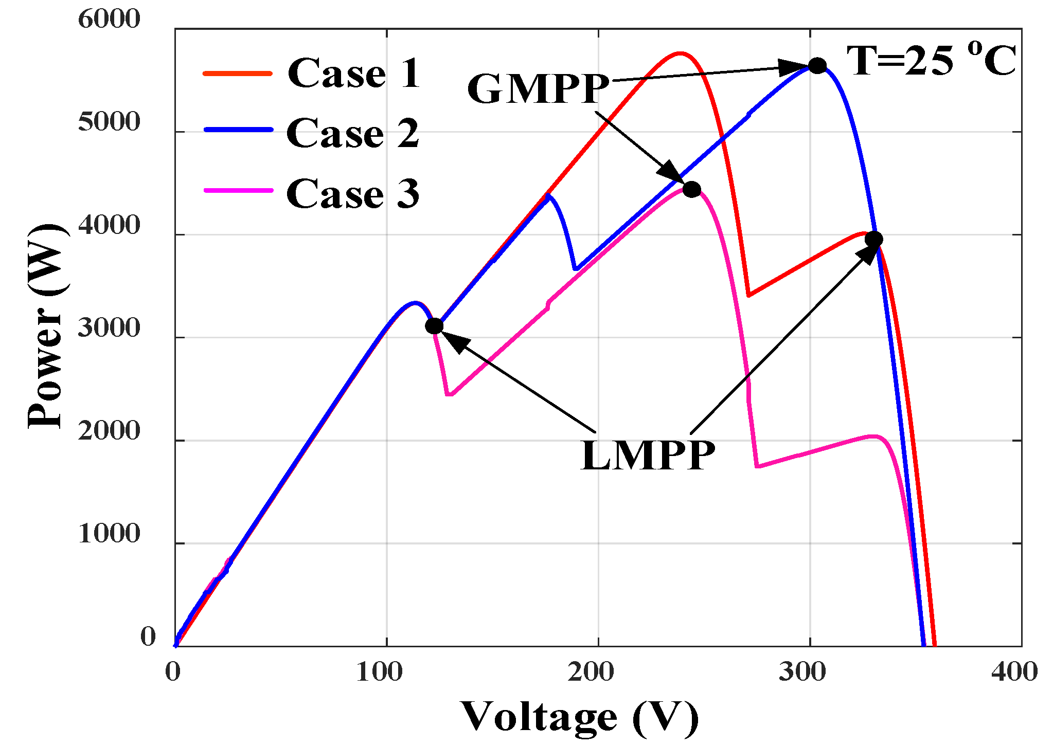
2.2. Modeling of PV Array at Partial Shading Conditions

PV arrays are usually installed at the top of buildings and in slope areas with a high north and low south. In engineering, many PV cells are often connected in series and parallel to form large PV arrays. Furthermore, environmental factors such as buildings, clouds and trees cause partial shading conditions (PSC), which affect the actual efficiency of PV systems, and even cause avalanches and hot spot effects [19]. However, most of conventional MPPT algorithms are unable to distinguish global MPP (GMPP) from local MPP (LMPP). Figure 5 shows the topological structure of a PV array at PSC.
In this study, five irradiance levels are used to simulate the PV array under PSC. The specific parameters of G are as follows: Case 1: 1000 W/m2, 800 W/m2, 400 W/m2; Case 2: 1000 W/m2, 800 W/m2, 600 W/m2; Case 3: 1000 W/m2, 200 W/m2, 600 W/m2. Table 1 shows the specifications of the PV array. The P-V curve under PSC is shown in Figure 6. The number of series-parallel PV cells is 2 and 4, respectively.

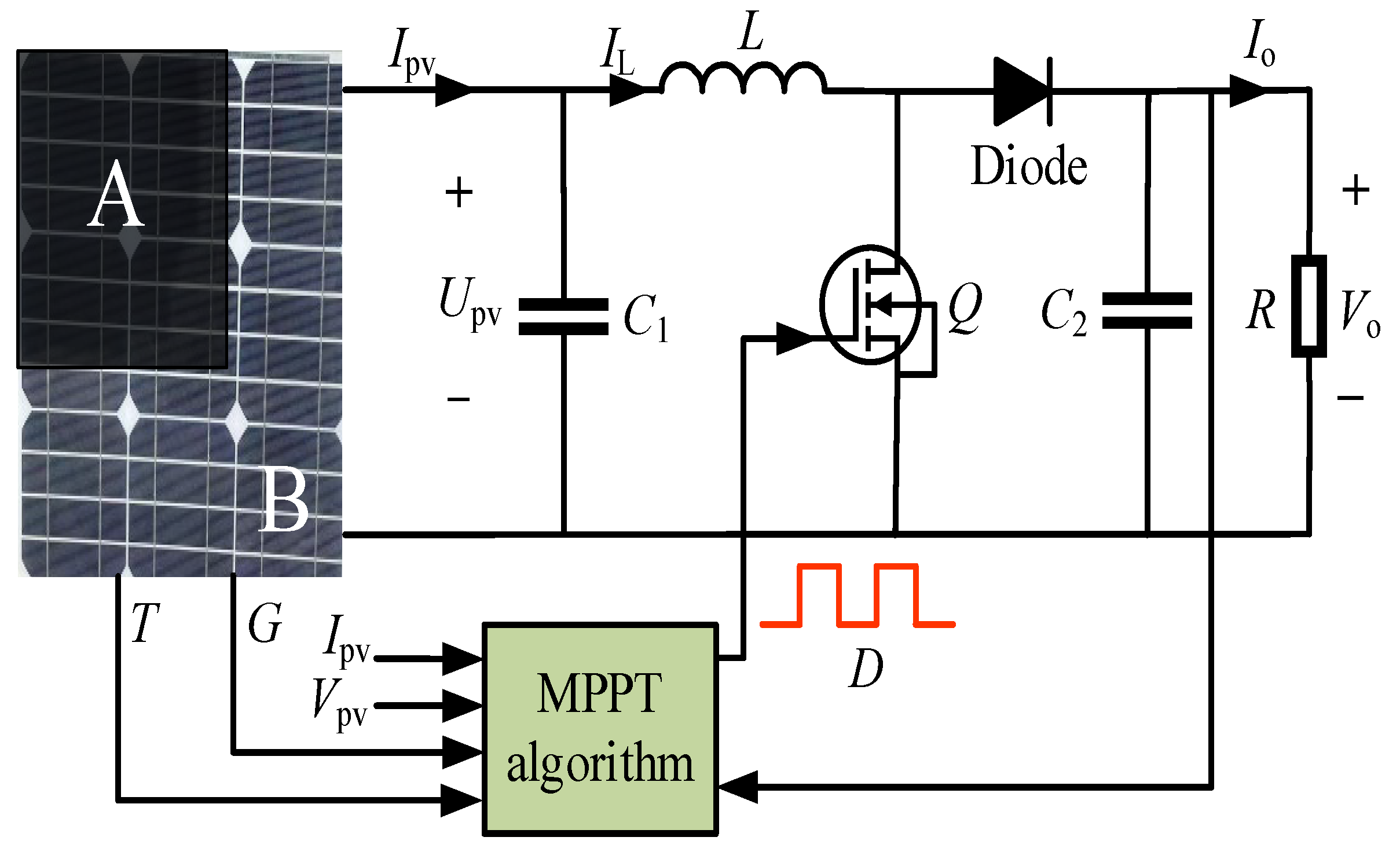
2.3. Mathematical Model of Boost Converter

Common DC–DC topological structures include buck-boost converters, boost converter, forward converters, Sepic converters, etc. Since boost converter has the advantages of low ripple and high operating efficiency, a PV system based on boost converter is built, as shown in Figure 7. The parameters of the boost converter are as follows: filter capacitor C1 = 500 × 10−6 F; boost inductor L = 0.008578 H; output capacitor C2 = 2.23 × 10⁻⁵ F; output resistance R = 20 Ω. To prevent the PV array from being in a mismatch state, the filter capacitor C1 and MPPT algorithm are employed to adjust the load transfer function and state space in real time and reduce energy losses [20]. In addition, the inductive current IL does not fluctuate with the G and T at steady-state conditions, i.e., Ipv = IL. Hence, the boost converter has continuous conduction mode (CCM), discontinuous conduction mode (DCM) and boundary conduction mode (BCM) working states.
According to the principle of volt-second balance, the state equation of the boost converter is as follows:
d I pv / d t = ( V pv V o ) / L + μ V o / L + ε 1 d V pv / d t = ( I pv I L ) / C 1 + ε 2 d V o / d t = U o / ( R C 2 ) + ( 1 μ ) I pv / C 2 + ε 3
ε 1 = L Δ V pv ( V pv + ( μ 1 ) V o ) Δ L L ( L + Δ L ) ε 2 = C 1 I L Δ C 1 I pv C 1 ( C 1 + Δ C 1 ) ε 3 = ( μ 1 ) V o Δ C 2 C 2 + Δ C 2 + ( R Δ C 2 + C 2 Δ R + Δ R Δ C 2 ) V o ( R C 2 + R Δ C 2 + C 2 Δ R + Δ R Δ C 2 ) R C 2
where IL represents the inductor current; C1 is the capacitor filter; Vpv is the PV array voltage; Ipv is the PV array current; L is the boost inductor; Vo is the output voltage; Io is the output current; D is the duty cycle; ε is the disturbance quantity; μ is the switch value. If μ = 1, the switch Q is turned on; If μ = 0, the switch Q is turned off. Moreover, a general nonlinear system state equation for PV systems is shown in Equation (7).
x ˙ = F ( x , u , t ) = f ( x , t ) + μ [ g ( x , t ) + ε ]
where g ( x , t ) = [ V o / L , 0 , I o / L ] T ; x ˙ = [ I ˙ pv , U ˙ pv , U ˙ o ] T ; f(x, t) = [(VpvVo), (IpvIL)/C1, (ILIo)/C2]T.

3. Improved SMC Strategy

Variable structure control (VSC) tracks the MPP continuously during reaching and sliding processes according to the characteristic variables and discontinuity switching quantities of the PV system. The SMC controller has been widely used in PV systems due to the characteristics of compact structure, no need for online identification and strong anti-buffeting ability [21,22]. However, the traditional SMC has some problems, such as large inertia of the system and dead zone of state quantity, which leads to poor robustness of PV systems and significant power chattering in finite time. Therefore, a novel sliding surface and multi power reaching law are constructed to improve the reaching rate and robustness of the conventional SMC strategy in this paper. The main design steps of the SMC algorithm are as follows: (1) A proper sliding surface is selected; (2) the equivalent control (μeq) is solved based on the state equation; (3) a sliding reaching law is designed; (4) the Liapunov function is employed to analyze the reachability, existence and stability of the SMC strategy. The principle of the SMC strategy is given in Figure 8.

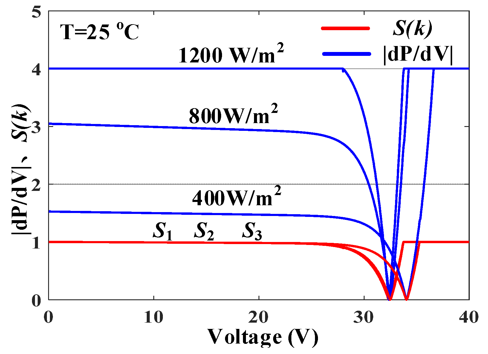
3.1. Improvement of Sliding Surface

In order to implement chattering-free SMC, it is very important to select a suitable sliding mode surface (S) to improve the rapidity and control quality of sliding mode controls. Currently, dP/dV is commonly selected as the sliding surface of the conventional SMC strategy [23]. Although the method is able to satisfy the reachability and stability of SMC, there is a time and space lag during handoff process. Additionally, it is accompanied by high-frequency buffeting, which easily causes the instability of PV systems. To overcome the above drawbacks in conventional SMC, a novel sliding surface S(k) for MPPT is designed, as expressed by Equation (8). Figure 9 shows the characteristic curves of |dP/dV| and S(k).
S ( k ) = c x ˙ = 1 / I p v ( d P pv / d V pv ) = 1 + U pv / I pv ( d I pv / d V pv )
where polynomial S(k) satisfies the Hurwitz stability condition; p is the Laplace operator.
As shown in Figure 9, the sliding surfaces S1, S2 and S3 are the characteristic curves for various irradiance values at a temperature of 25 °C. The amplitude range of |dP/dV| is large and the reaching process is not smooth when G changes from 1200 W/m2 to 800 W/m2 and then to 400 W/m2. However, the proposed sliding surface S(k) gradually decreases until the time derivative of MPP is zero, and then the S(k) is normalized, i.e., S(k) ∈ [0,1]. If the sliding surface S(k) > 0, the working point is located on the left side of MPP. The switch tube Q is turned on (μ = 1) to compel the working point toward MPP. If the sliding surface S(k) < 0, the working point is located on the right side of MPP, and the switch tube Q is turned off (μ = 0) to compel the working point toward MPP. Therefore, the switching function is defined as follows:
μ = μ + Δ μ ,   S ( k ) > 0 μ Δ μ ,   S ( k ) < 0 μ ,   S = 0

3.2. Selection of Control Law

In this study, a sliding reaching law combining equivalent control μeq with compensation control μsw is employed to improve the convergence of SMC, which can be expressed by:
μ = μ eq + μ sw
where equivalent control μeq is the dynamic portion to ensure the asymptotic stability and invariability of SMC; compensation control μsw is adopted to overcome the non-ideal factors of indeterminacy and additional disturbance. The proof procedures of reachability, existence and the convergence of control law can be expressed as follows:
S ˙ = S / t = S d x / ( d t x T ) + d S / d t = S x ˙ / x T + d S / d t
According to Equation (6), Equation (10) can be rewritten as follows:
S ˙ = S f ( x , t ) / x T + S g ( x , t ) μ / x T + S μ ε / x T + d S / d t
Equivalent control μeq is often designed for deterministic non-interference systems, so the disturbance quantity term ε is ignored. The equivalent control μeq is shown in Equation (13). In addition, Equation (11) needs to satisfy the local convergence of Fillpov.
μ eq = [ S g ( x , t ) / x T ] - 1 [ S f ( x , t ) / x T + d S / d t ]
Substitute Equations (9) and (11) into Equation (12), the equivalent control and derivative of sliding surface are given as follows:
S ˙ = μ sw S / x T g ( x , t ) μ eq = 1 V pv / V o
According to the Liapunov stability criterion [24], the reachability can be expressed by:
S S ˙ = S ( x , t ) μ s w S / x T g ( x , t ) < σ

3.3. Multi-Power Reaching Law
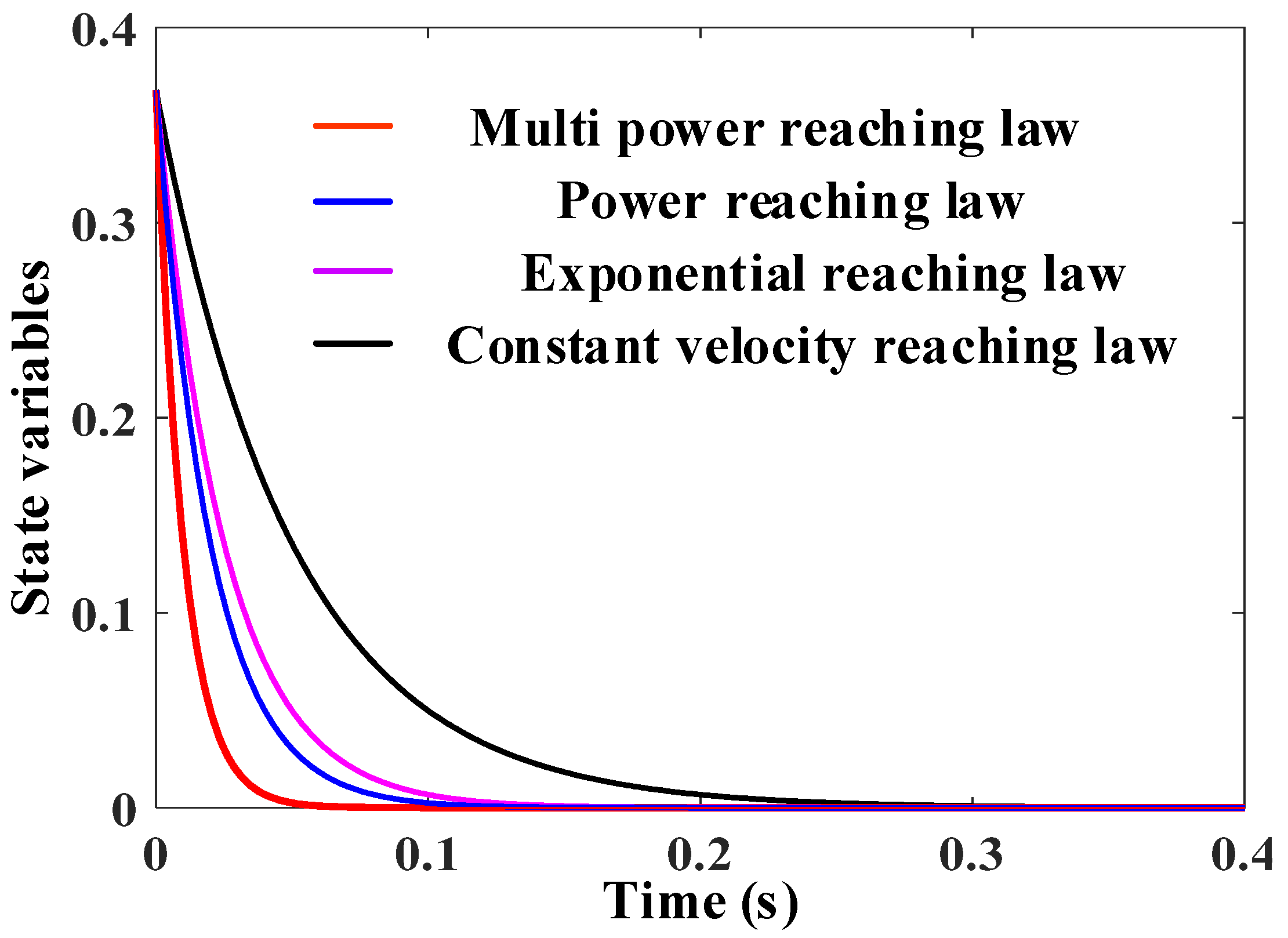
Reachability only guarantees that any working point in the state space can reach the sliding surface S(k) in finite time, and no specific path is constrained and planned. The sliding reaching law has a strong influence on the dynamic quality, robustness and stability of PV systems. Therefore, a multi-power reaching law based on the conventional sliding reaching law is presented, and the sigmoid function is used to replace the symbolic function in the multi-power reaching term. The conventional sliding reaching laws are given by Equations (16)–(18).
  • Constant velocity reaching law:
    S ˙ = ε Sgn ( S )   ε > 0
    where ε represents the reaching rate. The constant velocity reaching law has characteristics of simplicity and expansion. However, the reaching rate is a fixed value and the convergence is incompatible with system buffeting in SMC structures [25].
  • Exponential reaching law:
    S ˙ = ε Sgn ( S ) k S   ε > 0 ,   k > 0
    where −kS represents the exponential reaching term, and the numerical solution is S = S(0)ekt. The exponential reaching law reduces the reaching time and system inertia of SMC by using the exponential reaching term. However, reaching the sliding surface is an asymptotic process with finite convergence [26].
  • Power reaching law:
    S ˙ = k | S | a Sgn ( S )   ε > 0 , 0 < a < 1
    where −k|S|a is the power term. The power reaching law reaches to the sliding surface S with a great velocity by adjusting the power exponent a, yet the system state trajectory is stabilized in the neighborhood of origin. In addition, in the power reaching law exists a quantitative feedback gain, which deteriorates the buffeting of PV systems. In addition, there are trailing currents and parasitic diodes in the switching tube Q, and the symbolic function (sgn) is an ideal switching characteristic and the switching action has hysteresis and trailing phenomenon, which further exacerbates the dead zone range of the state quantity and the switching discontinuity [27]. To solve the problems mentioned above, a multi-power sliding reaching law is proposed, in which the sigmod function is used to replace the sgn function to improve the dynamic control quality of PV systems. Figure 10 shows the sigmoid, sat and sgn functions. A multi-power reaching law is defined in Equation (19).
S ˙ = k 1 | S | α Sigmoid ( S ) k 2 | S | β Sigmoid ( S ) k 3 f ( S ) Sigmoid ( S ) - k 4 | S | γ S f ( S ) = 1 / [ ( 1 λ ) e k 5 | S | η + λ ]
where k1 > 0; k2 > 0; k3 > 0; k4 > 0; k5 > 0; α > 1; 0 < β<1; 0 < λ<1; η > 0. The value range of η is shown in Equation (20).
η = max ( α , | S | ) ,   | S | 1 min ( β , | S | ) ,   | S | < 1
According to the exponential sliding mode property, the multi-power reaching law is mainly bounded by −k2|S|βSigmoid(S) − k3f(S)Sigmoid(S) when the value of |S| < 1. Moreover, the exponential reaching term k3f(S) is adopted to replace the reaching rate ε in conventional exponential reaching law. The value of |S| is larger during the reaching process, f(S) 1/λ. It is noted that the k3f(S) far outweighs ε and the reaching rate of SMC has been greatly improved. During the sliding process, the value of |S| tends to zero and f(S) 1. Afterward, k3f(S) approaches ε rapidly to achieve chattering-free SMC and adaptive control. When the value of |S| ≥ 1, the multi-power reaching law is mainly constrained by −k2|S|αSigmoid(S) − k3f(S)Sigmoid(S), and the sliding process is smoother.
In order to verify the reachability and existence of SMC, a negative semidefinite function is constructed based on the Liapunov function.
V = S 2 / 2 > 0
Substitute Equations (15) and (19) into Equation (21), and the time derivative of Liapunov function is as follows:
V ˙ = S S ˙ = k 1 | S | α + 1 k 2 | S | β + 1 k 3 f ( S ) S k 4 | S | γ + 2 0
It can be seen from the Equation (21) that the system state variables become close to MPP of PV systems rapidly in the process of reaching and sliding, and only when S = 0, S S ˙ = 0 .
Thus, the multi-power sliding mode reaching law is used in this study, as given in Equation (23).
μ s w = k 1 | S | α Sigmoid ( S ) k 2 | S | β Sigmoid ( S ) k 3 f ( S ) Sigmoid ( S ) k 4 S | S | γ
In addition, the value of switching function μ is within [0,1] and the control law can be defined as follows:
μ = 1 ,   μ 1 1 V pv / V o + μ sw ,   0 < μ < 1 0 ,   μ 0

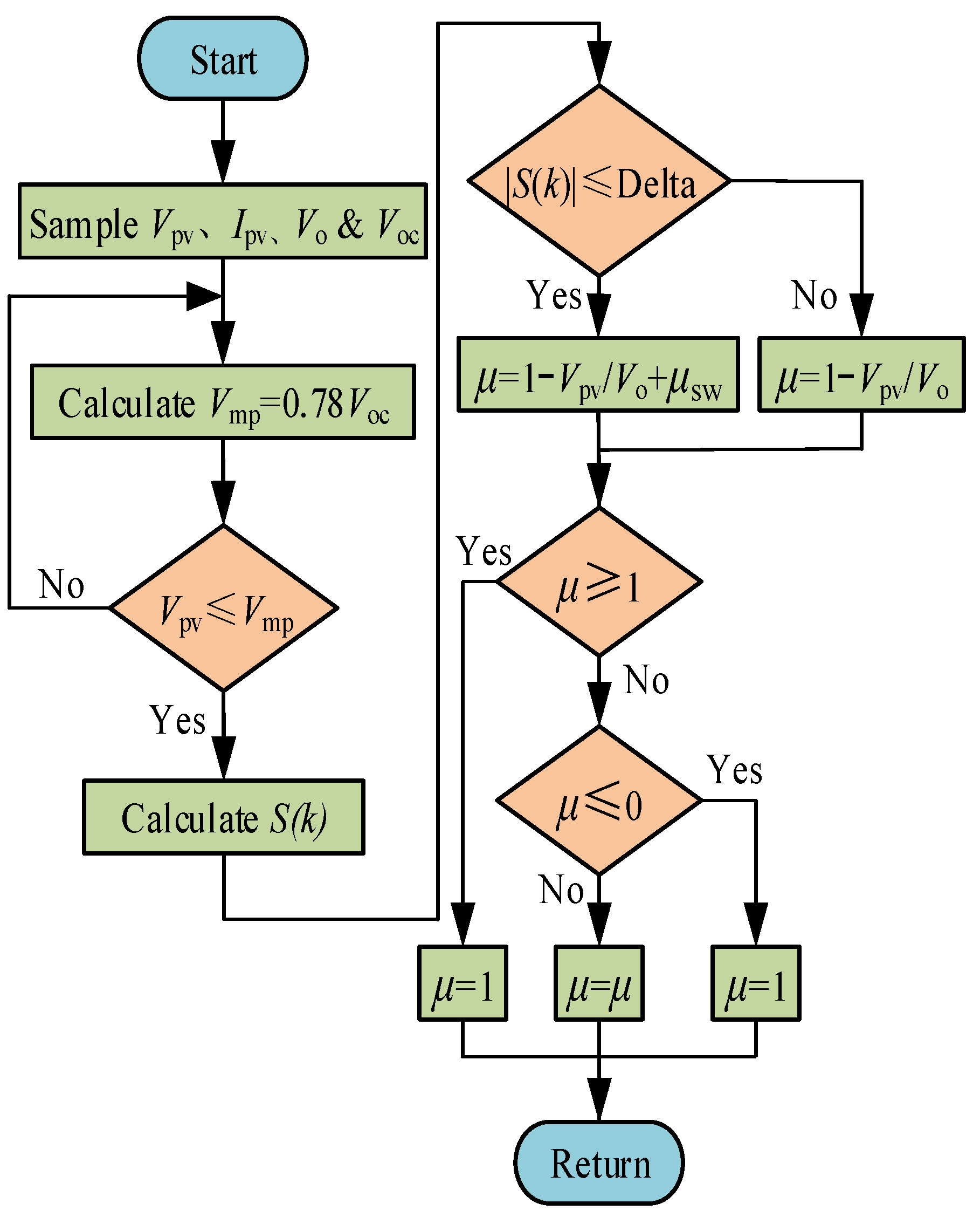
3.4. The Flowchart of Improved SMC Strategy

Equation (8) can be rewritten as follows:
S ( k ) = 1 / I p v ( P pv / V pv ) = 1 / I p v [ P p v ( n ) P p v ( n 1 ) ] / [ V p v ( n ) V p v ( n 1 ) ]
S(k) = 0 is difficult to achieve due to the high logical numerical conversion and high-precision numerical operations of computers, especially in digital control systems. Therefore, a bandwidth throttling strategy needs to be imposed on the sliding surface S(k), i.e., −Delta ≤ S(k) ≤ Delta (Delta ≤ 0.05). The flowchart of improved SMC algorithm is shown in Figure 11. Figure 12 shows the reaching time at various reaching laws.
As shown in Figure 12, the improved SMC strategy with multi-power reaching law has an excellent tracking performance, and the buffeting amplitude of the proposed strategy is observably suppressed. It is clearly seen that the three compared SMC strategies do not contain multi-power terms, and the time from the initial point to the sliding mode surface is long. Meanwhile, the convergence performance is poor, and the system cannot be stabilized near the MPP of PV systems. Figure 13 shows the state variables at various reaching laws.
As shown in Figure 13, since the improved SMC strategy has two adjustable power terms, the reaching and sliding process has better dynamic quality and faster convergence rates than the conventional SMC strategy. Moreover, the first-order term k4S|S|γ is added to accelerate the speed of the system away from the sliding surface S(k). Compared with the three sliding mode control methods, although the control variables can converge with the system changes, the chattering is obvious and the convergence is poor.
It is suggested that the improved SMC strategy has a better control quantity and convergence rate, and it can quickly respond to the external environment without buffeting.

4. Simulation Results and Discussions

Since the PV array has severe nonlinearity and the MPP drifts with the irradiance level and ambient temperature, the improved SMC, exponential SMC and constant velocity SMC algorithms are applied under dynamic and PSC by using the Matlab/Simulink. Moreover, the control quality and tracking performance of three compared algorithms are compared and analyzed in detail. The circuit diagram of the proposed system is given in Figure 1. In addition, the experimental platform is constructed to illustrate the feasibility and superiority of the proposed MPPT algorithm.

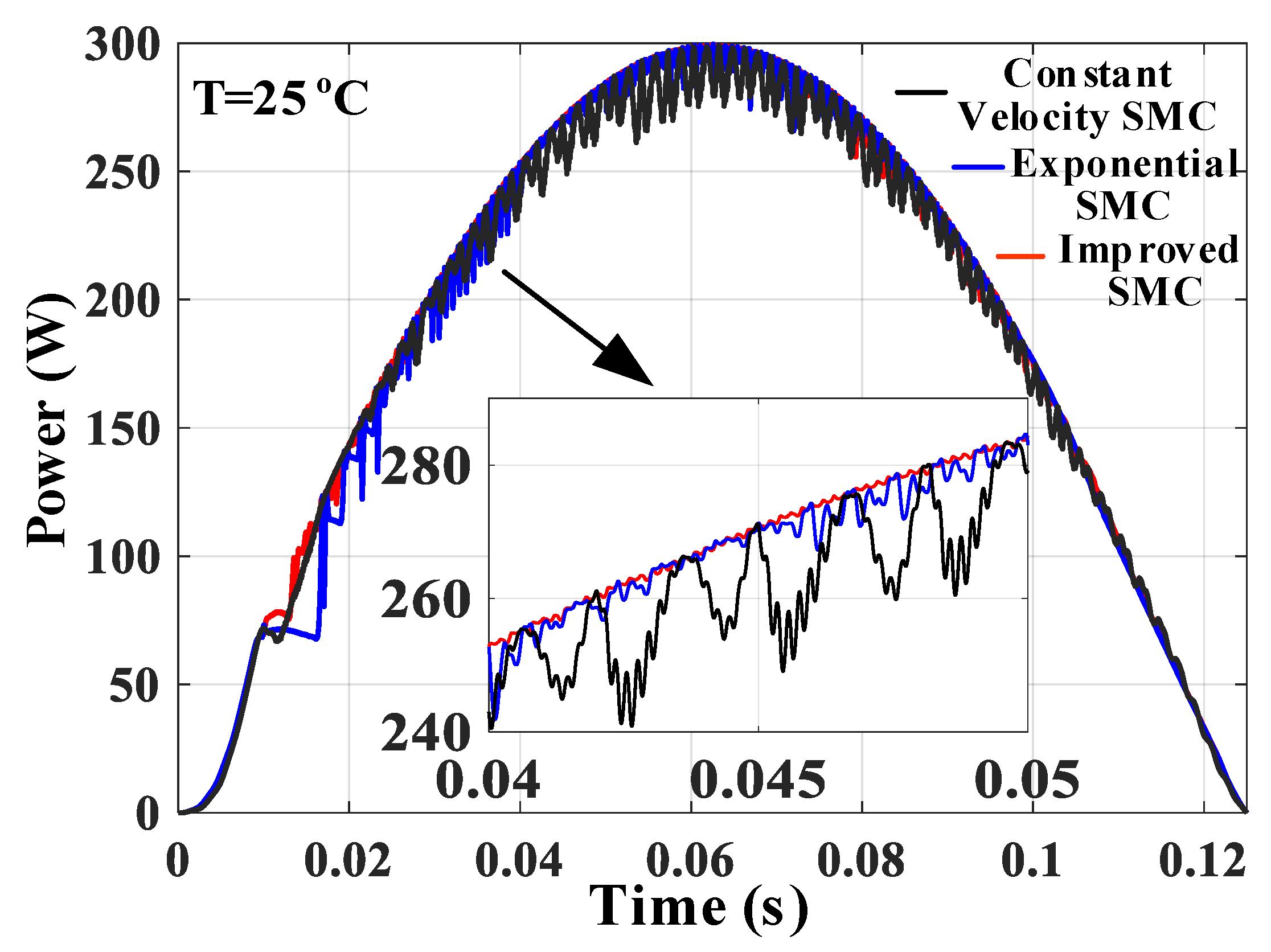
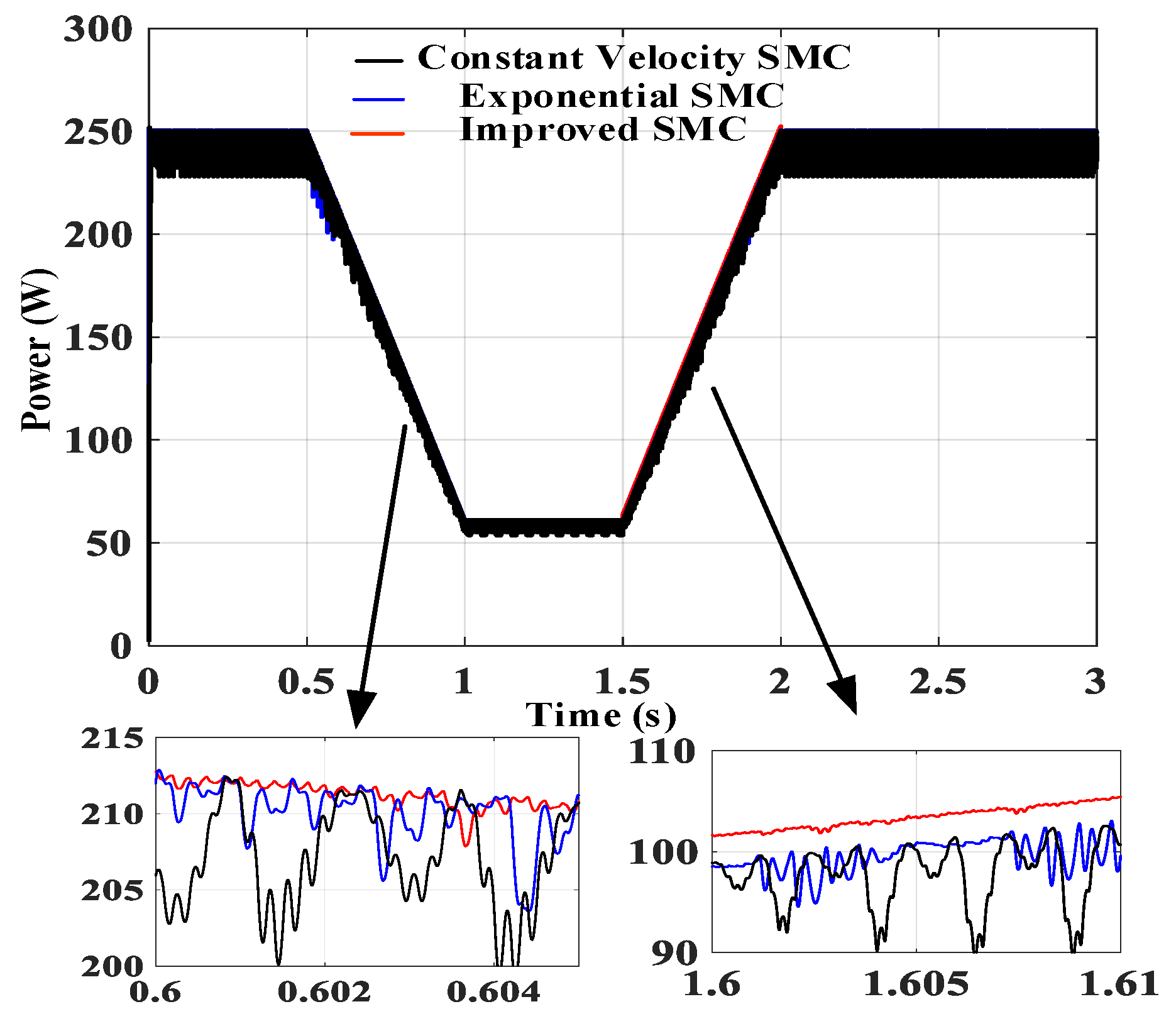
4.1. MPPT Tracking Performance at Dynamic Condition

In practical situations, the irradiance level varies more frequently, and the irradiance level affects the extracted PV power more than ambient temperature. To verify the response speed and stabilization accuracy of the improved SMC strategy, an irradiance curve is constructed with reference the total average daily irradiance in a region of Western China. In this case, the specific parameters of irradiance (T = 25 °C) are as follows: In 0 s~0.065 s, G increases from 0 W/m2 to 1200 W/m2; in 0.065 s~0.125 s, G decreases from 1200 W/m2 to 0 W/m2. Figure 14 shows the MPPT curve for various G (T = 25 °C).
As shown in Figure 14, the power waveforms of the exponential SMC and constant velocity SMC for MPPT algorithms are always in oscillatory states. Consequently, in 0.04 s~0.05 s, the amplitude range of two compared algorithms is 239.6 W~280.3 W and 238.9 W~278.7 W, respectively. Under the same condition, it can be seen that the improved SMC algorithm has a better tracking performance, and the waveform is smoother without power chattering.
To illustrate the tracking effect of the proposed MPPT algorithm, the regression statistics method is used for analysis, shown in Figure 13. The results of regression analysis are shown in Table 2. The multiple correlation coefficient represents the linearity between variables; the complex determination coefficient indicates the fitting effect. It can be seen from Table 2 the proposed MPPT algorithm is more stable from the irradiance changes, and the fitting between them is better.
Usually, under variable atmospheric conditions, irradiance and climate temperature have variability and irregular periodicity. Therefore, the three MPPT algorithms are employed to track the MPP under the conditions that both irradiance and temperature changes. The parameters of G, T are as follows: In 0 s~0.05 s, G = 500 W/m2, T = 15 °C; In 0.051 s~0.1 s, G = 1000 W/m2, T = 25 °C; In 0.11 s~0.15 s, G = 800 W/m2, T = 20 °C. Figure 15 shows the MPPT curve under varying G, T.
As can be seen from Figure 15, the tracking times of exponential SMC algorithm to MPP are 0.0026 s and 0.0029 s when G changes from 500 W/m2 to 1000 W/m2 and then to 800 W/m2. In contrast, the tracking times of the constant velocity SMC algorithm are 0.0045 s and 0.0047 s under the same atmospheric conditions. It is worthwhile to note that the tracking times of the improved SMC algorithm are 0.0016 s and 0.0017 s in the same conditions. In addition, the output powers of the two compared algorithms are always in oscillatory states until the end of simulation. In 0.07 s~0.075 s, the amplitude range of two compared SMC algorithms is 241.3 W~249.6 W and 229.1 W~249.3 W, respectively. Obviously, the improved SMC algorithm has a stronger response speed and anti-buffeting ability with smoother waveform.
To further verify the effectiveness of the proposed MPPT algorithm, the proposed MPPT algorithm is applied under ramp G, T. The parameters of G, T are as follows: In 0 s~0.5 s, G = 1000 W/m2, T = 25 °C; in 1 s~1.5 s, G decreases from 1000 W/m2 to 200 W/m2, T decreases from 25 °C to 5 °C; in 1.5 s~2 s, G increases from 200 W/m2 to 1000 W/m2, T increases from 5 °C to 25 °C; In 2 s~3 s, G = 1000 W/m2, T = 25 °C. The MPPT curve under ramp G, T are given in Figure 16.
As shown in Figure 16, the stabilization accuracy of the exponential SMC and constant velocity SMC is 3.8% and 5.4%, respectively. In contrast, the stabilization accuracy of the proposed MPPT algorithm is 1.1%. It is clearly seen that the proposed MPPT algorithm has better stability and tracking characteristics. Figure 17 shows the efficiency curve under varying G, T.
It can be seen from Figure 17, when G changes from 500 W/m2 to 1000 W/m2 and then to 800 W/m2, the efficiency of the exponential SMC algorithm is 96.6% and 95.5%, respectively. In contrast, the efficiency of the constant velocity SMC algorithm is 89.3% and 80.3%, respectively. From an efficiency viewpoint, the efficiency of proposed algorithm has increased by 1.4% and 2.8%, respectively, compared with the exponential SMC algorithm.
In summary, the improved SMC strategy can nearly maximize the extracted PV power under dynamic conditions. Moreover, the proposed strategy has better tracking performance, stabilization accuracy and efficiency compared to the exponential SMC and constant velocity SMC strategies.

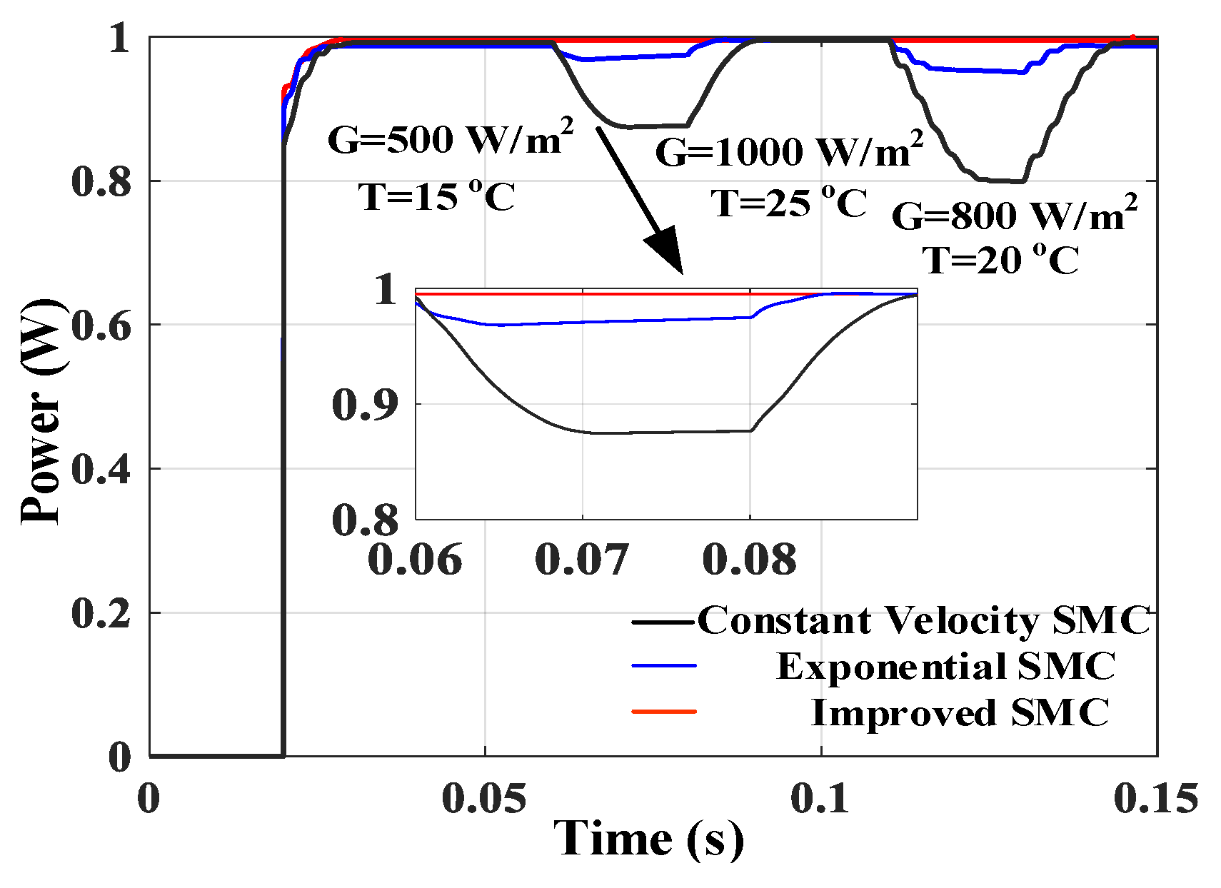
4.2. MPPT Tracking Performance at PSC

The environmental factors such as trees, buildings and clouds cause the PSC. However, the conventional MPPT algorithm is unable to efficiently distinguish the GMPP and LMPP of PV systems, which implies a great loss of energy. To further test and validate the superiority of the proposed SMC strategy, the tracking performance of the three MPPT algorithms is compared under the condition of case 1, which is given in Figure 6. The MPPT curve under PSC is given in Figure 18.
As shown in Figure 18, the exponential SMC and constant velocity SMC algorithms are unable to track the GMPP, and the PV system falls into LMPP. Therefore, the output power of two compared algorithms is 5100 W and 3300 W, respectively. In addition, the output power of the improved SMC algorithm is 5766 W, and the amplitude range is lower.
In conclusion, compared with exponential sliding mode and constant speed sliding mode algorithms, the PV MPPT algorithm with improved sliding mode control strategy has good tracking characteristics, stable accuracy and efficiency, strong anti-perturbation ability and less chattering, whether in dynamic or shading conditions. The proposed strategy can work properly under any meteorological condition.

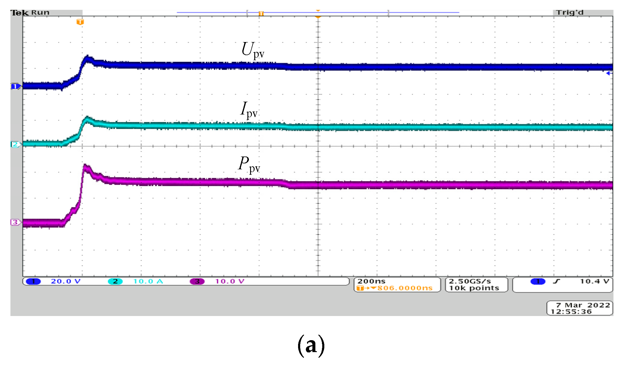
5. Experimental Results

In this study, a PV experimental platform was built in the laboratory to verify the feasibility and superiority of the proposed MPPT algorithm. The experimental platform, shown in Figure 19, mainly consists of a PV cell, MPPT controller, boost converter and load. Moreover, the proposed algorithm is compared with the exponential SMC algorithm under changing G.
In this experiment, 12 groups of lights are used to simulate the actual solar irradiance changes. Figure 20 shows the experimental waveforms of the MPPT algorithm under changing G. As shown in Figure 20, the proposed MPPT algorithm and exponential SMC algorithm can efficiently track the MPP of the PV cell. In Figure 20a, the tracking time of the proposed MPP algorithm is 14 ms, which has a good anti-interference ability. In contrast, the tracking time of the exponential SMC algorithm is 28 ms. Experimental results show that the proposed algorithm has better tracking characteristics and response speed, and the waveform is smoother.
In conclusion, the proposed MPPT algorithm has stronger tracking characteristics and stability. At the same time, the proposed algorithm can quickly respond to external conditions and has better robustness and universality.

6. Conclusions

SMC controllers have been widely used in PV systems due to the characteristics of compact structure and strong anti-buffeting ability. Hence, a novel MPPT algorithm based on SMC for PV systems is proposed in this paper. Compared with the exponential SMC and constant velocity SMC algorithms, a novel sliding surface 1/Ipv×(dPpv/dVpv) is proposed to improve the reaching rate and robustness of the conventional SMC strategy. In addition, an improved SMC structure with a multi-power reaching law is designed to improve the control quality and convergence rate of SMC. Meanwhile, the sgn function is replaced by the sigmoid function for improving the linear feedback ability of PV systems, and the Liapunov function is employed to prove the reachability, existence and stability of the improved SMC strategy.
Consequently, Matlab/Simulink is used to construct the proposed PV system. The improved SMC strategy is compared and analyzed with the exponential SMC and constant velocity SMC algorithm to verify the validity and feasibility of the proposed strategy. Simulation results show that, whether under the dynamic or PSC, the improved SMC strategy has better tracking performance, stabilization accuracy and efficiency with less power buffeting. The proposed MPPT algorithm has stronger robustness and universality. Additionally, the efficiency of the proposed algorithm is improved by 2.3% and 5.6% as compared to the exponential SMC algorithm and constant velocity SMC algorithm, respectively. Moreover, it is beneficial to improve the control quality of MPPT algorithm in complex environments, and the proposed algorithm has been verified by experiments. The future work will adopt the backstepping controller to estimate the thickness of the boundary layer to further improve the convergence rate of SMC. In the meantime, we will concentrate on the application of the SMC strategy.

Author Contributions

Y.Z. and Y.-J.W. conceived of the presented idea design and simulation; Y.Z. carried out testing and verification; Y.Z. wrote the original draft of this article; Y.Z., Y.-J.W. and J.-Q.Y. reviewed and edited this article; Y.-J.W. and J.-Q.Y. supervised the findings of this work. All authors provided critical feedback and helped shape the research, analysis, and manuscript. All authors have read and agreed to the published version of the manuscript.

Funding

This study was supported by the National Natural Science Foundation of China (grant: 61503169, 61802161) and the Natural Science Foundation of Liaoning province (grant: 2020-MS-291).

Institutional Review Board Statement

Not applicable.

Informed Consent Statement

Not applicable.

Data Availability Statement

The data presented in this study are not publicly available due to privacy issues.

Acknowledgments

The authors would like to thank the National Natural Science Foundation of China and the Natural Science Foundation of Liaoning province for the scholarships with key codes 61503169, 61802161 and 2020-MS-291.

Conflicts of Interest

The authors declare no conflict of interest.

Abbreviations

PVphotovoltaic
MPPmaximum power point
MPPTmaximum power point tracking
P&Operturbation and observation
INCincremental conductance
Girradiance
Ttemperature
STCstandard test conditions (G = 1000 W/m2, T = 25 °C)
ANNartificial neural network
SMCsliding model control
Satsaturation function
PSCpartial shading condition
Dduty cycle
KVLKirchhoff Voltage Law
Iscshort-circuit current
Vocopen-circuit voltage
Imppmaximum power point current
Vmppmaximum power point voltage
FFfill factor
GMPPglobal maximum power point
LMPPlocal maximum power point
CCMcontinuous conduction mode
BCMboundary conduction mode
DCMdiscontinuous conduction mode
ssliding mode surface
S(k)proposed sliding mode surface
Sgnsymbolic function

References

  1. Bollipo, R.B.; Mikkili, S.; Bonthagorla, P.K. Hybrid, optimal, intelligent and classical PV MPPT techniques: A review. CSEE J. Power Energy 2020, 7, 9–33. [Google Scholar]
  2. Eltamaly, A.M. A novel musical chairs algorithm applied for MPPT of PV systems. Renew. Sust. Energ. Rev. 2021, 146, 111135–111148. [Google Scholar] [CrossRef]
  3. Priyadarshi, N.; Padmanaban, S.; Holm-Nielsen, J.B.; Blaabjerg, F.; Bhaskar, M.S. An experimental estimation of hybrid ANFIS–PSO-based MPPT for PV grid integration under fluctuating sun irradiance. IEEE Syst. J. 2019, 14, 1218–1229. [Google Scholar] [CrossRef]
  4. Podder, A.K.; Roy, N.K.; Pota, H.R. MPPT methods for solar PV systems: A critical review based on tracking nature. IET Renew. Power Gen. 2019, 13, 1615–1632. [Google Scholar] [CrossRef]
  5. Mansoor, M.; Mirza, A.F.; Ling, Q. Harris hawk optimization-based MPPT control for PV systems under partial shading conditions. J. Clean. Prod. 2020, 274, 122857–122871. [Google Scholar] [CrossRef]
  6. Valenciaga, F.; Inthamoussou, F.A. A novel PV-MPPT method based on a second order sliding mode gradient observer. Energy Convers. Manag. 2018, 176, 422–430. [Google Scholar] [CrossRef]
  7. Mirz, A.F.; Mansoor, M.; Ling, Q.; Yin, B.; Javed, M.Y. A Salp-Swarm Optimization based MPPT technique for harvesting maximum energy from PV systems under partial shading conditions. Energy Convers. Manag. 2020, 209, 112625–112637. [Google Scholar] [CrossRef]
  8. Shao, W.Q.; Wang, M.; Wu, C.Q.; Cheng, Y.; Liu, Y.L. MPPT control strategy based on improved sliding mode control for photovoltaic power system. Acta Energy Sol. Sin. 2021, 42, 87–93. [Google Scholar]
  9. Li, Z.M.; Shan, X.C.; Xu, P.K. Super-twisting sliding mode controller used in photovoltaic system MPPT. Power Syst. Prot. Control. 2018, 46, 32–37. [Google Scholar]
  10. Luo, D.; Zheng, J.D. MPPT technology based on improved sliding mode control. Electr. Drive 2017, 47, 63–66. [Google Scholar]
  11. Nadeem, A.; Sher, H.A.; Murtaza, A.F.; Ahmed, N. An online fractional open-circuit voltage maximum power point tracking (MPPT) algorithm based on sliding mode control. In Proceedings of the 2020 International Symposium on Recent Advances in Electrical Engineering & Computer Sciences (RAEE & CS), Islamabad, Pakistan, 20–22 October 2020; Volume 5, pp. 1–6. [Google Scholar]
  12. Latifi, M.; Abbassi, R.; Jerbi, H.; Ohshima, K. Improved krill herd algorithm based sliding mode MPPT controller for variable step size P&O method in PV system under simultaneous change of irradiance and temperature. J. Franklin. Ist. 2021, 358, 3491–3511. [Google Scholar]
  13. Khan, Z.A.; Khan, L.; Ahmad, S.; Mumtaz, S.; Jafar, M.; Khan, Q. RBF neural network based backstepping terminal sliding mode MPPT control technique for PV system. PLoS ONE 2021, 16, e0249705. [Google Scholar] [CrossRef]
  14. Rafika, E.L.; Abbou, A.; Mokhlis, M.; Bouzakri, H. Real-Time implementation of a PV system maximum power point tracking based on the ANN-Backstepping sliding mode control. Int. J. Renew. Energy Res. 2021, 11, 1959–1967. [Google Scholar]
  15. Nkambule, M.S.; Hasan, A.N.; Ali, A.; Hong, J.; Geem, Z.W. Comprehensive evaluation of machine learning MPPT algorithms for a PV system under different weather conditions. J. Electr. Eng. Technol. 2021, 16, 411–427. [Google Scholar] [CrossRef]
  16. Ali, A.I.M.; Mohamed, H.R.A. Improved P&O MPPT algorithm with efficient open-circuit voltage estimation for two-stage grid-integrated PV system under realistic solar radiation. Int. J. Elec. Power 2022, 137, 107805–107827. [Google Scholar]
  17. Mansoor, M.; Mirza, A.F.; Ling, Q.; Javed, M.Y. Novel Grass Hopper optimization based MPPT of PV systems for complex partial shading conditions. Sol. Energy 2020, 198, 499–518. [Google Scholar] [CrossRef]
  18. Abdel-Salam, M.; El-Mohandes, M.T.; Goda, M. An improved perturb-and-observe based MPPT method for PV systems under varying irradiation levels. Sol. Energy 2018, 171, 547–561. [Google Scholar] [CrossRef]
  19. Chai, L.G.K.; Gopal, L.; Juwono, F.H.; Chiong, C.W.; Ling, H.C.; Basuki, T.A. A novel global MPPT technique using improved PS-FW algorithm for PV system under partial shading conditions. Energy Convers. Manag. 2021, 246, 114639–114653. [Google Scholar] [CrossRef]
  20. Zhou, Y.; Ho, C.N.M.; Siu, K.K.M. A fast PV MPPT scheme using boundary control with second-order switching surface. IEEE J. Photovolt. 2019, 9, 849–857. [Google Scholar] [CrossRef]
  21. Bjaoui, M.; Khiari, B.; Benadli, R.; Memni, M.; Sellami, A. Practical implementation of the backstepping sliding mode controller MPPT for a PV-storage application. Energies 2019, 12, 3539. [Google Scholar] [CrossRef] [Green Version]
  22. Nasir, A.; Rasool, I.; Sibtain, D.; Kamran, R. Adaptive Fractional Order PID Controller Based MPPT for PV Connected Grid System Under Changing Weather Conditions. J. Electr. Eng. Technol. 2021, 16, 2599–2610. [Google Scholar] [CrossRef]
  23. Pati, N.; Panda, B. Control and regulation of the conversion phase of a double-stage grid connected PV system: H∞ and voltage sliding mode control. J. Electr. Eng. Technol. 2021, 16, 2731–2742. [Google Scholar] [CrossRef]
  24. Chinnappan, R.; Logamani, P.; Ramasubbu, R. Fixed frequency integral sliding mode current controlled MPPT boost converter for two-stage PV generation system. IET Circ. Device. Syst. 2019, 13, 793–805. [Google Scholar] [CrossRef]
  25. Bag, A.; Subudhi, B.; Ray, P.K. A combined reinforcement learning and sliding mode control scheme for grid integration of a PV system. CSEE J. Power Energy 2019, 5, 498–506. [Google Scholar]
  26. Pahari, O.P.; Subudhi, B. Integral sliding mode improved adaptive MPPT control scheme for suppressing grid current harmonics for PV system. IET Renew. Power Gen. 2018, 12, 1904–1914. [Google Scholar] [CrossRef]
  27. Salimi, M. Practical implementation of the Lyapunov based nonlinear controller in DC-DC boost converter for MPPT of the PV systems. Sol. Energy 2018, 173, 246–255. [Google Scholar] [CrossRef]
Figure 1. PV system structure.
Electronics 11 02421 g001
Figure 2. Equivalent circuit of implicit PV array.
Electronics 11 02421 g002
Figure 3. PV characteristic curves at various G and T (a) P-V (b) I-V.
Electronics 11 02421 g003
Figure 4. MPP voltage at various G and T.
Electronics 11 02421 g004
Figure 5. Topological structure of PV array at PSC.
Electronics 11 02421 g005
Figure 6. PV characteristic curve under PSC.
Electronics 11 02421 g006
Figure 7. Topology of PV boost converter.
Electronics 11 02421 g007
Figure 8. Principle of SMC strategy.
Electronics 11 02421 g008
Figure 9. Characteristic curves of |dP/dV| and S(k).
Electronics 11 02421 g009
Figure 10. Sigmoid, sat and sgn functions.
Electronics 11 02421 g010
Figure 11. Improved SMC algorithm flowchart.
Electronics 11 02421 g011
Figure 12. Reaching time at various reaching laws.
Electronics 11 02421 g012
Figure 13. State variables at various reaching laws.
Electronics 11 02421 g013
Figure 14. MPPT curve for various irradiance at a temperature of 25 °C.
Electronics 11 02421 g014
Figure 15. MPPT curve under varying G, T.
Electronics 11 02421 g015
Figure 16. MPPT curve under ramp G, T.
Electronics 11 02421 g016
Figure 17. Efficiency curve under varying G, T.
Electronics 11 02421 g017
Figure 18. MPPT curve at PSC.
Electronics 11 02421 g018
Figure 19. Experimental platform.
Electronics 11 02421 g019
Figure 20. Experimental waveforms of the PV voltage, current and output power for different algorithms: (a) proposed MPPT algorithm; (b) exponential SMC algorithm.
Electronics 11 02421 g020aElectronics 11 02421 g020b
Table 1. Electrical parameters of PV array.
1Soltecg 1STH-215-PValue
Open-circuit voltage Voc/V37.3
Short-circuit current Isc/A8.66
MPP voltage Vmp/V30.7
MPP current Imp/A8.15
Voc temperature coefficient (%/deg.c)−0.36099
Isc temperature coefficient (%/deg.c)0.102
MPP power Pmp/W250.205
Table 2. Results of regression analysis.
ParametersImproved SMCExponential SMCConstant Velocity SMC
Multiple correlation coefficient0.98870.95430.9321
Complex measurement coefficient0.98550.95210.9313
Retest coefficient0.98550.95210.9313
Standard deviation2.76535.64527.0021
Publisher’s Note: MDPI stays neutral with regard to jurisdictional claims in published maps and institutional affiliations.

