Article

Gain Improvement of a Dual-Band CPW Monopole Antenna for Sub-6 GHz 5G Applications Using AMC Structures

by
Mahmoud A. Abdelghany
1,2,
Mohamed Fathy Abo Sree
3,
Arpan Desai
4 and
Ahmed A. Ibrahim
2,*
1
Electrical Engineering Department, College of Engineering, Prince Sattam Bin Abdulaziz University, Wadi Addwasir 11991, Saudi Arabia
2
Electronics and Communications Engineering Department, Minia University, El-Minia 61519, Egypt
3
Electronic and Communication Department, Arab Academy for Science, Technology and Maritime Transport, Cairo 11865, Egypt
4
Department of Electronics and Communication Engineering, CSPIT, Charotar University of Science and Technology (CHARUSAT), Changa 388421, India
*
Author to whom correspondence should be addressed.
Electronics 2022, 11(14), 2211; https://doi.org/10.3390/electronics11142211
Submission received: 20 June 2022 / Revised: 3 July 2022 / Accepted: 11 July 2022 / Published: 14 July 2022
(This article belongs to the Special Issue Disruptive Antenna Technologies Making 5G a Reality)

Abstract

:
A dual-band high gain monopole antenna interfaced with an artificial magnetic conductor (AMC) reflector is introduced in this paper. The antenna is composed of an open-loop shape radiator fed with a coplanar waveguide (CPW) to achieve the desired frequency bands with a total size of 28 mm × 36 mm × 1.6 mm (0.224λ0 × 0.288 λ0 × 0.012 λ0 at 2.4 GHz). A dual-band AMC array structure is integrated on the back of the antenna to enhance the achieved gain. The total size of the integrated model is 79.9 mm × 79.9 mm × 8 mm (0.63λ0 × 0.63 λ0 × 0.064 λ0 at 2.4 GHz). The suggested models are fabricated and tested in terms of the S11, radiation pattern, and peak gain to validate the simulation results. The tested results of the antenna with the AMC array illustrate that the antenna operates at two bands where S11 ≤ −10 dB from 2.37 GHz to 2.5 GHz and from 4.45 GHz to 4.9 GHz. Furthermore, peak gain values of 5 dBi and 7.5 dBi are achieved at both bands, respectively. The suggested model can be used in sub-6 GHz 5G indoor and outdoor applications.

1. Introduction

Lately, fifth-generation (5G) technology has had an important role in modern communication systems because of its merits, such as a high data rate, high speed, low latency, increased capacity, and connectivity [1,2]. Furthermore, integration with the Internet of Things (IoT) to allow new connections can be achieved using 5G technology. At this point, everything can be connected, such as smartphones, smart TVs, smart homes, wireless sensors, wearable devices, and medical devices, which is referred to as machine-to-machine interaction. Based on [3,4], there are many frequency bands assigned to sub-6 GHz 5G communications, such as 2.3/2.5/2.6, around 3.5 GHz (3.3–3.8 GHz), and around 4.8 GHz (4.5–5 GHz), depending on the region. Based on the aforementioned advantages of 5G technology, researchers have developed 5G communication systems. The antenna is considered one of the main parts of the 5G wireless communication devices [5,6,7,8,9].
Because 5G technology has several frequency bands, dual-band and multiband antennas have been developed [10,11,12,13,14,15]. A dual-band CPW-fed Y-shape monopole antenna operating at a frequency band from 2.82 GHz to 3.84 GHz and from 4.48 GHz to 5.53 with a gain of 1.6 dBi for 5G applications was introduced in [10]. In [11], a dual-band circularly polarized CPW-fed monopole antenna operating at a frequency band within 1.81 GHz to–3.83 GHz with a peak gain around 2 dBi for many wireless and 5G applications was introduced. A dual-band antenna with a semicircular monopole antenna operating around 2.5/5.8 GHz with circular polarization and a peak gain of 2 dBi was investigated in [12]. In [15], an ACS-fed monopole antenna operating at 1.48–1.63 GHz/2.25–2.48 GHz/4.22–6.0 GHz with a peak gain of 3 dBi for wireless devices was discussed.
To enhance antenna gain and achieve directional patterns without increasing antenna size and other elements, a perfect electric conductor (PEC) reflector structure has been utilized [16,17]; however, the PEC should be placed at around 1/4 λ0 from the antenna, increasing the antenna size. To solve this problem and preserve a low antenna size, the AMC reflector structure can be used at distance lower than 1/4 λ0. The AMC reflector has in-phase reflection, like a perfect magnetic conductor (PMC), and, as such, a small gap can be utilized [3,13,14,18,19,20,21,22,23,24,25]. The desired gain, reflection coefficient, and frequency bands can be achieved by properly adjusting the AMC gap from the antenna, AMC array size, and AMC shape.
In [3], a dual-band dipole antenna with high gain for sub-6 GHz operated from 3.14 to 3.83 GHz and from 4.40–5.02 GHz using a dual-band AMC array with a 6 × 6 array size is proposed. A dual-band with a large size and circular polarization antenna operating from 0.90 to 0.93 GHz and from 2.43–2.47 utilizing 5 × 5 dual-band AMC array structures for RFID applications was investigated in [13]. In [14], a dual-polarized monopole antenna operated from 1.56 to 1.59 GHz and from 2.43 to 2.45 for GPS and WLAN applications using dual-band 4 × 4 AMC array cells to enhance the antenna gain. AMC array cells with a single-band operation to improve the antenna gain and performance are discussed in [18,19,22]. Four-band AMC array cells with large sizes are proposed in [20].
In this paper, high gain with a dual-band monopole antenna is investigated. The high gain level is achieved by using the AMC reflector structure placed under the dual-band antenna. The suggested models are fabricated and experimentally measured in terms of the S11, radiation pattern, and peak gain to confirm the simulation results. The total size of the fabricated model is 79.9 mm × 79.9 mm. The results measured for the integrated antenna illustrate that the suggested antenna works at two bands where S11 ≤ −10 dB from 2.37 GHz to 2.5 GHz and 4.45 GHz to 4.9 GHz. Also, the peak gain is equal to 5 dBi and 7.5 dBi at both bands, respectively. As discussed in the literature, the novelty of this work is enhancing the antenna gain using dual-band AMC structures with a compact size. The suggested antenna has a compact size that is lower than those in [13,14,18,20,21] and has a higher gain than those in [13,14,18,19,21,23]. The suggested models can be used in sub-6 GHz 5G indoor and outdoor applications. CST Suite is used in the simulation stage.

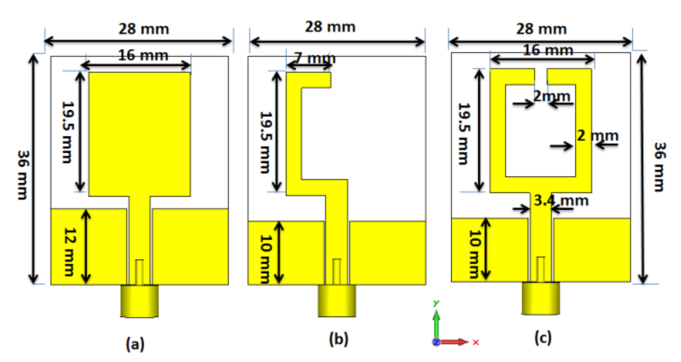
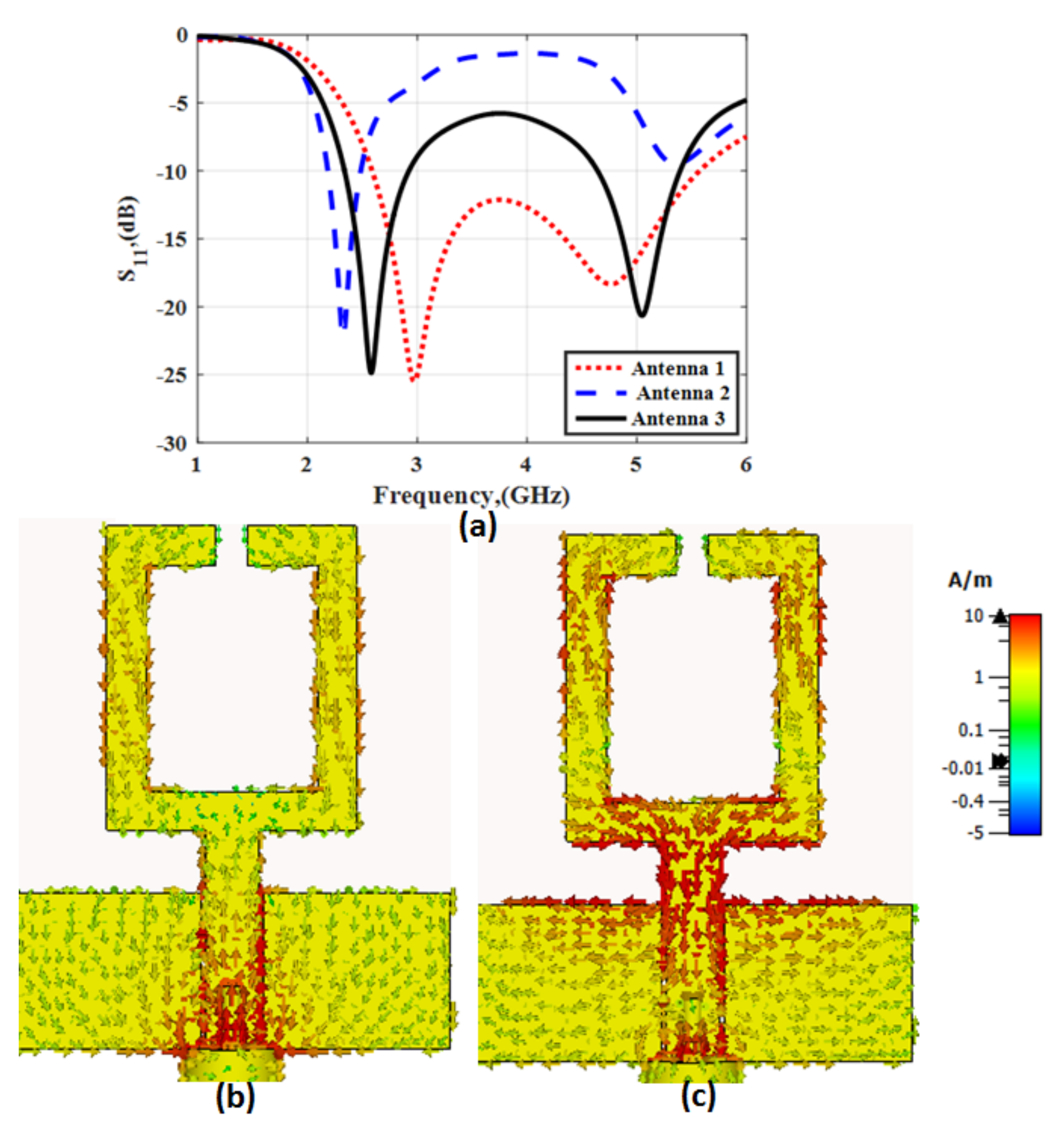
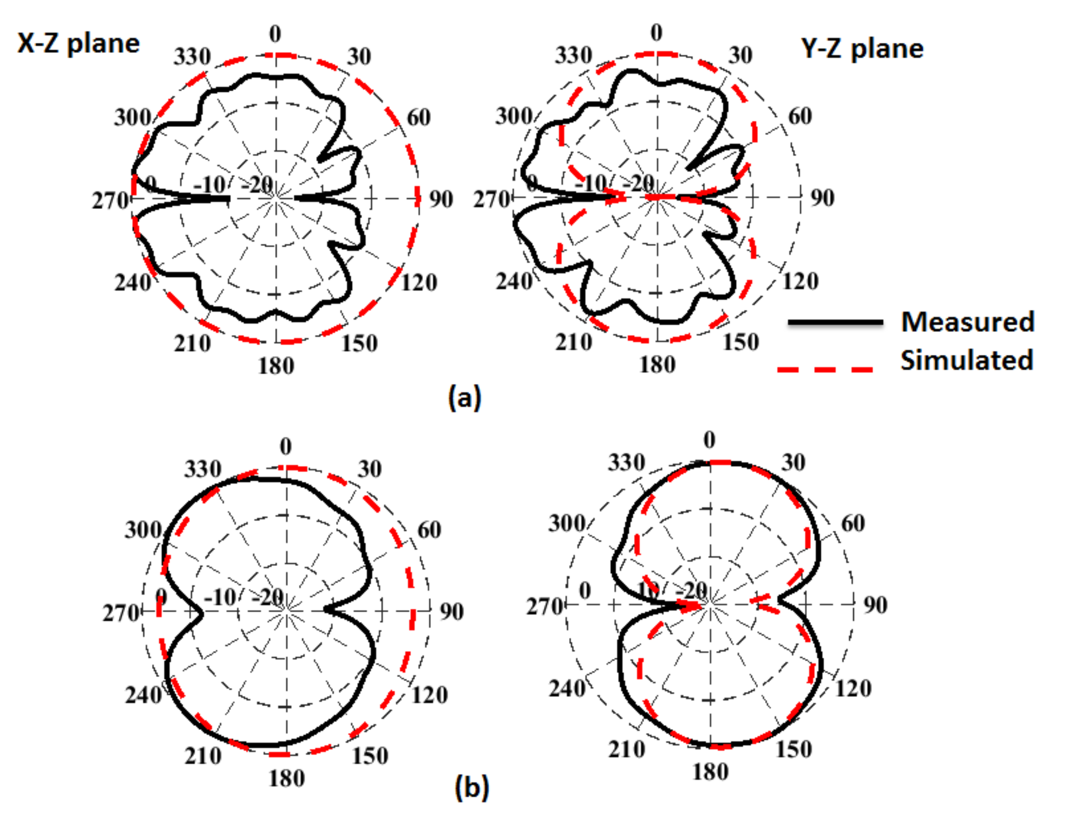
2. Dual-Band Monopole Antenna Structure

Figure 1 shows the development of the proposed dual-band antenna. The three configurations are fed with a coplanar waveguide (CPW-fed) with a transmission width of 3.4 mm and a 0.2 mm gap between the transmission line and ground plane to achieve the proposed 50 Ω of impedance. The total size of all configurations is 28 mm × 36 mm. The simulated S11 results of all configurations are illustrated in Figure 2.
In the case of antenna 1, as shown in Figure 1a, the radiator shape is a rectangular patch with a 16 mm × 19.5 mm dimension. The ground plane length affects the operating bandwidth. When the ground plane equals 12 mm, the antenna is operated at a frequency band from 2.5 GHz up to 5.5 GHz as shown in Figure 2 (antenna 1, the red dotted line).
By changing the shape of the radiator to a simple C shape with a 7 mm × 19.5 mm dimension as shown in Figure 1b, a band with an S11 level lower than −20 dB centered at 2.3 GHz with a bandwidth extended (S11 ≤ −10 dB) from 2.1 GHz to 2.52 GHz and a second band around 5.3 GHz with a S11 level that is −10 dB is displayed in Figure 2 (antenna 2, the blue dashed line). Finally, by adding another inversed C shape to compose an open-loop shape as shown in Figure 1c, a proposed dual-band frequency band can be produced as shown in Figure 2 (antenna 3, the solid black line). The first band is centered on 2.6 GHz with a bandwidth (S11 ≤ −10 dB) from 2.3 GHz to 2.9 GHz, while the second band has a center frequency of 5 GHz and a bandwidth (S11 ≤ −10 dB) operating from 4.6–5.4 GHz.
The antenna 3 current distribution results at 2.6 GHz and 5 GHz are shown in Figure 2b,c, respectively. The concentration of the current is around the edges of the vertical arms and feedline, while it concentrates around the bottom horizontal stub, feedline, and the top part of the two vertical sections, which indicates the radiation mechanism of the antenna at the two frequencies.
The equivalent circuit of antenna 3 (proposed antenna) with the simplified model is shown in Figure 3b. The SMA with the CPW-fed system is modeled with L1, R1, and C1. Two parallel RLC circuits are used to produce the first and second resonance of the dual-band CPW monopole antenna [26,27]. The antenna was fabricated and the proposed shape was printed on FR4 substrate with 4.4 and 1.5 mm for the dielectric constant and thickness, respectively. The fabricated prototype photo with an SMA connector is illustrated in Figure 3c. The antenna was tested using a vector network analyzer (VNA R&S ZVB 20) as shown in Figure 4. The S11 results of the simulated, equivalent circuit, and tested results are displayed in Figure 4. The simulated results show that the antenna is operating at two bands centered on 2.6 GHz and 5 GHz with bandwidth calculated at S11 ≤ −10 dB and extending from 2.3 GHz to 2.9 GHz and 4.6 GHz to 5.4 GHz for the first and the second band, respectively. The equivalent circuit results have the same frequency bands as the simulated results, as shown in Figure 4 (blue and dotted curve). The tested results illustrate that the antenna works at two bands centered on 2.7 GHz and 4.8 GHz with bandwidths within 2.4 GHz to 3.3 GHz and 4.36 GHz to 5.15 GHz for both the first and second band. The tested and simulated results match well, with a small shift between the two results. This is because of the fabrication stage and the soldering effect which cannot be avoided.
The radiation patterns for the simulated and measured results (normalized) in both the x-z and y-z planes at 2.45 GHz and 4.8 GHz are illustrated in Figure 5. The antenna was tested inside an anechoic chamber as displayed in Figure 6. It is seen that the antenna achieves a semi-omnidirectional pattern in the x-z plane and a bidirectional one in the y-z plane. Moreover, the two results have the same trend, which confirms the performance of the antenna. Figure 6 shows the simulated and tested peak gain of the antenna. The antenna has simulated peak gain of around 1.8 dBi and 3.5 dBi at the operating two bands, while it has tested peak gain around 1.5 dBi and 3 dBi for both bands.

3. Proposed Antenna with AMC Structures
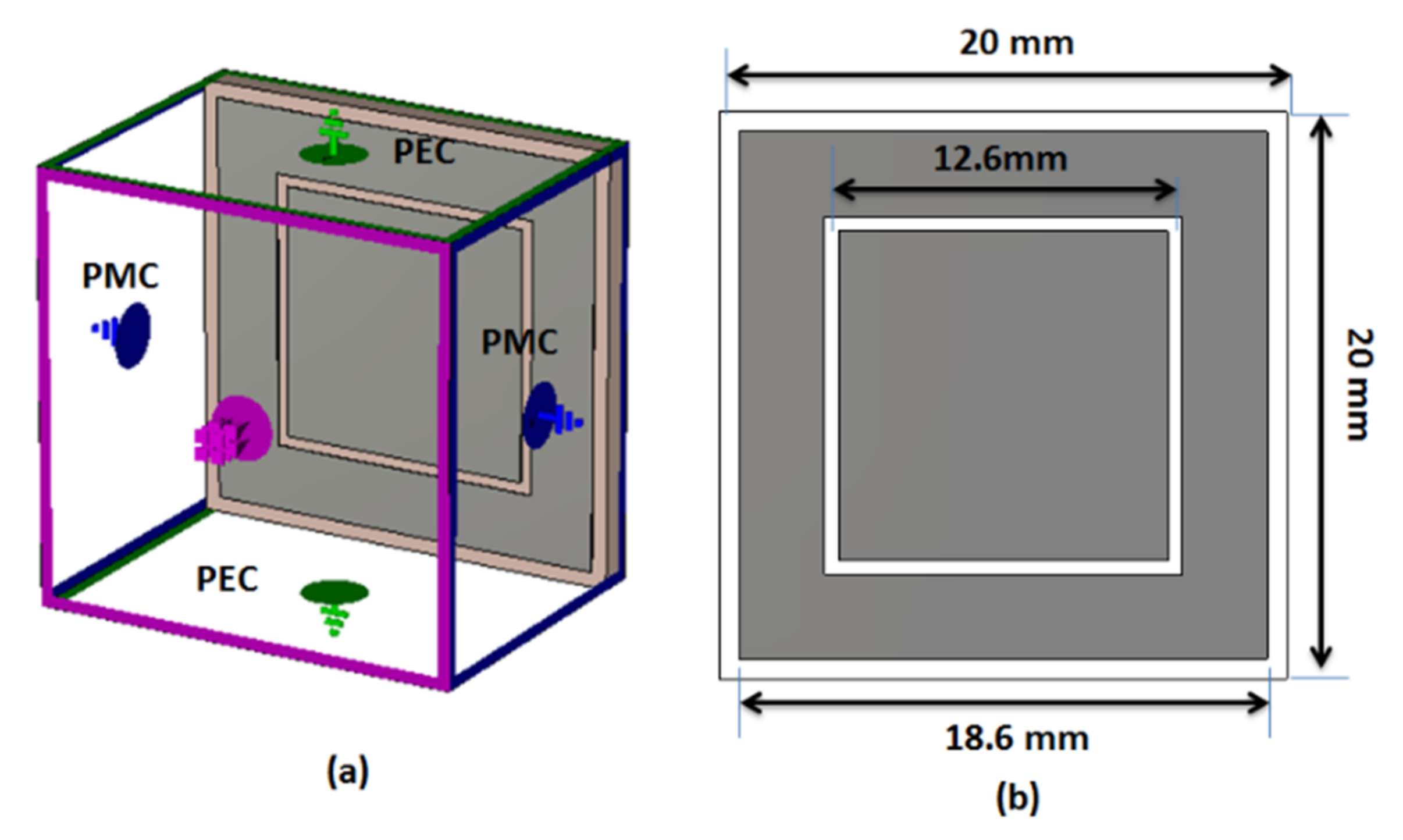
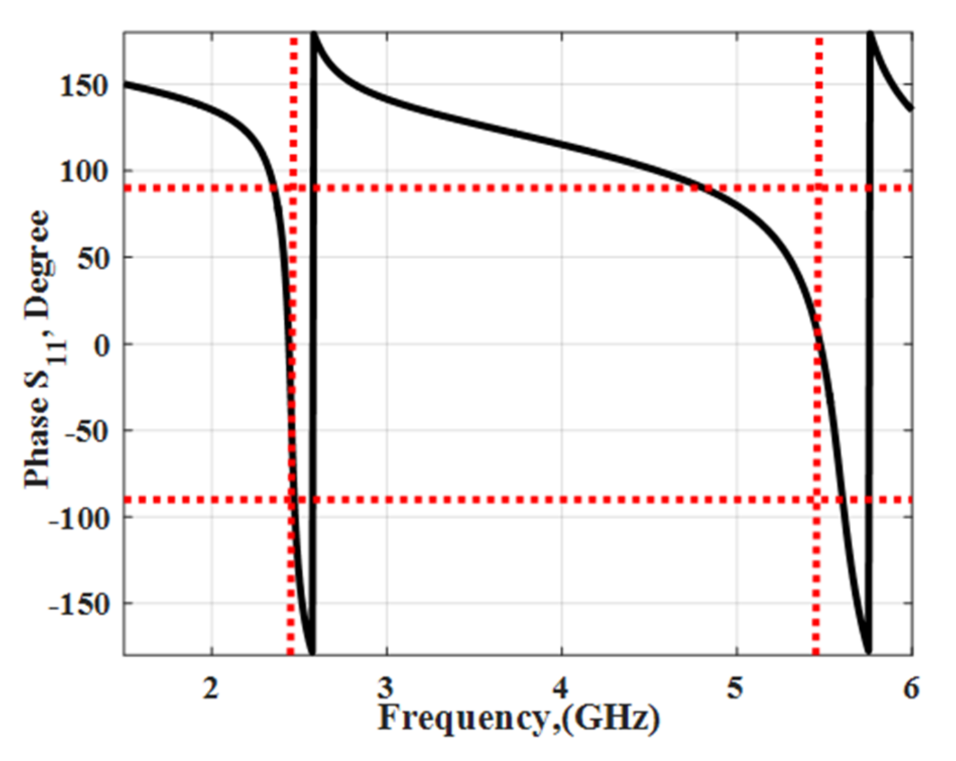
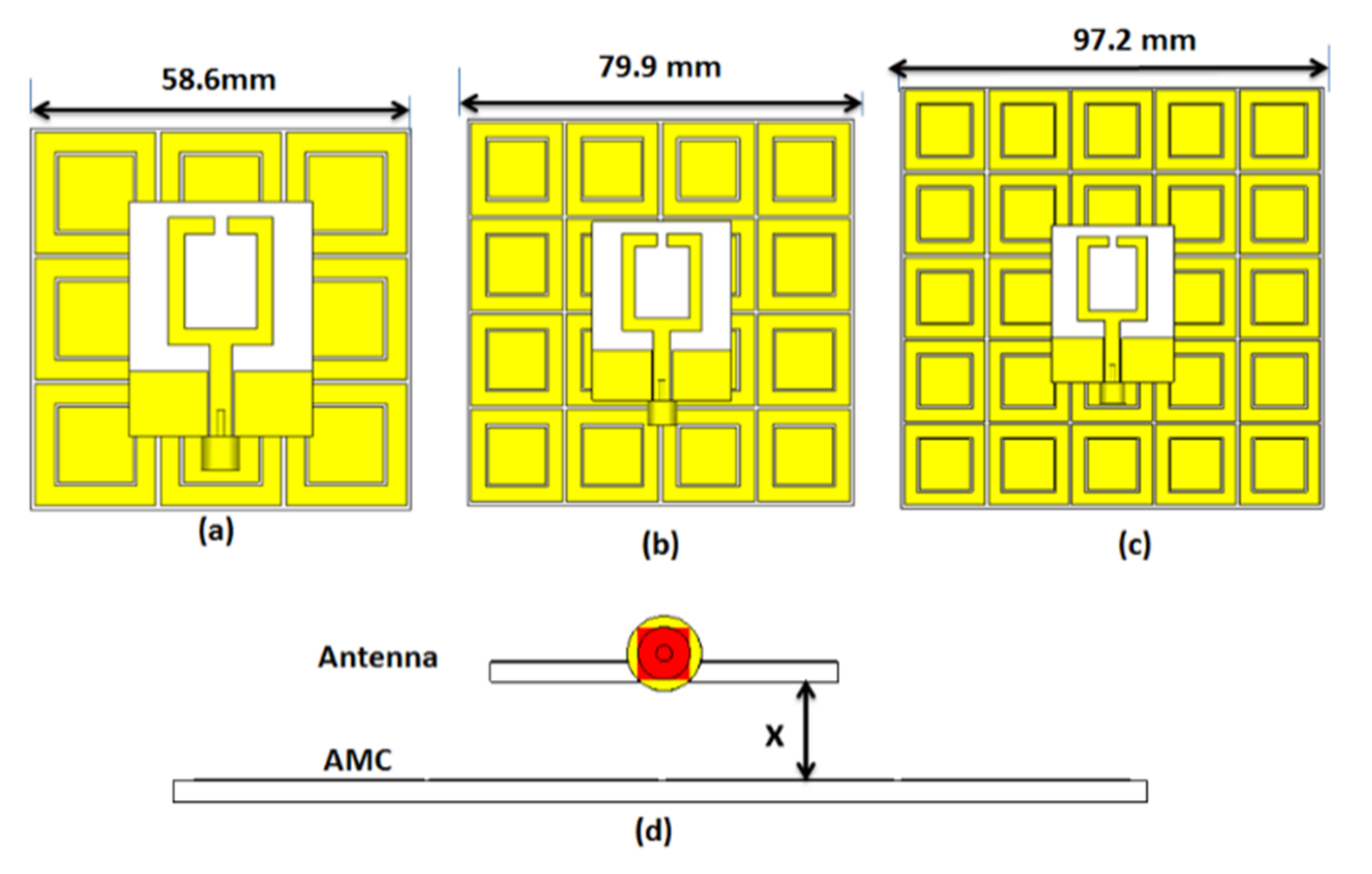
This section introduces the design of the AMC cells and the performance of the antenna in terms of the reflection coefficient, gain, and radiation patterns when in the presence of an AMC-backed array.

3.1. AMC Structure

The 2-D and 3-D layouts of the dual bands AMC unit cell are displayed in Figure 7. It is composed of a slotted outer patch and an inner patch on the top and ground on the bottom of the cell. The optimized dimensions of the unit cell are shown in Figure 7b, while the utilized boundary condition is shown in Figure 7a. The two frequency bands are controlled by changing the dimensions of the unit cell which changes the inductance/capacitance of the structure. The same previous substrate is used in the design. Figure 8 illustrates the reflection phase of the unit cell. It is seen that the reflection achieves a 0° phase at 2.45 GHz, 5.4 GHz, +90° at 2.34 GHz, and 4.7 GHz, while a −90° phase is achieved at 2.48 GHz and 5.6 GHz (the operating band of the AMC). Figure 9 shows the distribution of the surface current at 2.45 GHz and 4.8 GHz to know the mechanism of operation. It is noted that the current is concentrated around the outer patch for the first band and around the inner patch for the second band.

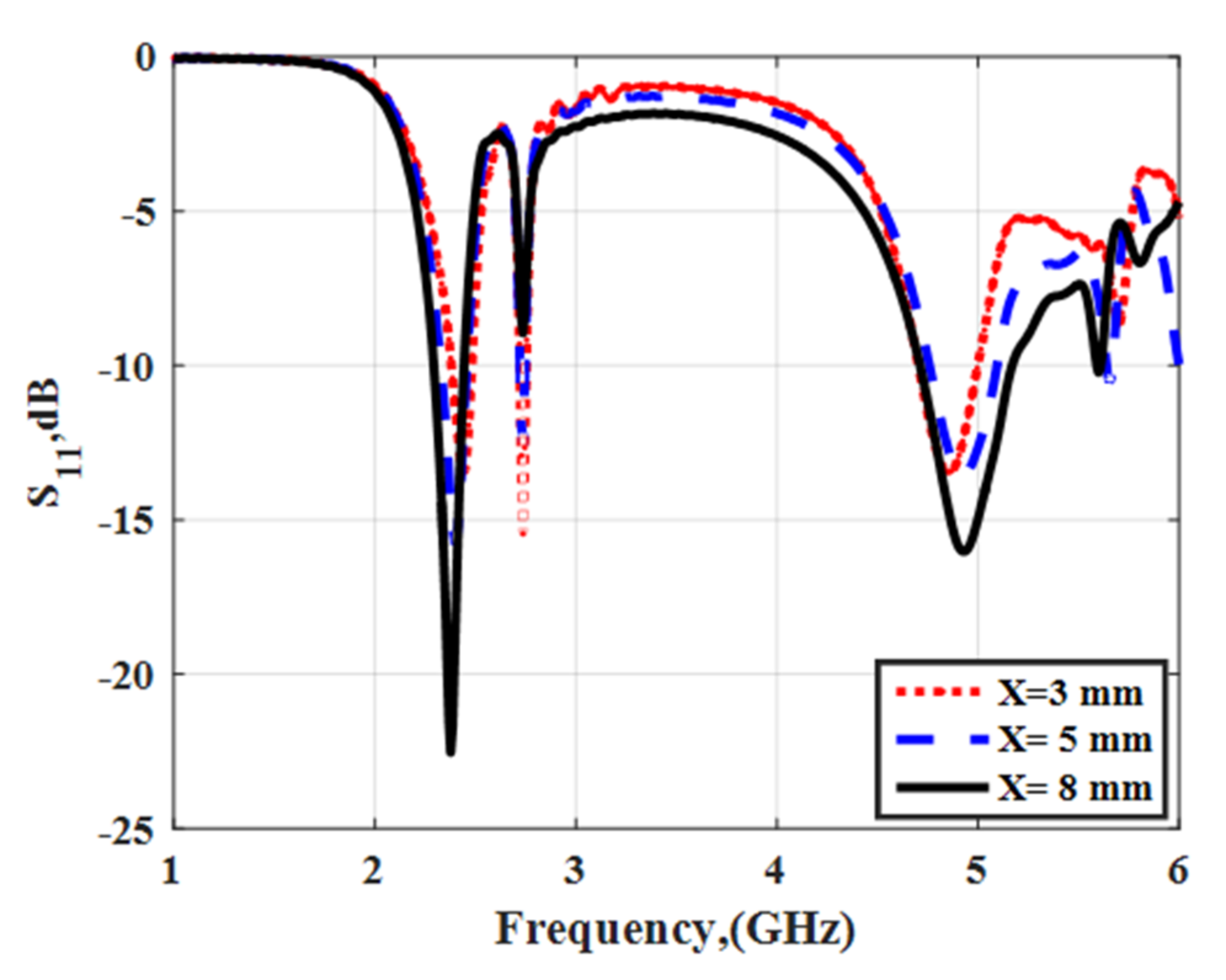
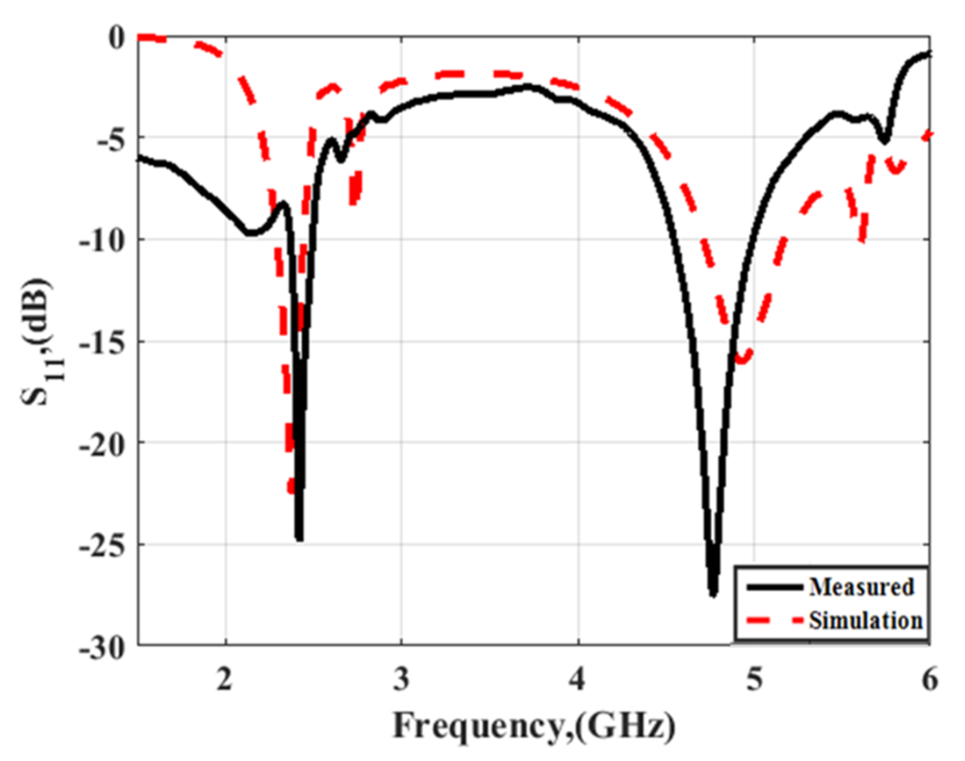
3.2. Proposed Antenna with AMC Integration

The CPW-fed dual-band antenna discussed in the previous section was backed with AMC cells and placed at a distance (X) from the antenna as illustrated in Figure 10. Parametric studies as a function of the array size and array separation (X) were investigated. The effects of cell sizes of 3 × 3, 4 × 4, and 5 × 5 with a distance X = 8 mm on the reflection coefficient and the gain were studied. It was seen that by increasing the array size, the impedance matching in both bands was improved, while a second resonance around 2.7 GHz appeared as shown in Figure 11. Table 1 shows the effect of the cell size on the antenna gain. The gain of the proposed antenna with the AMC is increased with increasing the cell size. It increases by around 1 dBi in both bands by increasing the cell size from 3 × 3 to 5 × 5. The optimized cell size was chosen to be 4 × 4. This cell size achieved a good reflection coefficient and suitable gain at both bands.
The effect of the cell separation (X) at a cell size of 4 × 4 on the reflection coefficient and the gain are investigated. The impedance matching in both bands is affected by increasing the cell separation as shown in Figure 12. Table 2 shows the effect of the cell separation (X) on the antenna gain. The gain of the proposed antenna with AMC has nearly constant values with increasing cell separation. Finally, the optimized cell size was chosen to be 4 × 4 with X = 8 mm (lower than λ0/4 at 2.45 GHz).
The suggested antenna with AMC was fabricated and tested. An 8 mm layer of polystyrene where εr = 1.03 was utilized for separation between the antenna and AMC cell. Figure 13a shows the fabricated prototype of AMC cells and Figure 13b illustrates the proposed antenna integrated with the AMC structures.
The S11 simulated and tested results are shown in Figure 14. The simulated results were gathered for both bands, where the first one has a center frequency of 2.38 and bandwidth from 2.29 GHz to 2.45 GHz and the second has a center frequency of 4.93 GHz and bandwidth from 4.6 GHz to 5.2 GHz. While the first band from the tested results has a center frequency of 2.41 GHz and bandwidth from 2.37–2.5 GHz, the second one has a center frequency of 4.7 GHz and bandwidth from 4.5 GHz to 4.99 GHz. From Figure 14, it is obvious that there is a shift between the two results. This is because many factors, such as the small shift introduced by the antenna without the AMC, as discussed in the previous section, can be a source of error, in addition to the fabrication process and human error introduced by misalignment between the antenna and AMC.
Although there were shifts between the two results, the tested results were achieved the proposed frequency bands. The integrated antenna was tested inside an anechoic chamber as shown in Figure 13c in order to measure the radiation patterns. The simulated and tested normalized results of the radiation pattern at 2.45 GHz and 4.8 GHz in both the x-z and y-z planes are shown in Figure 15. The patterns feature directed beams with reduction in the back loop which was introduced in the antenna without the AMC. Also, good trends between the two results were achieved. The tested peak gain values of the integrated antenna were 5 dBi and 7.5 dBi at 2.45 GHz and 4.8 GHz, respectively, with a small deviation between the simulated results. As well, the peak gain of the integrated antenna was around 4.5 dBi more than the antenna without the AMC. Finally, from the previous results, it is obvious that the integrated antenna can be used in sub-6 GHz applications. To validate the novelty of the design, the suggested design is compared with other works as tabulated in Table 3. It is seen that the suggested antenna has good performance with a compact size, which makes it the suggested design to be used in dual-band wireless applications.

4. Conclusions

Dual-band monopole antennas integrated with an AMC reflector have been simulated, fabricated, and tested here. A dual-band AMC array structure has been utilized and placed under the antenna to improve the standalone antenna gain. The suggested integrated antenna has a miniaturized size of (0.63λ0 × 0.63λ0 × 0.064λ0 at 2.4 GHz). The tested results have been compared with the simulated results with a reasonable trend between them to confirm the performance of the antenna. The tested results of the integrated model have been cheeked using VNA, which confirmed that the antenna operated at two bands, where S11 ≤ −10 dB from 2.37 GHz to 2.5 GHz and from 4.45 GHz to 4.9 GHz. Also, peak gain values of 5 dBi and 7.5 dBi for were achieved for both bands, respectively, which makes them suggested models for utilization in sub-6 GHz 5G indoor and outdoor applications.

Author Contributions

Conceptualization, M.A.A. and A.A.I.; methodology, A.A.I.; software, A.A.I.; validation, A.D., M.A.A. and M.F.A.S.; investigation, A.A.I. fabrication, and measurements, M.F.A.S.; writing—original draft preparation, A.A.I.; writing—review and editing, A.D., M.F.A.S. and M.A.A. All authors have read and agreed to the published version of the manuscript.

Funding

This research was funded by the Deputyship for Research &Innovation, Ministry of Education in Saudi Arabia grant number IF-PSAU-2021/01/18062. And the APC was funded by the Deputyship for Research &Innovation, Ministry of Education in Saudi Arabia through the project number (IF-PSAU-2021/01/18062).

Data Availability Statement

All data generated or analyzed during this study are included in this article.

Acknowledgments

The authors extend their appreciation to the Deputyship for Research &Innovation, Ministry of Education in Saudi Arabia for funding this research work through the project number (IF-PSAU-2021/01/18062).

Conflicts of Interest

The authors declare no conflict of interest.

References

  1. Shafi, M.; Molisch, A.F.; Smith, P.J.; Haustein, T.; Zhu, P.; De Silva, P.; Tufvesson, F.; Benjebbour, A.; Wunder, G. 5G: A tutorial overview of standards, trials, challenges, deployment, and practice. IEEE J. Sel. Areas Commun. 2017, 35, 1201–1221. [Google Scholar] [CrossRef]
  2. Andrews, J.G.; Buzzi, S.; Choi, W.; Hanly, S.V.; Lozano, A.; Soong, A.C.; Zhang, J.C. What Will 5G Be? IEEE J. Sel. Areas Commun. 2014, 32, 1065–1082. [Google Scholar] [CrossRef]
  3. Liu, Q.; Liu, H.; He, W.; He, S. A low-profile dual-band dual-polarized antenna with an AMC reflector for 5G communications. IEEE Access 2020, 8, 24072–24080. [Google Scholar] [CrossRef]
  4. Aboualalaa, M. Dual-band Co-planar Waveguide Slot Antenna for 5G sub-6 GHz Applications. In Proceedings of the IEEE MTT-S International Conference on Numerical Electromagnetic and Multiphysics Modeling and Optimization (NEMO), Hangzhou, China, 7–9 December 2020; pp. 1–4. [Google Scholar]
  5. Ikram, M.; Al Abbas, E.; Nguyen-Trong, N.; Sayidmarie, K.H.; Abbosh, A. Integrated frequency-reconfigurable slot antenna and connected slot antenna array for 4G and 5G mobile handsets. IEEE Trans. Antennas Propag. 2019, 67, 7225–7233. [Google Scholar] [CrossRef]
  6. Alieldin, A.; Huang, Y.; Boyes, S.J.; Stanley, M.; Joseph, S.D.; Hua, Q.; Lei, D. A triple-band dual-polarized indoor base station antenna for 2G, 3G, 4G and sub-6 GHz 5G applications. IEEE Access 2018, 6, 49209–49216. [Google Scholar] [CrossRef]
  7. Sharawi, M.S.; Ikram, M.; Shamim, A. A two concentric slot loop based connected array MIMO antenna system for 4G/5G terminals. IEEE Trans. Antennas Propag. 2017, 65, 6679–6686. [Google Scholar] [CrossRef] [Green Version]
  8. Hua, Q.; Huang, Y.; Song, C.; Akinsolu, M.O.; Liu, B.; Jia, T.; Xu, Q.; Alieldin, A. A novel compact quadruple-band indoor base station antenna for 2G/3G/4G/5G Systems. IEEE Access 2019, 7, 151350–151358. [Google Scholar] [CrossRef]
  9. Liu, Y.; Wang, S.; Li, N.; Wang, J.-B.; Zhao, J. A compact dual-band dual-polarized antenna with filtering structures for sub-6 GHz base station applications. IEEE Antennas Wirel. Propag. Lett. 2018, 17, 1764–1768. [Google Scholar] [CrossRef]
  10. Li, X.; Zhu, H.; Huang, Z. A CPW-Fed Miniaturized Dual-Band Antenna for 5G Applications. In Proceedings of the 2020 IEEE MTT-S International Conference on Numerical Electromagnetic and Multiphysics Modeling and Optimization (NEMO), Hangzhou, China, 7–9 December 2020; pp. 1–3. [Google Scholar]
  11. Saini, R.K.; Dwari, S.; Mandal, M.K. CPW-fed dual-band dual-sense circularly polarized monopole antenna. IEEE Antennas Wirel. Propag. Lett. 2017, 16, 2497–2500. [Google Scholar] [CrossRef]
  12. Liang, W.; Jiao, Y.-C.; Luan, Y.; Tian, C. A dual-band circularly polarized complementary antenna. IEEE Antennas Wirel. Propag. Lett. 2015, 14, 1153–1156. [Google Scholar] [CrossRef]
  13. Sarkar, S.; Gupta, B. A dual-band circularly polarized antenna with a dual-band amc reflector for RFID readers. IEEE Antennas Wirel. Propag. Lett. 2020, 19, 796–800. [Google Scholar] [CrossRef]
  14. Paracha, K.N.; Rahim, S.K.A.; Soh, P.J.; Kamarudin, M.R.; Tan, K.G.; Lo, Y.C.; Islam, M.T. A low profile, dual-band, dual-polarized antenna for indoor/outdoor wearable application. IEEE Access 2019, 7, 33277–33288. [Google Scholar] [CrossRef]
  15. Saad, A.A.R.; Ibrahim, A.A.; Haraz, O.M.; Elboushi, A. Tri-band compact ACS-fed meander-line antenna for wireless communications. Int. J. Microw. Wirel. Technol. 2017, 9, 1895–1903. [Google Scholar] [CrossRef]
  16. Ijiguchi, T.; Kanemoto, D.; Yoshitomi, K.; Yoshida, K.; Ishikawa, A.; Fukagawa, S.; Kodama, N.; Tahira, A.; Kanaya, H. Circularly polarized one-sided directional slot antenna with reflector metal for 5.8-GHz DSRC operations. IEEE Antennas Wirel. Propag. Lett. 2014, 13, 778–781. [Google Scholar] [CrossRef]
  17. Zhang, Q.; Gao, Y. A compact broadband dual-polarized antenna array for base stations. IEEE Antennas Wirel. Propag. Lett. 2018, 17, 1073–1076. [Google Scholar] [CrossRef]
  18. Wu, J.; Yang, S.; Chen, Y.; Qu, S.; Nie, Z. A low profile dual-polarized wideband omnidirectional antenna based on AMC reflector. IEEE Trans. Antennas Propag. 2016, 65, 368–374. [Google Scholar] [CrossRef]
  19. Ameen, M.; Chaudhary, R. Metamaterial-based wideband circularly polarised antenna with rotated V-shaped metasurface for small satellite applications. Electron. Lett. 2019, 55, 365–366. [Google Scholar] [CrossRef]
  20. Gong, Y.; Yang, S.; Li, B.; Chen, Y.; Tong, F.; Yu, C. Multi-Band and High Gain Antenna Using AMC Ground Characterized with Four Zero-Phases of Reflection Coefficient. IEEE Access 2020, 8, 171457–171468. [Google Scholar] [CrossRef]
  21. Yan, S.; Soh, P.J.; Vandenbosch, G.A.E. Low-profile dual-band textile antenna with artificial magnetic conductor plane. IEEE Trans. Antennas Propag. 2014, 62, 6487–6490. [Google Scholar] [CrossRef]
  22. Malekpoor, H.; Jam, S. Improved radiation performance of low profile printed slot antenna using wideband planar AMC surface. IEEE Trans. Antennas Propag. 2016, 64, 4626–4638. [Google Scholar] [CrossRef]
  23. Tran, H.H.; Park, I. A dual-wideband circularly polarized antenna using an artificial magnetic conductor. IEEE Antennas Wirel. Propag. Lett. 2015, 15, 950–953. [Google Scholar]
  24. Ibrahim, A.A.; Ali, W.A. High gain, wideband and low mutual coupling AMC-based millimeter wave MIMO antenna for 5G NR networks. AEU-Int. J. Electron. Commun. 2021, 142, 153990. [Google Scholar] [CrossRef]
  25. Hamadi, H.B.; Ghnimi, S.; Latrach, L.; Gharsallah, A. Design of the millimeter-wave textile antenna loaded with AMC structures for 5G applications. In Proceedings of the 2020 32nd International Conference on Microelectronics (ICM), Aqaba, Jordan, 14–17 December 2020; pp. 1–5. [Google Scholar]
  26. Saraswat, K.; Harish, A.R. Flexible dual-band dual-polarized CPW-fed monopole antenna with discrete-frequency reconfigurability. IET Microw. Antennas Propag. 2019, 13, 2053–2060. [Google Scholar] [CrossRef]
  27. Al-Zayed, A.S.; Shameena, V.A. Planar dual-band monopole antenna with an extended ground plane for WLAN applications. Int. J. Antennas Propag. 2016, 2016, 6798960. [Google Scholar] [CrossRef] [Green Version]
Figure 1. CPW monopole antenna structure development: (a) Antenna 1 (b); antenna 2; (c) antenna 3.
Electronics 11 02211 g001
Figure 2. The CPW monopole antennas: (a) Simulated S11 results; (b) antenna 3 current distribution at 2.6 GHz; (c) antenna 3 current distribution at 5 GHz.
Electronics 11 02211 g002
Figure 3. CPW monopole antenna structure: (a) 2-D configuration; (b) equivalent circuit with the simplified model (where R1 = 3.097 Ω, R2 = 87.13 Ω, R3 = 76.24 Ω, L1 = 1.73 nH, L2 = 1.486 nH, L3 = 0.793 nH, C1 = 0.05 pF, C2 = 3.22 pF, C3 = 1.59 pF); (c) fabricated prototype.
Electronics 11 02211 g003
Figure 4. The CPW dual−band monopole antenna: (a) Simulated, equivalent circuit, and measured S11 results; (b) measured S11 results with VNA.
Electronics 11 02211 g004
Figure 5. Normalized radiation pattern results of the CPW dual−band monopole antenna (a) at 2.45 GHz and (b) at 4.8 GHz.
Electronics 11 02211 g005
Figure 6. The CPW dual-band monopole antenna: (a) Peak gain results; (b) radiation pattern measurement setup.
Electronics 11 02211 g006
Figure 7. AMC structure (a) with boundary conditions and the (b) 2-D configuration.
Electronics 11 02211 g007
Figure 8. The phase of S11 results in AMC structure.
Electronics 11 02211 g008
Figure 9. Current distribution of AMC structure (a) at 2.45 GHz and (b) at 4.8 GHz.
Electronics 11 02211 g009
Figure 10. Proposed antenna with AMC with different integration sizes: (a) 3 × 3; (b) 4 × 4; (c) 5 × 5; (d) top view.
Electronics 11 02211 g010
Figure 11. Simulated S11 results of the proposed antenna with different AMC structure sizes.
Electronics 11 02211 g011
Figure 12. Simulated S11 results of the proposed antenna with different space lengths (X) away from the antenna.
Electronics 11 02211 g012
Figure 13. The layout of the proposed CPW monopole antenna. (a) Fabricated AMC prototype structure. (b) Fabricated prototype of antenna integrated with the AMC. (c) Radiation pattern measurement setup of the proposed antenna.
Electronics 11 02211 g013
Figure 14. S11 results of the proposed antenna integrated with AMC.
Electronics 11 02211 g014
Figure 15. Normalized radiation pattern results of antenna integrated with AMC (a) at 2.45 GHz and (b) at 4.8 GHz.
Electronics 11 02211 g015
Table 1. The effect of the cell size on the antenna gain.
Array SizeGain (dBi)
2.45 GHz4.8 GHz
3 × 36.48.5
4 × 46.59.4
5 × 579.24
Table 2. The effect of the cell separation (X) on the antenna gain.
Cell Separation (X), (mm)Gain (dBi)
2.45 GHz4.8 GHz
X = 36.58.7
X = 56.59.4
X = 86.59.4
Table 3. The suggested design versus other published designs.
ReferenceAMC Size
(mm202)
εr/Thickness (mm)Frequency Bands
(GHz)
No. of AMC BandsAMC Space from
Antenna
(mm)
Peak Gain
(dBi)
[3]79.6 × 79.6
0.83 × 0.83
4.4/13.14–3.83/4.40–5.02277.1/8.2
[13]210 × 210
0.63 × 0.63
4.4/1.520.90–0.93/2.43–2.472303.1/6.2
[14]130 × 130
0.67 × 0.67
3/3.041.56–1.59/2.43–2.45210.55.1/5.08
[18]200 × 200
1.13 × 1.13
4.4/1.61.7–2.7117.75
[19]45 × 45
0.32 × 0.32
4.4/1.62.18–3.041175.76
[20]90 × 90
0.63 × 0.63
4.4/1.62.13–2.87/3.22–4.75/5.54–5.864238.05/10.77/7.87
[21]100 × 100
0.73 × 0.73
1.2/1.52.2–2.5, 5.03–5.8621.54
[22]50 × 80
0.95 × 1.53
4.4/2.45.75–14.511410.65
[23]72 × 72
0.48 × 0.48
2.2/0.52–3, 3.8–6.32176.6/7.4
This work0.63 × 0.634.4/1.62.37–2.5/4.45–4.9285/7.5
Publisher’s Note: MDPI stays neutral with regard to jurisdictional claims in published maps and institutional affiliations.

