Abstract
In this work, a feasibility study for lung lesion detection through microwave imaging based on Huygens’ principle (HP) has been performed using multilayer oval shaped phantoms mimicking human torso having a cylindrically shaped inclusion simulating lung lesion. First, validation of the proposed imaging method has been performed through phantom experiments using a dedicated realistic human torso model inside an anechoic chamber, employing a frequency range of 1–5 GHz. Subsequently, the miniaturized torso phantom validation (using both single and double inclusion scenarios) has been accomplished using a microwave imaging (MWI) device, which operates in free space using two antennas in multi-bistatic configuration. The identification of the target’s presence in the lung layer has been achieved on the obtained images after applying both of the following artifact removal procedures: (i) the “rotation subtraction” method using two adjacent transmitting antenna positions, and (ii) the “ideal” artifact removal procedure utilizing the difference between received signals from unhealthy and healthy scenarios. In addition, a quantitative analysis of the obtained images was executed based on the definition of signal to clutter ratio (SCR). The obtained results verify that HP can be utilized successfully to discover the presence and location of the inclusion in the lung-mimicking phantom, achieving an SCR of 9.88 dB.
1. Introduction
Lung damage is one of the pervasive diseases of the respiratory system which can be representative of the presence of lung lesions such as lung cancer, tumors, or lung infection (COVID-19). Nowadays, among the various lung lesions, COVID-19 infection is one of the most prevalent problems that plays a prominent role in millions of deaths. Early detection of lung lesions can be an effective way to prevent lung damage, prevent further spread of lung infection, especially in the case of COVID-19, and leads to a reduction in the mortality rate of pulmonary patients. Currently, images taken by computed tomography (CT) scan and X-ray devices are considered as a reliable detection reference for revealing lung lesions inside the patient’s body and for monitoring the treatment procedure. However, exposing the patients to ionizing radiation, which is used in both techniques, is a major concern [1,2]. Therefore, a lot of research and efforts are performed with the purpose of achieving novel, safe, and rapid diagnosis methods for lung lesion detection, particularly, coronavirus detection.
Nowadays, microwave imaging techniques have been known as safe and attractive tools that can be used for diagnostic purposes due to their capability to safely generate an image of the human body [3]. The significant difference in dielectric property values between unhealthy tissues and healthy surrounding tissues is the basis of the microwave imaging technique [4]. In the past few decades, the attention of various research teams has been significantly raised to microwave imaging techniques for breast cancer detection [4], bone imaging [5,6], brain stroke classification, and lung cancer detection [7,8,9,10]. For instance, a three-dimensional electromagnetic torso scanner, which operates in the 0.83 to 1.9 GHz range, has been introduced in [9]. In addition, according to studies in [9,10] the conductivity and permittivity values of cancerous tissues are twice and three times higher than healthy tissues, respectively. Since the ground-glass opacities formed inside the lungs due to lung lesion indicate a dielectric properties contrast between infected lung tissues and the normal tissues surrounding them [11], microwave imaging techniques have the potential to be successful in diagnosing the lung lesion. In [12], the authors performed a review of the existing COVID-19 detection techniques based on microwaves, concluding that microwave imaging is promising as long as current limitations in image processing and antenna design are appropriately addressed.
Recently, a preliminary investigation on lung infection detection through microwave imaging using the Huygens principle (HP) has been performed via measurements in an anechoic chamber using two antennas in free space [13,14]. According to the HP, “each locus of a wave excites the local matter which reradiates a secondary wavelet, and all wavelets superpose to a new, resulting wave (the envelope of those wavelets), and so on” [15]. When applying the HP to forward-propagate the waves, there is no need to solve inverse problems. Together with its simplicity, this methodology permits the capture of the dielectric contrast [14]. The “rotation subtraction” artifact removal method has been applied as a signal pre-processing method with the aim of eliminating the artifacts and achieving detection [13].
The paper’s goal is to investigate the potential of HP-based microwave imaging techniques for detecting lung lesions. Specifically, lung lesion detection, through microwave imaging technique, will be investigated via phantom experiments both inside the anechoic chamber and using an MWI device named MammoWave (UBT Srl, Assisi, Italy) which was initiated originally for breast imaging [16]. For this purpose, a multilayer oval shaped realistic phantom mimicking a human torso having a cylindrically shaped inclusion simulating a lung lesion was fabricated. First, the realistic torso phantom was used to perform frequency-domain measurements inside an anechoic chamber using VNA to record the transfer function (S21) employing two microstrip antennas operating in 1 to 5 GHz (optimal frequency for lung imaging [9,10,17]) using 5 MHz frequency sampling, in a multi-bistatic way. Then, the experiment was repeated using the torso phantom without the lesion layer which is known as the “healthy” scenario.
Images have been obtained by applying the HP-imaging procedure. To reconstruct the image, an artifact removal method which we refer to as “rotation subtraction” was carried out using two slightly displaced transmitting positions. Next, an “ideal” method for artifact removal, employing the subtraction between received data from the unhealthy and data of the healthy torso phantom, was applied. We have verified that both artifact removal techniques permit detection.
In the next stage, the miniaturized torso phantom was fabricated to perform the phantom experiments using the MammoWave device, investigating different scenarios. Next, the same imaging algorithm (HP-based imaging algorithm) was applied to generate the images.
The remainder of this paper is divided into three sections as follows: the phantom descriptions, the experimental configuration for phantom measurements using the two proposed approaches, the imaging procedure, and the image quantification are presented in Section 2. Subsequently, Section 3 details all the results and discussions. Finally, Section 4 concludes the paper.
2. Experimental Configuration
2.1. Phantom Fabrication
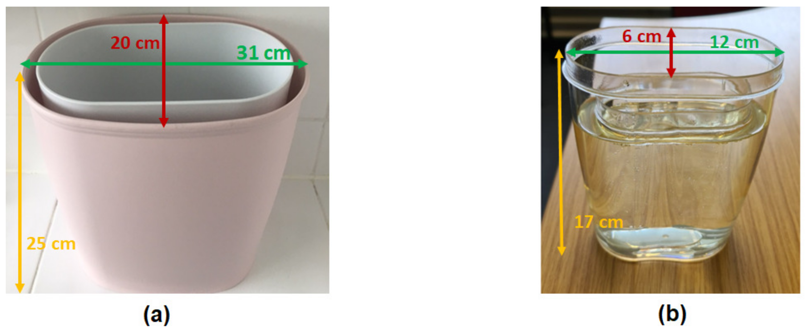
In this research, a multilayer phantom that mimics the human torso in terms of dielectric properties and geometrics, has been constructed to be used for our MWI experiments employing frequency range from 1 GHz to 5 GHz [9]. The torso phantom has been fabricated using two concentric elliptically shaped layers; in more details: (i) an external layer with axes of 31 cm and 20 cm, and height of 25 cm has been filled with a liquid dielectrically mimicking a combination of muscle, fat, and rib bone tissues; (ii) an internal layer with the axes of 27 cm and 14 cm, and height of 25 cm has been filled with a liquid dielectrically mimicking lung (inflated) tissue. A 15 mL tube in a cylindrical shape is positioned inside the internal layer, to mimic the lung lesion. This realistic phantom has been designed to mimic a torso with a small-size chest circumference (82 cm) with the aim of performing measurements inside an anechoic chamber. The dielectric properties of the tissues to be mimicked are derived from [18,19] and are shown in Table 1. In this paper, the dielectric properties of the lesion as reported in [11] are used.

Table 1.
Dielectric constant and conductivity at 2 GHz [9,11,18,19].
A kind of oil, named TLe11.5C.045 with dielectric constant value 7 and conductivity value 0.3 S/m, provided by ZMT Zurich MedTech Company [20]), simulated a combination of fat, muscle, and rib bones tissues. A kind of mixture containing 90% glycerol and 15% water posing the dielectric constant of 15 and conductivity of 2 S/m (at 2 GHz) was used to mimic the lung layer [21]. Tap water was used as a lung lesion mimicking material, similarly to [9,11].
A miniaturized model of the torso phantom (having external layer with the axes of 12 cm and 6 cm, and height of 17 cm, and internal layer with the axes of 9.5 cm and 3.5 cm, and height of 16 cm), was also constructed by considering the same tissue-mimicking materials, for performing measurements using MammoWave device. The realistic and the miniaturized fabricated torso phantoms are shown in Figure 1a,b, respectively.

Figure 1.
(a) Fabricated realistic torso phantom used for measurements inside anechoic chamber; (b) the miniaturized torso phantom (here without inclusion) used for MammoWave device’s measurements.
2.2. Measurements Inside the Anechoic Chamber
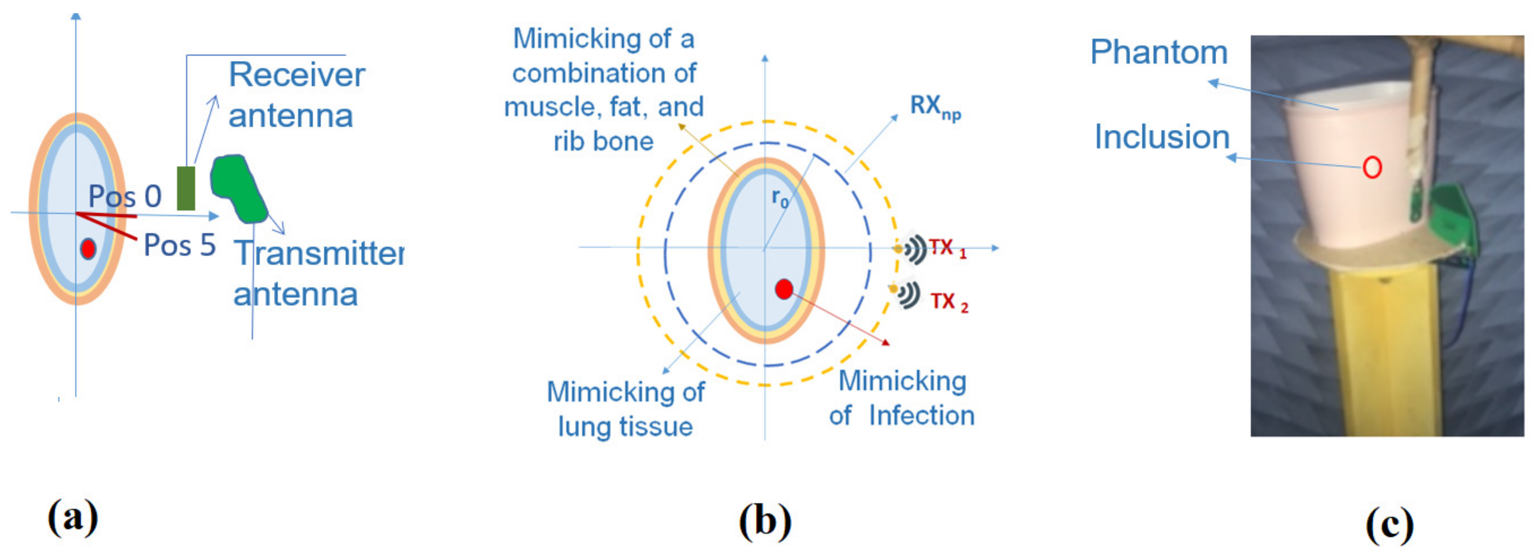
The following equipment have been employed to perform the phantom experiments inside the anechoic chamber: (i) two different UWB antennas (Planar UWB Horn Antenna (310C Next-RF), emfcomp, Chalgrove, UK, used as the transmitter and the PulsON P200 antenna, Fort Worth, TX, USA, used as a receiver which were both placed in the free space), it should be mentioned that the antennas are vertically polarized and omni-directional in the azimuth plane; (ii) a VNA device (model MS2028C, Anritsu, Luton, UK) for recording the transfer function (S21) between the two antennas; (iii) a rotatable table on which the phantom is placed. The transmitting antenna was positioned 30 cm away from the center of the phantom, while the receiving antenna was mounted 25 cm away from the center of the phantom. The experiments were completed by performing measurements using M = 2 transmitting positions separated by from each other (placed at positions and ) which were synthesized by accurately rotating the phantom instead of displacing the transmitting antenna positions. For each transmitting position, the receiver antenna rotated around the phantom and the complex S21 values were recorded over a frequency range of 1–5 GHz, using a frequency sample spacing of 5 MHz, every , which led to a total of = 60 receiving points. Next, the measurement was repeated for the “healthy” phantom (torso phantom without lung lesion layer). The measurement set-up diagram, the pictorial top-view of the multilayered torso phantom, and the position of the phantom with respect to the transmitting position of inside the anechoic chamber are shown in Figure 2a–c, respectively.

Figure 2.
(a) The measurement set-up diagram; (b) pictorial top-view of the multilayered torso phantom; (c) phantom’s position on the center of the rotatable table inside the anechoic chamber. The external and the internal antennas are the transmitter and receiver, respectively.
2.3. Microwave Imaging Device Description
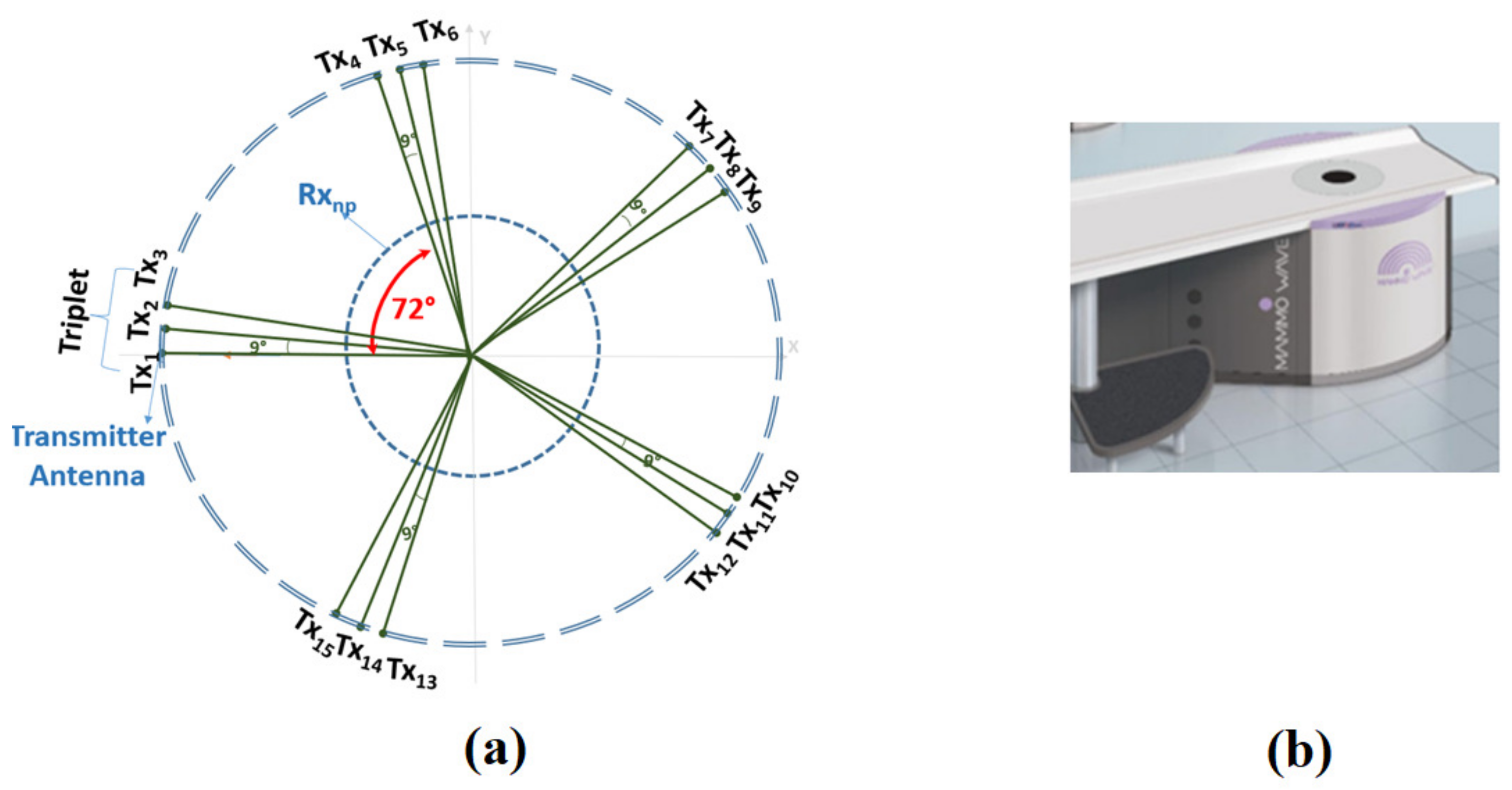
The MammoWave device, which was initially invented for breast imaging, consists of: (i) aluminium cylindrical hub with a radius of approximately 50 cm, which is internally covered by the microwave absorbers and is equipped with a hole and a cup to keep the object to be imaged, (ii) two horn-type and Vivaldi-type antennas employed as the transmitter and receiver, respectively, which are installed at the same height, in free space, and are able to rotate around the azimuth plane. The antennas were connected to a 2-port VNA (S5065, Cobalt series, Copper Mountain, Indianapolis, IN, USA), which operates up to 6.5 GHz [6,16]. The phantom experiments were completed using 15 different transmitting positions (M = 15) displaced in 5 triplets centered at , , , , and . For each transmitting position () the receiver antenna rotated around the phantom and the complex S21 values were recorded over frequencies from of 1 GHz to 6.5 GHz, using a frequency sample spacing of 5 MHz, every , leading to a total of = 80 receiving points, (the transmitting positions are indicated with the index m with m = 1, 2,…, 15 and the receiving positions with the index = 1, 2,…, 80. Figure 3a,b show pictorial views of the MammoWave measurements set-up and the device, respectively.
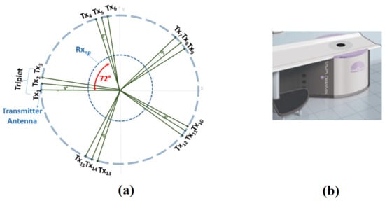
Figure 3.
(a) Pictorial view of the MammoWave measurements set-up; (b) the MammoWave device [16].
2.4. Imaging Procedure Based on Huygens’ Principle
The HP was applied to complex S21 in order to construct the image [22]. As above mentioned, the complex S21 was recorded at points , displaced along a circular surface having radius ; the received signals can be expressed as:
Subscripts m and indicate transmitting points and the receiving positions, where m and vary from 1 to M, and 1 to , respectively. In more details, the field inside the object has been calculated as the superposition of fields radiated by the receiving points of Equation (1):
where the observation point is indicated by , the wave number for the media in the imaging zone and the spatial sampling are demonstrated by and , respectively. The strings “rcst” and “HP” in , represent the reconstructed internal field, and the employed HP-based procedure, respectively. The Green’s function G is used to propagate the field.
For dealing with the artifacts which may happen due to the transmitter image or reflections from the layers, signal pre-processing technique has been utilized to suppress artifacts and achieve accurate detection. For eliminating the artifacts, two different techniques have been applied: (i) the rotation subtraction between two different transmitting points (displaced apart), expressed in Equation (3):
where and belong to the two adjacent transmitting positions, apart, and (ii) the subtraction between the recorded S21 of “healthy” scenario and the “unhealthy” scenario (having the target as the lung lesion) by applying Equation (4):
where and represent the same transmitting position for unhealthy phantom and healthy phantom, respectively. Subsequently, by assumption of having frequencies, intensity of the resulting image (I) can be achieved by summing incoherently all solutions as:
2.5. Image Quantification
It may happen that obtained images include some clutter even after artifact removal procedures. In order to quantify capabilities of image detection or for comparing the performance of the artifact removal methods, the SCR (signal to clutter ratio) that is specified by the ratio between the maximum intensity evaluated in the region of the lesion divided by the maximum intensity outside the region of the lesion has been employed [23].
3. Results and Discussions
In this paper, our aim has been to verify that the HP-based imaging procedure is capable of successfully detecting a lung lesion in phantoms. Earlier, the authors performed investigations to validate HP imaging in cylindrical objects with inclusions [14] and in breast [16]. This research is aimed to investigate the capability of HP imaging to be used in elliptical, asymmetric, and multilayer torso-mimicking phantom. In addition, in [14], the average subtraction method has been applied for artifacts’ elimination; here, instead, both “rotation subtraction” and “ideal” artifact removal methods have been applied and compared for suppressing the artifacts and achieving successful detection.
For this purpose, the phantom experiments have been executed both inside an anechoic chamber and employing the MammoWave device, and the microwave images have been generated employing both “ideal” and “rotation subtraction” artifact removal techniques. Figure 4 and Figure 5 present all the obtained microwave images which have been generated after normalization to their corresponding maximum values and converting the intensity values lower than 0.5, to zero. However, the calculation of the SCR was conducted before performing the image adjustment. In the presented images, the torso phantom area is indicated by the green elliptical region, while the lung lesion area is highlighted through a red circle.
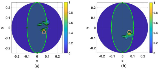
Figure 4.
Obtained microwave images of anechoic chamber phantom experiments using frequency 1 GHz to 5 GHz, (a) applying “rotation subtraction” method, (b) employing the “ideal” method. The light green ellipse indicates the phantom region, while the area marked with a red circle shows the exact position of inclusion and the dimension of the circle is in relation to the dimension of the inclusion. Axes scales are meters.
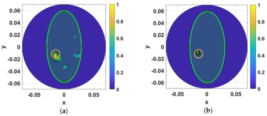
Figure 5.
Obtained microwave images of MammoWave device phantom experiments using frequency 1 GHz to 6.5 GHz, (a) applying “rotation subtraction” method, (b) employing the “ideal” method. The light green ellipse indicates the phantom region, while the area marked with a red circle shows the exact position of inclusion and the dimension of the circle is in relation to the dimension of the inclusion. Axes scales are meters.
In addition, to evaluate the performance of different artifact removal methods in the lung lesion detection, whether performed inside the anechoic chamber or using the MammoWave device, a metric called SCR has been introduced to quantify and compare the results. The obtained SCR values have been summarized in Table 2.
Table 2.
SCR for microwave images of phantom measurements in both the anechoic chamber and MammoWave device.
Figure 4a,b show the microwave images obtained from anechoic chamber phantom experiments. Figure 4a refers to the obtained microwave image after applying the “rotation subtraction” method by subtracting the obtained S21 of the transmitting position and transmitting position . In spite of some clutters existing in Figure 4a, however, detection clearly has been achieved with an SCR = 4.65 dB. Figure 4b illustrates the microwave image after performing the “ideal” method. As can be observed in Figure 4b, the inclusion has been visually detected in the right position with less clutter, having an SCR = 7 dB.
Turning now to the MammoWave device, the obtained microwave images of the miniaturized lung lesion phantom experiments have been shown in Figure 5a,b.
Figure 5a indicates the obtained image of the lung phantom corresponding to employing the rotation subtraction artifact removal procedure. As is apparent, in Figure 5a the detection of inclusion has been successfully achieved in its correct position, with an SCR = 6 dB. Figure 5b represents the result of applying the “ideal” artifact removal procedure. As Figure 5b illustrates, the inclusion is visible with less residual clutter and the detection has been achieved properly, with an SCR = 9.88 dB.
For both the anechoic chamber and the MammoWave, the highest SCR values (7 dB and 9.88 dB, respectively) are achieved when applying the “ideal” artifact removal method; the higher SCR in the MammoWave, is probably due also to the fact that the device employs more transmitting positions.
Ultimately, to further investigate the lung lesion detection capability through the proposed method, a more realistic and complex scenario was considered. The measurement was repeated using the re-miniaturized torso phantom having two cylindrical inclusions with different radii (0.7 cm and 0.25 cm) filled with tap water to mimic the lung lesion. The re-miniaturized torso phantom, with external layer dimension of , and internal layer dimension of has been constructed by considering the same tissue-mimicking materials as the previous phantom. Figure 6a,b present the fabricated re-miniaturized torso phantom, the position of the torso phantom inside the Mammowave device, respectively. Moreover, Figure 6c shows the S21 for both the phantom with and without inclusions, calculated when the transmitting antenna is and the receiving antenna is apart.
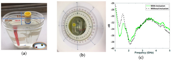
Figure 6.
(a–c) Depict the fabricated re-miniaturized torso phantom, the position of the torso phantom inside the Mammowave device, the S21 for both the phantom with and without inclusions, calculated when the transmitting antenna is and the receiving antenna is apart, respectively.
Finally, Figure 7a,b shows the obtained images of the Mammowave device using the re-miniaturized torso phantom employing the “rotation subtraction” and “ideal” artifact removal methods, respectively, confirming that the detection can also be achieved in more complex scenarios such as a phantom with two inclusions of varying sizes. As Figure 7a indicates, some clutter exists in the obtained images, however, both inclusions can be clearly observed in their approximate positions, having SCR = 5.2 dB. Turning now to Figure 7b, the detection of both inclusions was completed with more clarity and less clutter, achieving SCR = 6.19 dB.
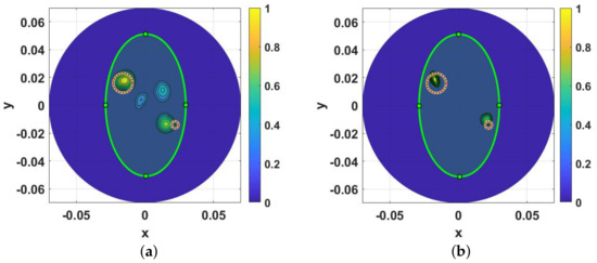
Figure 7.
Reconstructed images of the lung phantom with two inclusions. (a,b) represent the images corresponding to applying the “rotation subtraction” artifact removal method and “ideal” artifact removal method, respectively. The light green ellipse indicates the phantom region, while the areas marked with red circles show the exact positions of the inclusions and the dimension of each circle is in relation to the dimension of the inclusion. Axes’ scales are meters.
A limitation of this study is represented by the fact that the phantoms we constructed do not fully represent the heterogeneity of the human torso. For example, they did not represent the alternate distribution of ribs and muscle, which are mimicked using a dedicated layer having average dielectric properties. The heterogeneity of the human torso might reduce the SCR; this eventual reduction will be assessed via dedicated clinical trials, which are planned as the next step.
4. Conclusions
In this paper we presented the experimental validation of an HP-based MWI procedure to detect lung lesions in phantoms, both inside an anechoic chamber and using the MammoWave. Specifically, the detection was first achieved through dedicated multilayer oval-shaped torso phantom measurements using anechoic chamber equipment including two antennas employed from 1 to 5 GHz. Then, a miniaturized torso phantom investigation using an MWI device was performed by using different scenarios such as torso phantoms having two different sizes of cylindrical inclusions. Considering the possibility of existing artifacts (i.e., the transmitter’s image or the first layer phantom’s reflection) in the generated images, and in order to avoid masking the region of inclusion, two different artifact removal methods were applied to suppress them before reconstructing the images. Consequently, lung lesion identification was achieved through two following artifact removal methods: first, applying the “rotation subtraction” method by subtracting data between two adjacent transmitting positions, and then performing the “ideal” artifact removal method, via subtraction between received data of the healthy torso and non-healthy torso. Thus, the capability of both artifact removal procedures in achieving the detection has been proven. The SCR was calculated to quantify the obtained images, achieving 9.88 dB by employing the “ideal” artifact removal method using the MammoWave device.
Future steps will involve the construction of a dedicated MWI device, i.e., a modified version of the MammoWave, which could be used to perform clinical trials for lung imaging. Such device can be used for the purpose of monitoring the lung lesion without any concern for the presence of X-Rays, while its portability and low complexity of its structure will be other benefits of this device. Thus, it might also provide the opportunity for performing remote pre-hospital examinations. Due to the nominal output power of the VNA (1 mW) used for these experiments, the specific absorption rate (SAR) does not represent an issue; however, in case the output power should be increased, SAR would be appropriately monitored.
Author Contributions
Conceptualization, B.K. (Banafsheh Khalesi), M.G. and G.T.; methodology, B.K. (Banafsheh Khalesi), B.K. (Bilal Khalid), N.G., G.R. and G.T.; supervision, M.G. and S.D.-M.; validation, B.K. (Banafsheh Khalesi), B.K. (Bilal Khalid), N.G., G.R., M.G., S.D.-M. and G.T.; writing—original draft preparation, B.K. (Banafsheh Khalesi) and N.G.; writing—review and editing, M.G., S.D.-M. and G.T. All authors have read and agreed to the published version of the manuscript.
Funding
This project has received funding from the European Union’s Horizon 2020 research and innovation program under grant agreements No: 872752, 101017098.
Conflicts of Interest
Navid Ghavami, Giovanni Raspa and Gianluigi Tiberi are employed by UBT—Umbria Bioengineering Technologies/by its subsidiary UBT UK Division.
References
- Kalender, W.A. Computed tomography: Fundamentals. In System Technology, Image Quality, Applications; John Wiley & Sons: Hoboken, NJ, USA, 2011. [Google Scholar]
- Kim, K.; Choi, H. High-efficiency high-voltage class F amplifier for high-frequency wireless ultrasound systems. PLoS ONE 2021, 16, e0249034. [Google Scholar] [CrossRef] [PubMed]
- Pastorino, M.; Randazzo, A. Microwave Imaging Methods and Applications; Artech House: Boston, MA, USA, 2018. [Google Scholar]
- Byrne, D. An Introduction to Microwave Imaging for Breast Cancer Detection; Biological and Medical Physics, Biomedical Engineering; Springer International Publishing: Basel, Switzerland, 2016; pp. 47–73. [Google Scholar]
- Khalesi, B.; Sohani, B.; Ghavami, N.; Ghavami, M.; Dudley, S.; Tiberi, G. A phantom investigation to quantify Huygens principle based microwave imaging for bone lesion detection. Electronics 2019, 8, 1505. [Google Scholar] [CrossRef] [Green Version]
- Khalesi, B.; Sohani, B.; Ghavami, N.; Ghavami, M.; Dudley, S.; Tiber, G. Free-Space Operating Microwave Imaging Device for Bone Lesion Detection: A Phantom Investigation. IEEE Antennas Wirel. Propag. Lett. 2020, 19, 2393–2397. [Google Scholar] [CrossRef]
- Babarinde, O.J.; Jamlos, M.F.; Ramli, N.B. UWB microwave imaging of the lungs: A review. In Proceedings of the 2014 IEEE 2nd International Symposium on Telecommunication Technologies (ISTT), Langkawi, Malaysia, 24–26 November 2014; pp. 188–193. [Google Scholar]
- Zamani, A.; Rezaeieh, S.A.; Abbosh, A.M. Lung cancer detection using frequency-domain microwave imaging. Electron. Lett. 2015, 51, 740–741. [Google Scholar] [CrossRef]
- Rezaeieh, S.A.; Zamani, A.; Bialkowski, K.S.; Abbosh, A.M. Novel microwave torso scanner for thoracic fluid accumulation diagnosis and monitoring. Sci. Rep. 2017, 7, 304. [Google Scholar] [CrossRef] [PubMed]
- Muhammad, S.N.; Isa, M.M.; Jamlos, F. Review article of microwave imaging techniques and dielectric properties for lung tumor detection. AIP Conf. Proc. 2020, 2203, 20012. [Google Scholar]
- Lin, X.; Gong, Z.; Ding, Y.; Chen, Y.; Sosa, P.A.V.; Sosa, M.J.V. Feasibility Study of Detection of Coronavirus Disease 2019 with Microwave Medical Imaging. In Proceedings of the 2021 15th European Conference on Antennas and Propagation (EuCAP), Dusseldorf, Germany, 22–26 March 2021; pp. 1–4. [Google Scholar]
- Alam, N.; Ahmed, A.; Oni, M.A.I.; Meen, T.A.; Rahman, M.A. UWB Microwave Imaging for Non-Invasive Anomaly Detection in Human Lung and Possible Application in COVID-19 Diagnosis: A Review. In Proceedings of the 2021 2nd International Conference on Robotics, Electrical and Signal Processing Techniques (ICREST), Dhaka, Bangladesh, 5–7 January 2021; pp. 772–776. [Google Scholar] [CrossRef]
- Khalesi, B.; Khalid, B.; Ghavami, N.; Ghavami, M.; Dudley, S.; Tiberi, G. Microwave Imaging for Lung COVID-19 Infection Detection through Huygens Principle. In Proceedings of the 2021 Photonics & Electromagnetics Research Symposium (PIERS 2021), Hangzhou, China, 21–25 November 2021. [Google Scholar]
- Ghavami, N.; Tiberi, G.; Edward, D.J.; Monorchio, A. UWB Microwave Imaging of Objects with Canonical Shape. IEEE Trans. Antennas Propag. 2012, 60, 231–239. [Google Scholar] [CrossRef]
- Ender, P. Huygens’ principle as universal model of propagation. Latin Amer. J. Phys. Educ. 2009, 3, 19–32. [Google Scholar]
- Vispa, A.; Sani, L.; Paoli, M.; Bigotti, A.; Raspa, G.; Ghavami, N.; Caschera, S.; Ghavami, M.; Duranti, M.; Tiberi, G. UWB Device for Breast Microwave Imaging: Phantom and Clinical Validations. Measurement 2019, 146, 582–589. [Google Scholar] [CrossRef]
- Camacho, L.M.; Tjuatja, S. FDTD simulation of microwave scattering from a lung tumor. In Proceedings of the IEEE Antennas and Propagation Society International Symposium, Washington, DC, USA, 3–8 July 2005; pp. 815–818. [Google Scholar]
- Hasgall, P.A.; Neufeld, E.; Gosselin, M.C.; Klingenböck, A.; Kuster, N.; Kuster, N.; Hasgall, P.; Gosselin, M. IT’IS Database for Thermal and Electromagnetic Parameters of Biological Tissues, Version 4.0; ScienceOpen: Berlin, Germany, 2018. [Google Scholar]
- Gabriel, C.; Gabriel, S.; Corthout, E. The dielectric properties of biological tissues: I. literature survey. Phys. Med. Biol. 1996, 41, 2231–2249. [Google Scholar] [CrossRef] [PubMed] [Green Version]
- Zurich Med Tech. Available online: https://zmt.swiss/validation-hw/tsm/tle5c-24-2450/ (accessed on 26 October 2019).
- Meaney, P.M.; Fox, C.J.; Geimer, S.D.; Paulsen, K.D. Characterization of Glycerin: Water Mixtures: Implications for Use as a Coupling Medium in Microwave Tomography. IEEE Trans. Microw. Theory Tech. 2017, 65, 1471–1478. [Google Scholar] [CrossRef] [PubMed] [Green Version]
- Tiberi, G.; Ghavami, N.; Edwards, D.J.; Monorchio, A. Ultrawideband microwave imaging of cylindrical objects with inclusions. IET Microw. Antennas Propag. 2011, 5, 1440–1446. [Google Scholar] [CrossRef]
- Fear, E.C.; Li, X.; Hagness, S.C.; Stuchly, M.A. Confocal microwave imaging for breast cancer detection: Localization of tumors in three dimensions. IEEE Trans. Biomed. Eng. 2002, 49, 812–822. [Google Scholar] [CrossRef] [PubMed] [Green Version]


Publisher’s Note: MDPI stays neutral with regard to jurisdictional claims in published maps and institutional affiliations. |
© 2022 by the authors. Licensee MDPI, Basel, Switzerland. This article is an open access article distributed under the terms and conditions of the Creative Commons Attribution (CC BY) license (https://creativecommons.org/licenses/by/4.0/).