
Application of Model-Based Software Testing in the Health Care Domain


Abstract
:1. Introduction
1.1. Basic Definitions and Concepts
1.1.1. UML Activity Diagram Modeling
- Activity nodes: There are three different types of nodes in the activity diagrams.
- Action nodes (AN): take all input data and control tokens, make new tokens, and transmits them to output activity edges once they are ready.
- Control nodes (CN): tokens are routed through the graph by control nodes. The control nodes have components for deciding between different flows (decision/merge), splitting or merging the flow for parallel processing (fork/join), and so on.
- Object nodes (ON): these nodes give and take the data tokens. They can also operate as buffers, collecting tokens while waiting to go downstream
- Activity edges: In activity diagrams, there are two different types of edges.
- Control flow edge: this edge depicts the flow of control throughout the activity
- Object flow edge: this edge depicts the movement of items during the activity. In this article, we concentrate on the data and control flow of activity diagrams, both of which are critical for test generation.
- 1.
- is a set of activity states with a finite number of possibilities;
- 2.
- is a set of completion transitions with a finite number of possibilities;
- 3.
- denotes a set of guard conditions, and corresponds to the transition ;
- 4.
- denotes the flow relationship between the transitionsand activity states ;
- 5.
- denotes the starting activity state; the end activity state is denoted by
1.1.2. Testing Scenario: A Diabetes Telehealth Care
- Determine whether the patient has diabetes.
- Determine whether the patient’s blood glucose level is larger than or less than 120.
- Determine whether the glucose level is greater than or less than 120.
- Determine the kind of diabetes the cloud-based healthcare system can process large amounts of data and convert it into useful information
1.2. Research Gap and Contributions
- We have proposed an algorithm based on the depth first search technique to generate test cases to detect diabetes.
- We present how to draw an activity flow graph (AFG) from an activity diagram.
- We show how acceptance testing can be used to ensure that the software correctly predicts diabetes type from the blood sugar level.
2. Related Works
3. Proposed Work
- The healthcare cloud system is a deterministic system with accurate and predictable behavior, and
- We overlook the part of telehealth care dealing with the doctor application because it is the same as the patient application
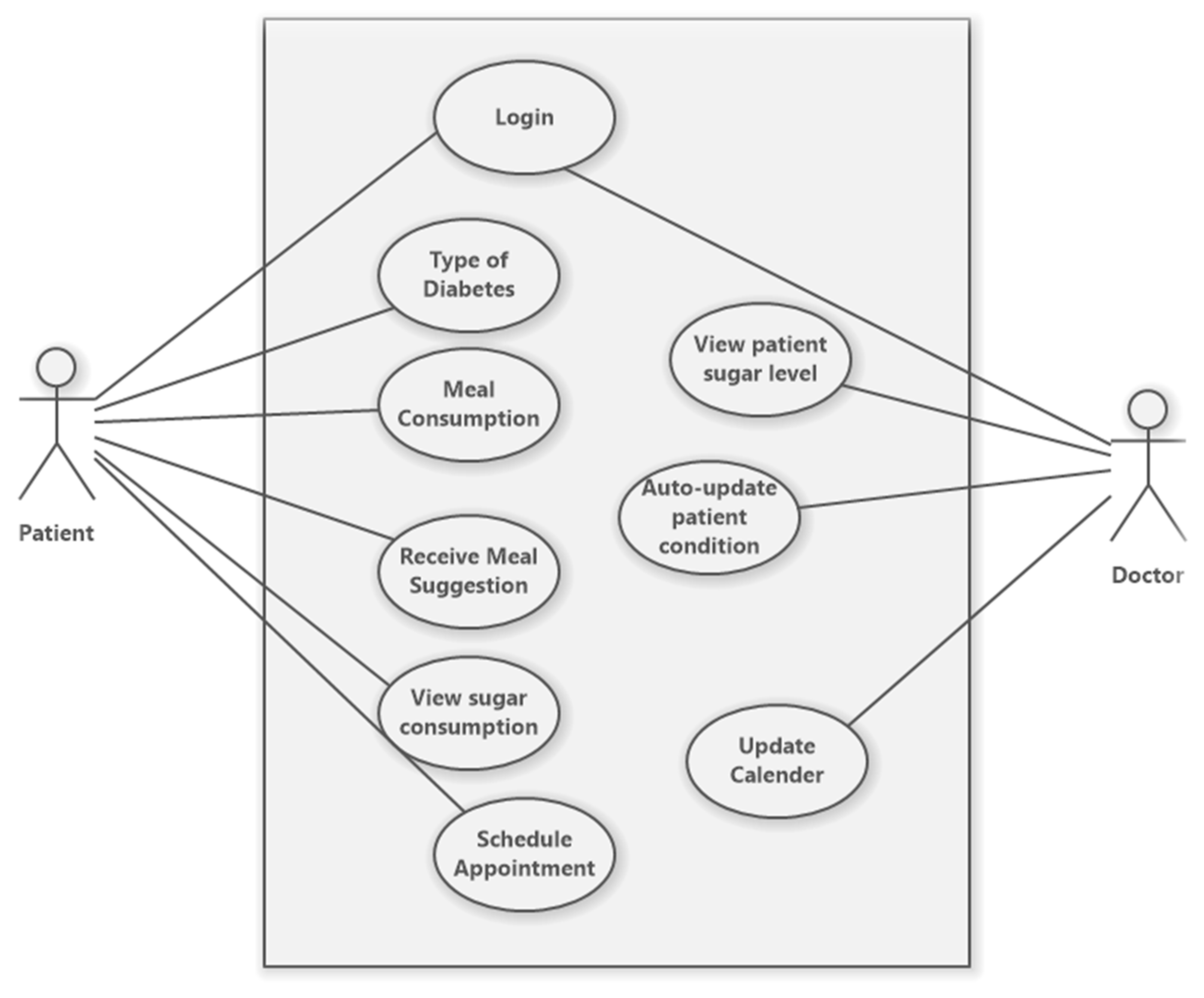
3.1. Use Case Test Scenario
3.2. Case Study for an Activity Definition of a Scenario and a Test Case
- The patient enters his or her login credentials.
- The existing database of registered users is used to validate these credentials.
- The user gets forwarded to the dashboard page if the login is successful.
- The server sends the SMS to the doctor for verification when the patient selects the appointment schedule.
- The patient then waits for the doctor to send a confirmation text message.
- Once the confirmation is received, the doctor will review all of the patient’s issues as well as the type of diabetes they have. They will then recommend how much food to eat, how to monitor sugar consumption, how to receive meal suggestions, and how to update their app for future use.
3.3. Generation of Test Cases from the Activity Diagram
- Create an activity diagram for the specific use case, complete with the relevant test data.
- Create an activity flow graph from the activity diagram.
- Extract the relevant information by traversing the activity flow graph.
- Create test cases using the activity diagram as a guide.
- Construction of the activity diagram with the required test information: In order to develop test scenarios, we employ UML models to define a system’s need. One or more activity diagrams can be used to depict each use case. A telehealth care scenario is depicted in Figure 1.
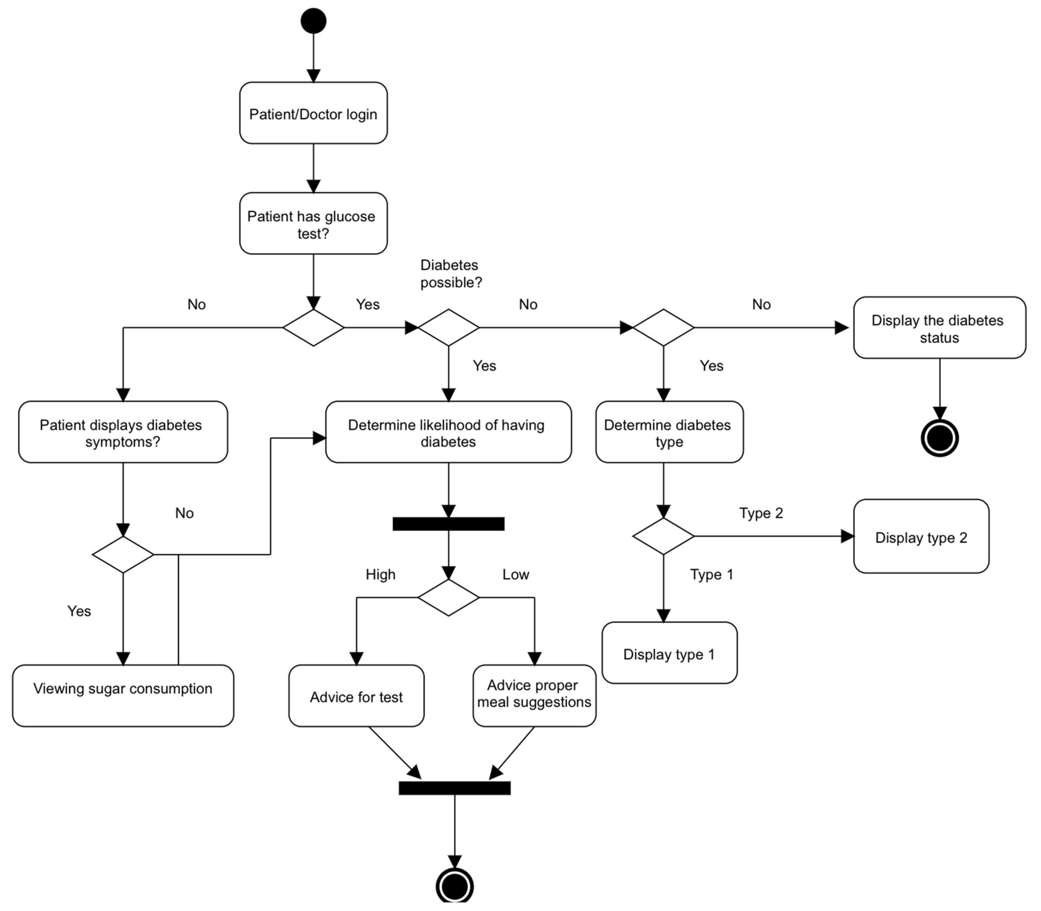
- The scenario related to a use case (Figure 2) is represented in activity diagrams: A scenario is a completed “path” across the activity diagram where users of the system have several alternatives for carrying out the functionality indicated in the use case. The main scenario begins at the start node and goes without mistake through all intermediate nodes until it reaches the end node. The guidelines for modeling relevant test data into an activity diagram are outlined in the next paragraph.
- Converting activity diagram into activity flow graph: An activity diagram to activity graph conversion approach is provided. The following steps are used to convert the activity diagram into an activity flow graph:
- The activity flow graph is constructed from start to finish node displaying options, conditions, concurrent executions, and loop expressions.
- Create a control flow activity entry for each conditional expression. Create nodes in the activity flow graph by traversing the control flow graph.
- Conditional statements are created from loop statements.
- In each concurrent execution statement, an entry is made in the control flow graph for each execution path and then represented in the activity flow graph by different execution paths.
- Extraction of all required information by traversing the activity flow graph: All necessary data, such as nodes, edges, conditional statements, and so on, are extracted. An activity transition graph can be thought of as a node for each action in an activity flow graph. Multiple control flow sequences are found using the depth-first traversal strategy to traverse the activity flow graph. We seek conditional predicates at each transition during traversal. In this phase, double-check the process to confirm that all required fields have been filled in, such as activity information, input, output, and conditions. Enumerate all feasible paths from the start node to the final node in the activity flow graph and each path visited to generate test cases, to generate test cases that satisfy the activity path criteria. To produce all activity paths, we suggest a pseudo-code of test cases.
- Generating the test cases from the activity flow graph: Using the DFS approach, different flow sequences are detected by traversing the activity flow graph (AFG). The activity path coverage requirement is used to generate the test scripts. To do this, we gather all activity paths from the start node to the end node. To generate test cases that match the activity path criteria, we first enumerate all conceivable paths from the start node to the final node in the activity diagram, Figure 2.
| Algorithm 1. GenTestCase |
| Input: Activity flow diagram Output: Activity paths 1: Enumerate and store all paths from the start node to the end node in 2: X = f 3: for each (P[i]), 1 ≤ i ≤ n do 4: N(Node) = StartNode 5: 6: Pre-Condition of the activity 7: Post-Condition of the activity 8: 9: while do 10: if Condition = NULL then 11: 12: else if Condition NULL 13: 14: 15: end if 16: 17: end while 18: (the pre-condition, input values, resultant values and the post condition of the End Node) 19: 20: 21: end for 22: Return |
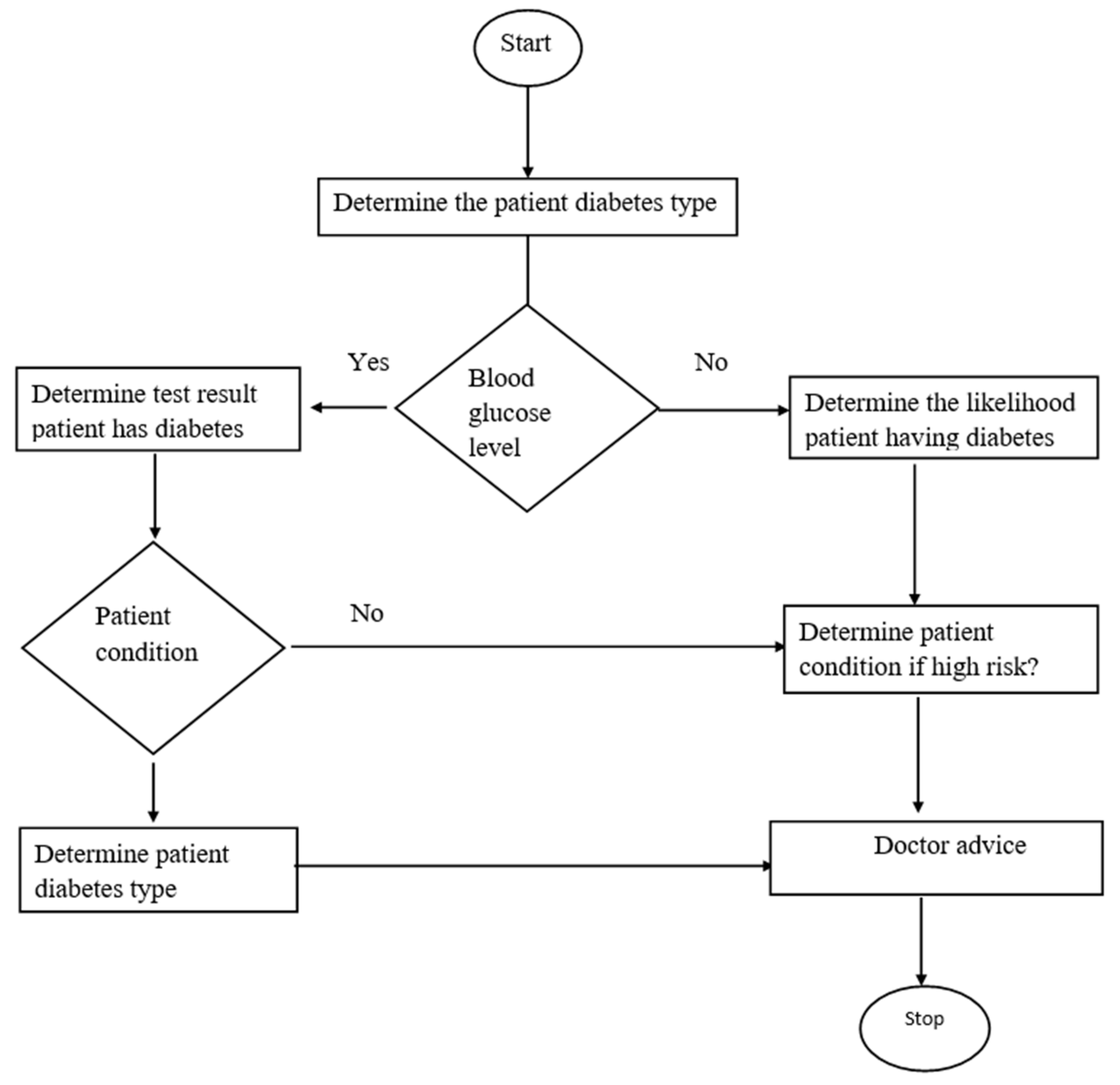
3.4. Case Study
- Step 1: Start
- Step 2: Determine if the patient has diabetes
- Step 3: Does the patient have a blood glucose test?
- Step 4: If No—Ask the patient to get tested and go to Step 6
- Step 5: If yes—Go to Step 6
- Step 6: Check the glucose level
- Step 7: If glucose level > 120—declare patient has diabetes and go to Step 9
- Step 8: If glucose level ≤ 120—declare patient does not have diabetes
- Step 9: Determine the patient diabetes types.
- Step 10: Is RPG (RPG is random plasma glucose) ≥ 11.1?
- Step 11: Is respondent insulin-resistant?
- Step 12: If yes, Diabetes symptoms progress slowly?
- Step 13: Print “Type 2 diabetes”
- Step 14: If no, diabetes symptoms progress fast?
- Step 15: Print “Type 1 diabetes”
- Step 16: Advice proper treatment to respondent
- Step 17: End
3.5. Activity Diagram and CFAMT Table
3.6. Test Sequence Generation
- Pre-condition:
- The patient should have a valid blood report.
- Post-condition:
- Determines if the patient has diabetes.
- Determines the type of diabetes.
- Advise proper treatment.
- Main scenario
- The patient uploads a valid blood test report.
- The patient enters the glucose level and RPG value
- The user receives information about the type of diabetes and proper treatment.
3.7. Test Case Generation
4. Discussion and Conclusions
Author Contributions
Funding
Conflicts of Interest
References
- Leotta, M.; Ricca, F.; Clerissi, D.; Ancona, D.; Delzanno, G.; Ribaudo, M.; Franceschini, L. Towards an acceptance testing approach for Internet of Things systems. In Proceedings of the International Conference on Web Engineering, Rome, Italy, 5–8 June 2017; Springer: Cham, Switzerland, 2017; pp. 125–138. [Google Scholar]
- Rosenkranz, P.; Wählisch, M.; Baccelli, E.; Ortmann, L. A distributed test system architecture for open-source IoT soft-ware. In Proceedings of the 1st Workshop on IoT Challenges in Mobile and Industrial Systems (IoT-Sys 2015), Florence, Italy, 18 May 2015; ACM: New York, NY, USA, 2015; pp. 43–48. [Google Scholar]
- Sharma, S.; Chen, K.; Sheth, A. Toward practical privacy-preserving analytics for IoT and cloud-based healthcare systems. IEEE Internet Comput. 2018, 22, 42–51. [Google Scholar] [CrossRef] [Green Version]
- Huang, H.; Gong, T.; Ye, N.; Wang, R.; Dou, Y. Private and secured medical data transmission and analysis for wireless sensing healthcare system. IEEE Trans. Ind. Inform. 2017, 13, 1227–1237. [Google Scholar] [CrossRef]
- Lin, C.C.; Lin, P.Y.; Lu, P.K.; Hsieh, G.Y.; Lee, W.L.; Lee, R.G. A healthcare integration system for disease assessment and safety monitoring of dementia patients. IEEE Trans. Inf. Technol. Biomed. 2008, 12, 579–586. [Google Scholar] [PubMed]
- Das, P.S.; Park, J.Y. A flexible touch sensor based on conductive elastomer for biopotential monitoring applications. Biomed. Signal Process. Control 2017, 33, 72–82. [Google Scholar] [CrossRef]
- Nagarajan, S.M.; Deverajan, G.G.; Chatterjee, P.; Alnumay, W.; Ghosh, U. Effective task scheduling algorithm with deep learning for Internet of Health Things (IoHT) in sustainable smart cities. Sustain. Cities Soc. 2021, 71, 102945. [Google Scholar] [CrossRef]
- Nagarajan, S.M.; Deverajan, G.G.; Kumaran, U.; Thirunavukkarasan, M.; Alshehri, M.D.; Alkhalaf, S. Secure data transmission in internet of medical things using res-256 algorithm. IEEE Trans. Ind. Inform. 2021. [Google Scholar] [CrossRef]
- Vieira, M.; Song, X.; Matos, G.; Storck, S.; Tanikella, R.; Hasling, B. Applying model-based testing to healthcare products: Preliminary experiences. In Proceedings of the 30th International Conference on Software Engineering, Leipzig, Germany, 10–18 May 2008; pp. 669–672. [Google Scholar]
- Borycki, E.M.; Monkman, H.; Griffith, J.; Kushniruk, A.W. Mobile usability testing in healthcare: Methodological approaches. In MEDINFO 2015: eHealth-Enabled Health; IOS Press: Amsterdam, The Netherlands, 2015; pp. 338–342. [Google Scholar]
- Holmes, S.; Moorhead, A.; Bond, R.; Zheng, H.; Coates, V.; McTear, M. Usability testing of a healthcare chatbot: Can we use conventional methods to assess conversational user interfaces? In Proceedings of the 31st European Conference on Cognitive Ergonomics, Belfast, UK, 10–13 September 2019; pp. 207–214. [Google Scholar]
- Dey, J. A “new normal” Approach in Post-COVID19 Era: Online Healthcare Testing Strategy. J. Math. Sci. Comput. Math. 2020, 2, 145–157. [Google Scholar] [CrossRef]
- Jabbar, R.; Krichen, M.; Fetais, N.; Barkaoui, K. Adopting formal verification and model-based testing tech-niques for validating a blockchain-based healthcare records sharing system. In Proceedings of the 22nd International Conference on Enterprise In-formation Systems, Prague, Czech Republic, 5–7 May 2020; SCITEPRESS-Science and Technology Publications: Setúbal, Portugal, 2020; pp. 261–268. [Google Scholar]
- Klonoff, D.C. The current status of mHealth for diabetes: Will it be the next big thing? J. Diabet. Sci. Technol. 2013, 7, 749–758. [Google Scholar] [CrossRef] [PubMed] [Green Version]
- Islam, S.R.; Kwak, D.; Kabir, M.H.; Hossain, M.; Kwak, K.S. The internet of things for health care: A comprehensive survey. IEEE Access 2015, 3, 678–708. [Google Scholar] [CrossRef]
- Kim, H.; Ahmad, A.; Hwang, J.; Baqa, H.; Le Gall, F.; Ortega, M.A.R.; Song, J. IoT-TaaS: Towards a prospective IoT testing framework. IEEE Access 2018, 6, 15480–15493. [Google Scholar] [CrossRef]
- Silva, L.C.; Perkusich, M.; Bublitz, F.M.; Almeida, H.O.; Perkusich, A. A model-based architecture for test-ing medical cyber-physical systems. In Proceedings of the 29th Annual ACM Symposium on Applied Computing, Gyeongju, Korea, 24–28 March 2014; pp. 25–30. [Google Scholar]
- Leotta, M.; Clerissi, D.; Olianas, D.; Ricca, F.; Ancona, D.; Delzanno, G.; Franceschini, L.; Ribaudo, M. An acceptance testing approach for Internet of Things systems. IET Softw. 2018, 12, 430–436. [Google Scholar] [CrossRef]
- Chen, T.Y.; Ho, J.W.; Liu, H.; Xie, X. An innovative approach for testing bioinformatics programs using metamorphic testing. BMC Bioinf. 2009, 10, 24. [Google Scholar] [CrossRef] [PubMed] [Green Version]
- STAM F2761-2009; Medical Devices and Medical Systems—Essential Safety Requirements for Equip-ment Comprising the Patient-Centric Integrated Clinical Environment (ICE), Part 1: General Requirements and Conceptual Model. ASTM International: West Conshohocken, PA, USA, 2009.
- Lee, I.; Sokolsky, O.; Chen, S.; Hatcliff, J.; Jee, E.; Kim, B.; King, A.; Mullen-Fortino, M.; Park, S.; Roederer, A.; et al. Challenges and research directions in medical cyber-physical systems. Proc. IEEE 2012, 100, 75–90. [Google Scholar]
- Lee, I.; Sokolsky, O. Medical cyber physical systems. In Proceedings of the 2010 47th Design Automation Conference (DAC), Anaheim, CA, USA, 13–18 June 2010; ACM/IEEE: New York, NY, USA, 2010; pp. 743–748. [Google Scholar]
- Pajic, M.; Mangharam, R.; Sokolsky, O.; Arney, D.; Goldman, J.; Lee, I. Model-driven safety analysis of closed-loop medical systems. IEEE Trans. Ind. Inform. 2012, 10, 3–16. [Google Scholar] [CrossRef] [PubMed] [Green Version]
- Jiang, Z.; Pajic, M.; Mangharam, R. Model-based closed-loop testing of implantable pacemakers. In Proceedings of the 2011 IEEE/ACM Second International Conference on Cyber-Physical Systems, Chicago, IL, USA, 12–14 April 2011; IEEE: New York, NY, USA; pp. 131–140. [Google Scholar]
- Arrieta, A.; Sagardui, G.; Etxeberria, L.; Zander, J. Automatic generation of test system instances for configurable cyber-physical systems. Softw. Qual. J. 2017, 25, 1041–1083. [Google Scholar] [CrossRef]
- Hatcliff, J.; King, A.; Lee, I.; Macdonald, A.; Fernando, A.; Robkin, M.; Vasserman, E.; Weininger, S.; Goldman, J.M. Rationale and architecture principles for medical application platforms. In Proceedings of the 2012 IEEE/ACM Third International Conference on Cyber-Physical Systems (ICCPS’12), Beijing, China, 17–19 April 2012; IEEE Computer Society: Washington, DC, USA, 2012; pp. 3–12. [Google Scholar]
- Miller, B.; Vahid, F.; Givargis, T. Digital mockups for the testing of a medical ventilator. In Proceedings of the 2nd ACM SIGHIT International Health Informatics Symposium (IHI’12), Miami, FL, USA, 28–30 January 2012; ACM: New York, NY, USA, 2012; pp. 859–862. [Google Scholar]
- Lee, E.A. Cyber physical systems: Design challenges. In Proceedings of the 2008 11th IEEE Symposium on Object Oriented Real-Time Distributed Computing (ISORC’08), Orlando, FL, USA, 5–7 May 2008; IEEE Computer Society: Washington, DC, USA, 2008; pp. 363–369. [Google Scholar]
- Lee, E.A.; Seshia, S.A. Introduction to Embedded Systems, A Cyber-Physical Systems Approach; MIT Press: Cambridg, MA, USA, 2011; ISBN 978-0-557-70857-4. [Google Scholar]
- Dimitri, G.M.; Spasov, S.; Duggento, A.; Passamonti, L.; Toschi, N. Unsupervised stratification in neuroimaging through deep latent embeddings. In Proceedings of the 2020 42nd Annual International Conference of the IEEE Engineering in Medicine & Biology Society (EMBC), Montreal, QC, Canada, 20–24 July 2020; IEEE: New York, NY, USA, 2020; pp. 1568–1571. [Google Scholar]
- Esteva, A.; Robicquet, A.; Ramsundar, B.; Kuleshov, V.; DePristo, M.; Chou, K.; Cui, C.; Corrado, G.; Thrun, S.; Dean, J. A guide to deep learning in healthcare. Nat. Med. 2019, 25, 24–29. [Google Scholar] [CrossRef] [PubMed]
- Miotto, R.; Wang, F.; Wang, S.; Jiang, X.; Dudley, J.T. Deep learning for healthcare: Review, opportunities and challenges. Brief. Bioinform. 2018, 19, 1236–1246. [Google Scholar] [CrossRef] [PubMed]
- Vaid, A.; Somani, S.; Russak, A.J.; De Freitas, J.K.; Chaudhry, F.F.; Paranjpe, I.; Johnson, K.W.; Lee, S.J.; Miotto, R.; Richter, F.; et al. Machine learning to predict mortality and critical events in a cohort of patients with COVID-19 in New York City: Model development and validation. J. Med. Internet Res. 2020, 22, e24018. [Google Scholar] [CrossRef] [PubMed]
- Abomhara, M.; Lazrag, M.B. UML/OCL-based modeling of work-based access control policies for collaborative healthcare systems. In Proceedings of the 2016 IEEE 18th International Conference on e-Health Networking, Applications and Services (Healthcom), Munich, Germany, 14–16 September 2016; IEEE: New York, NY, USA, 2016; pp. 1–6. [Google Scholar]
- Pişirgen, A.; Peker, S. A UML-Based Conceptual Model for Appointment Booking Systems. In Proceedings of the 2021 6th International Conference on Computer Science and Engineering (UBMK), Ankara, Turkey, 15–17 September 2021; IEEE: New York, NY, USA, 2021; pp. 812–817. [Google Scholar]
- Veitaite, I.; Lopata, A. Knowledge-based UML dynamic models generation from enterprise model in hospital information management process example. Intell. Syst. Sustain. Pers. -Cent. Healthc. 2022, 205, 225–250. [Google Scholar] [CrossRef]
- Utting, M.; Legeard, B. Practical Model-Based Testing: A Tools Approach; Elsevier: Amsterdam, The Netherlands, 2010. [Google Scholar]
- Wang, L.; Yuan, J.; Yu, X.; Hu, J.; Li, X.; Zheng, G. Generating test cases from UML activity diagrambased on gray-box method. In Proceedings of the 11th Asia-Pacific Software Engineering Conference, Busan, Korea, 30 November–3 December 2004; IEEE: New York, NY, USA, 2004; pp. 284–291. [Google Scholar]

| Activity Diagram | An activity diagram , is a 6-tuple where:
Also, there can be only one transition t such that the following is satisfied |
| Test Sequence | A test sequence, , in an activity diagram, , can be defined as an execution path from the starting activity state to the end activity state consisting of activi-ties and transitions, i.e., , where , , is the initial state and is the final state. is the set of test sequences. |
| Basic Paths (BP) | We ensure that all action states and transitions are covered and that the loops are only run once while utilizing the DFS (Depth First Search method) to traverse an activity diagram from the initial activity state to the final activity state. As a result, we can obtain all basic paths. |
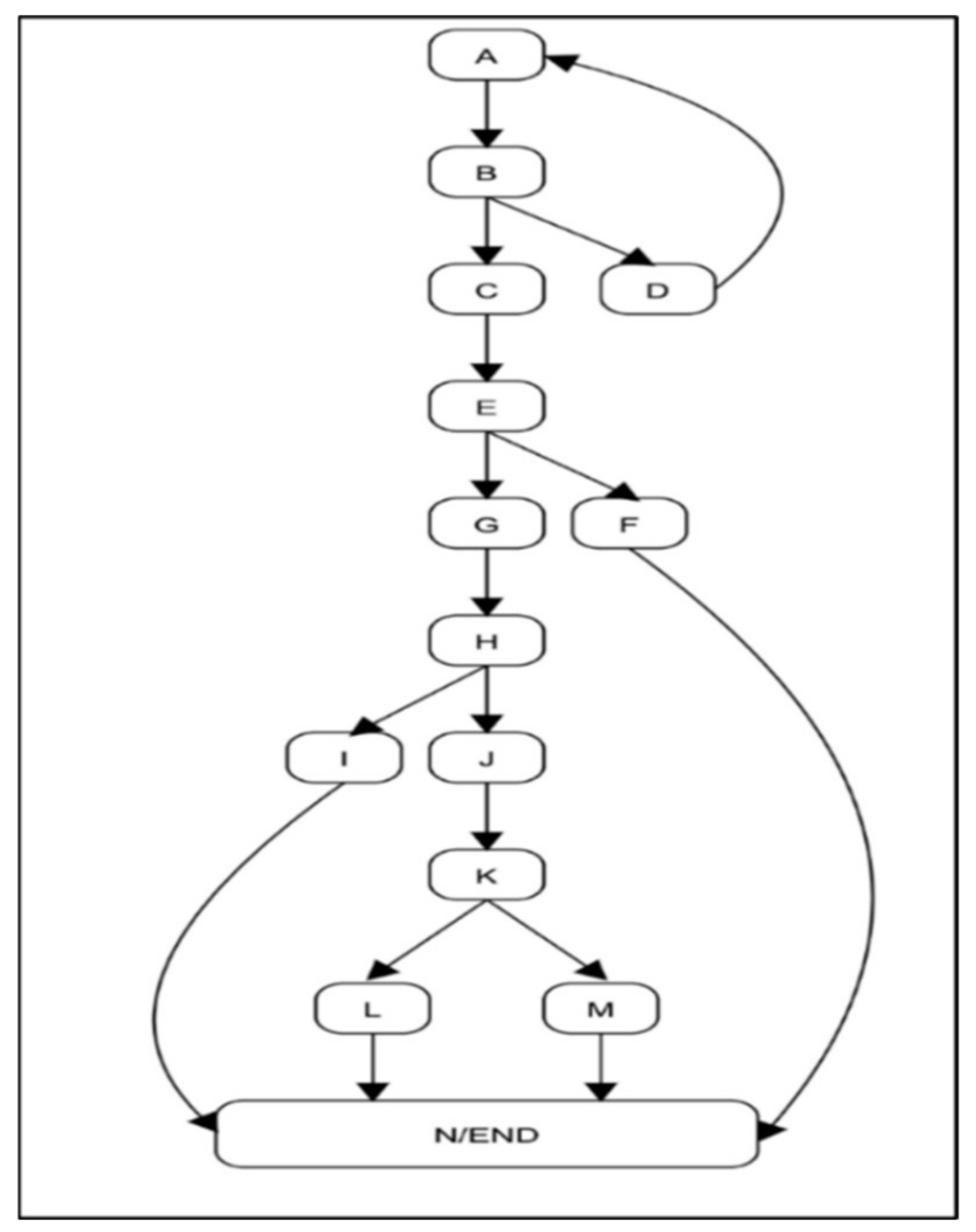
| Activity Flow Diagram (AFG) | An activity flow graph is a directed network in which each node represents a construct, such as a starting node, a flow final node, a decision mode, a guard condition, a fork node, a join node, a merging node, and so on, and each edge represents the flow in the activity diagram |
| Control Flow Activity Mapping Diagram (CFAMT) | CFAMT is a table that stores information about each activity corresponds to a node in an activity graph |
| Name of the Node | Name of the Activities | Predicate Conditions |
|---|---|---|
| A | Upload the blood report | NULL |
| B | Check the blood report | NULL |
| C | Valid report | B1: Valid report |
| D | Invalid report | B2: Invalid report |
| E | Check glucose Level | NULL |
| F | Glucose level ≤ 120 | E1: No diabetes |
| G | Glucose level >120 | E2: Patient has diabetes |
| H | Check RPG level | NULL |
| I | RPG < 11.1 | H1: Advice precautionary treatment |
| J | RPG ≥ 11.1 | H2: Check diabetes type |
| K | Check insulin dependency | NULL |
| L | Insulin independent | K1: Type 1 diabetes |
| M | Insulin dependent | K2: Type 2 diabetes |
| N | Advice respondent to proper treatment | NULL |
Publisher’s Note: MDPI stays neutral with regard to jurisdictional claims in published maps and institutional affiliations. |
© 2022 by the authors. Licensee MDPI, Basel, Switzerland. This article is an open access article distributed under the terms and conditions of the Creative Commons Attribution (CC BY) license (https://creativecommons.org/licenses/by/4.0/).
Share and Cite
Jha, P.; Sahu, M.; Bisoy, S.K.; Sain, M. Application of Model-Based Software Testing in the Health Care Domain. Electronics 2022, 11, 2062. https://doi.org/10.3390/electronics11132062
Jha P, Sahu M, Bisoy SK, Sain M. Application of Model-Based Software Testing in the Health Care Domain. Electronics. 2022; 11(13):2062. https://doi.org/10.3390/electronics11132062
Chicago/Turabian StyleJha, Pragya, Madhusmita Sahu, Sukant Kishoro Bisoy, and Mangal Sain. 2022. "Application of Model-Based Software Testing in the Health Care Domain" Electronics 11, no. 13: 2062. https://doi.org/10.3390/electronics11132062
APA StyleJha, P., Sahu, M., Bisoy, S. K., & Sain, M. (2022). Application of Model-Based Software Testing in the Health Care Domain. Electronics, 11(13), 2062. https://doi.org/10.3390/electronics11132062