Article

High Hybrid Power Converter Performance Using Modern-Optimization-Methods-Based PWM Strategy

1
Protection and Metering Department, National Electric Power Company, P.O. Box 2310, Amman 11181, Jordan
2
Department of Electrical Engineering, Faculty of Engineering, The Hashemite University, P.O. Box 330127, Zarqa 13133, Jordan
3
School of Science, Engineering & Environment, University of Salford, Salford M5 4WT, UK
4
Department of Electrical and Electronics Engineering, New Horizon College of Engineering, Bangaluru 560103, India
5
School of Engineering, Edith Cowan University, Joondalup, WA 6027, Australia
*
Authors to whom correspondence should be addressed.
Electronics 2022, 11(13), 2019; https://doi.org/10.3390/electronics11132019
Submission received: 14 May 2022 / Revised: 20 June 2022 / Accepted: 25 June 2022 / Published: 27 June 2022
(This article belongs to the Section Power Electronics)

Abstract

:
Recently, interest in DC networks and converters has increased due to the high number of applications in renewable energy systems. Consequently, the importance of improving the efficiency of the hybrid converters has been highlighted. An optimal control strategy is a significant solution to handle the challenges of controlling the hybrid interleaved boost–Cuk converter. In this article, a modern-optimization-methods-based PWM strategy for a hybrid power converter is developed. In order to improve the performance of the hybrid converter, four modern optimization algorithms—namely, Manta ray foraging optimization (MRFO), Marine Predators Algorithm (MPA), Jellyfish Search Optimizer (JS), and Equilibrium Optimizer (EO)—are employed to minimize the input current ripple under different operation scenarios. The results of the proposed modern optimization algorithms have shown more efficient converter performance and balanced power-sharing compared with conventional strategies and the literature on optimization algorithms such as Differential Evolution (DE) and Particle Swarm Optimization (PSO). In addition, the results of all operation cases presenting the proposed optimal strategy successfully reduced the input current ripple and improve the performance of power-sharing at the converter compared with the conventional methods.

1. Introduction

1.1. Background

Recently, the problem of energy resources has increased due to the price fluctuation of fossil fuels and the need to decrease greenhouse gases. Therefore, attention toward electrification of many industrial processes or equipment such as vehicles has elevated to reduce the consumption of fuels [1,2,3,4]. In addition, power distribution networks equipped with renewable energy sources or microgrid systems have been introduced as a solution to improve the power network quality by reducing power loss and air pollution compared with conventional centralized power generation [5,6,7]. A DC distributed power network has the benefit of avoiding and minimizing different AC problems such as frequency fluctuation and low power factor. In addition, renewable energy sources and many new electrical loads such as laptops are considered DC sources and loads [8]. In the last few years, there has been an increase in the interest to improve the efficiency of DC converters to improve device and network performance. Recently, a hybrid converter consisting of a Boost and a Cuk converter has been introduced as a powerful and efficient converter for applications in a low-voltage network [6,7]. The hybrid converters have the benefit of generating a low-ripple current based on the former switching strategy. However, the hybrid converter depends on duty cycles to minimize the input current ripple. This process is to achieve the same voltage gain by an optimal duty cycle combination. The task of determining the best duty cycle combination is complex and challenging. In this paper, modern optimization algorithms have been tested and employed with a pulse-width modulation strategy for controlling the hybrid converter. The proposed optimal models in this work are introduced to improve the hybrid converter performance by minimizing the input current ripple using modern optimization algorithms. The optimal control model aims to minimize the ripple current results to reduce the dissipation and heat in the circuit. The optimal combination between the duty cycles was found in this work by using modern optimization algorithms, namely, Manta ray foraging optimization (MRFO), Marine Predators Algorithm (MPA), and Jellyfish Search Optimizer (JS), and Equilibrium Optimizer (EO). In general, the MRFO, MPA, and JS algorithms are bioinspired optimization algorithms. The basic idea of MRFO, MPA, and JS are inspired by the intelligent movements of intelligent activities and movements of manta rays, ocean predators, and jellyfish, respectively, to create optimization strategies. MRFO was proposed by Weiguo Zhao et al., in 2019 and MPA and JS were proposed by Faramarzi et al., and Chou and Truong in 2020, respectively. In addition, the EO was proposed by Faramarzi et al., and was inspired by the control volume mass balance model [1,2,3,4]. The results of the proposed optimization algorithms indicated a more efficient converter and balanced power-sharing compared with conventional strategies and the literature on optimization algorithms such as Differential Evolution (DE) and Particle Swarm Optimization (PSO) [6,7].

1.2. Literature Review

Modern electric devices such as photovoltaic panels and microprocessors in a computer require different voltage levels to operate their components; DC/DC converters are used to provide this required value [1]. The power converter is used to regulate and change the voltage level between the input to output with a wide variety of values. For example, photovoltaic panels and energy storage systems such as fuel cells provide a low output voltage (10–40 volts) but the photovoltaic inverters require at least 200 V. In photovoltaic applications, the DC/DC converter employs Pulse-Width Modulation (PWM-based) step-up or boost topology to increase the voltage. The PWM technique aims to periodically switch transistors for converter operation by comparing the reference voltage signal with a carrier wave to generate the duty cycle [6,7]. The commercial solution for maintaining good power density is to have both the DC/DC converter and the DC/AC inverter within a single solution package. The researchers are working to improve the performance of the DC/DC converter and the DC/AC inverter [1,6]. The power-electronics-based DC/DC converters [1,6] and different converters successfully work together, such as the interleaved boost converter. The interleaved converters are required to have the same voltage or duty cycle to run parallel converters. Therefore, the parallel converters may not be operated within the optimal operation region [1,6]. Therefore, the hybrid converters were introduced by [6,7] as a solution to operate the converters within their optimal operation region by selecting zero-input current ripple. The hybrid converters have independent duty cycles for all converters and selecting the optimal combination between the duty cycles is a complex task. In this article, a technique for a hybrid interleaved converter is developed to maximize the performance of the converter by reducing the input current ripple and optimising the duty cycle.
In general, researchers have focused on using common popular metaheuristic algorithms such as DE [6] and Particle Swarm Optimization (PSO) [4,5,6] for solving different optimization problems; for example, PSO was used to improve the interleaved boost converter performance in [9]. Modified PSO algorithms are employed to improve the capability of the interleaved boost converter in [10,11]. In addition, the DE was introduced in [12,13] as an optimal solver to find the optimal design for power converters. The PSO and DE algorithms are used to control converters [9,10,11,12,13] in different aspects such as the type and topology of the converter, the specific converter application, and the objective function. Recently, the importance of developing and employing modern metaheuristic optimization algorithms to solve complex engineering problems has increased. For example, Manta ray foraging optimization (MRFO) [1,12] and Jellyfish Search Optimizer (JS) [4,13] have been employed in a wide range of applications. In this work, MRFO, MPA, JS, and EO are used and employed to find the optimal combination between the duty cycles.

1.3. Contributions

Determining optimal duty cycles for converters is a complex and challenging task. Therefore, it is significant to develop and employ flexible and powerful optimal controllers to securely operate the converters. In this work, a PWM strategy by utilizing four modern metaheuristic optimization algorithms (MRFO, MPA, JS, and EO) is discussed for the improved hybrid interleaved Boost–Cuk converter by providing the optimal operation modes. The main contributions of this work are listed below:
I.
Modern-optimization-methods-based PWM strategy is proposed for improved performance of the hybrid power converter by operating them within optimal operation modes. An objective function is discussed to find the optimal duty cycle and to minimize the input current ripple for balanced power-sharing between converters.
II.
Modern metaheuristic optimization algorithms (MRFO, MPA, JS, and EO) are employed to find the optimal operation mode for the converter and improve the converter performance under different desired voltage gains. A comprehensive comparative analysis of the application of the proposed modern optimization algorithms and the common optimization methods from literature for improved performance is presented.
III.
Evaluation of the impact of main parameters of the hybrid interleaved boost–Cuk converter such as the input voltage and switching frequency variations on the performance of the hybrid converter and the optimization control strategies is presented.
IV.
The proposed modern optimization algorithms solve the complex optimization problem for the hybrid converter with low computational cost compared with the other methods used in the literature.

1.4. Outline of Paper

The paper is organized as follows: In Section 2, the system description and the model topology are introduced; then, the optimization process and algorithms are presented in Section 3. The results of the proposed optimization models are discussed and compared in Section 4. Finally, Section 5 presents and discusses the conclusions and potential future works.

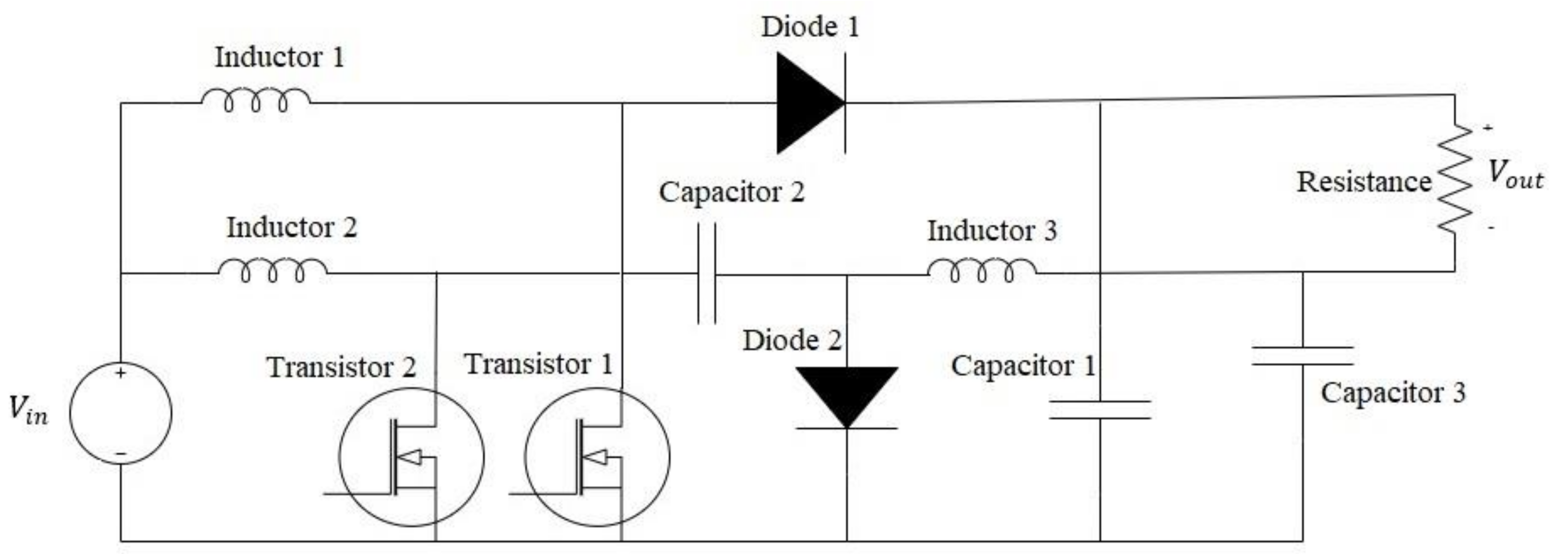
2. System Description: Hybrid Interleaved Converter

This section introduces the configuration and system description of the hybrid interleaved boost–Cuk converter considered in this article. Figure 1 presents the hybrid converter under study as presented in [6,7]. The hybrid converter consists of the classical Cuk and conventional Boost converters. In the hybrid converter, the power switches and input source are designed in the same way for both Cuk and Boost converters. Hence, both converters (Cuk and Boost) have the same input voltage and the output of the Cuk is connected to the load and then to the boost converter, as shown in Figure 1. In addition, the Cuk side generates a negative level of output voltage compared to the Boost. Therefore, the voltage gain with the hybrid interleaved boost–Cuk is larger than with two Boost converters. As previously discussed, and presented in [6,7], the hybrid converter can be operated with different duty cycles for the Cuk and Boost converters giving an additional degree of freedom to the hybrid converters.
The optimal performance can be selected by choosing the optimal duty cycles that provide input current ripple and are equal to zero [6,10,11,12,13]. The input current ripple of the hybrid converter is dependent on different variables such as the input voltage, inductance, inductors current, and capacitors’ voltage. In general, the design and operation of the hybrid converter are well-presented in the literature [6,7], the hybrid converter’s voltage and current output are straightforwardly expressed as follows [6,10]:
V o u t = V i n 1 1 d 1 + V i n d 2 1 d 2
i o u t = V o u t r
where V o u t and V i n are the output and input voltages, respectively; and d 1 and d 2 are the duty cycle of transistors 1 and 2, respectively. The output current, i o u t , is calculated based on the load resistance r. In the PWM strategy presented in [6] for the hybrid converter, the duty cycle of the converter for transistor 2 is assigned as d = d 2 , and the duty cycle of transistor 1 is considered as d 1 = k d , where k is a duty-cycle-based factor. The factor k is determined from the duty cycle where the input current ripple is equal to zero, d 0 , and this relationship is calculated by
k = 1 d 0 d 0
This paper aims to investigate the operation of the hybrid converter based on the PWM strategy [6,10,11,12,13], in which the hybrid converter can choose the ripple current equal to zero for the duty cycle. In order to find the optimal duty cycle d and the factor k, an objective function is presented and used [6,7] to minimize the input current ripple. The current ripple, i r i p , for both possible cases ( d > d 0 and d < d 0 ) can reach a maximum value within two different periods ( 1 d T s and 1 k d T s , as described in the following equations. The i r i p 1 and i r i p 3 will be during the period 1 d T s and i r i p 2 and i r i p 4 will be during the period 1 k d T s [6,10,11,12,13].
i r i p 1 = V i n T s l 2 k l 1 d k l d , d > d 0
i r i p 2 = V i n T s l 2 k l k l k d k l k d , d > d 0
i r i p 3 = V i n T s l 2 k l k d 1 d k l d , d < d 0
i r i p 4 = V i n T s l 2 k l d 1 k d k l k d k l k d , d < d 0
where T s is the switching period for transistors and is equal to the inverse of the switching frequency f s w ; k l is a factor determined based on the ratio between the values of inductor 1 l 1 and inductor 2 l 2 in the circuit. In order to minimize the highest input current ripple, an objective function is designed in this work [6,7] by considering the operational cases ( d > d 0 and d < d 0 ), as described in Equation (8).
m i n       f d , k d , k                                       = f 1 d , k   ,                                     d > d 0 f 2 d , k ,                     o t h e r w i s e
where f 1 d , k and f 2 d , k are described as follows:
f 1 d , k = i r i p 2 , i r i p 2 > i r i p 1 i r i p 1 ,   o t h e r w i s e
f 2 d , k = i r i p 4 , i r i p 4 > i r i p 3 i r i p 3 ,   o t h e r w i s e
subject to
0 < d < 1
0 < k < 1
g 1 1 k d + d 1 d g + t
where g is the desired voltage gain and t is the permissible tolerance (t is considered as 1% of g ). In addition, a penalty function presented by [6] is employed in this work to guide the search for feasible solutions.

3. The Proposed Optimization Algorithms

Optimal operation of the hybrid interleaved boost–Cuk converter requires the minimization of input current ripple by selecting the optimal duty cycle. As described in Section 2, there are two operation cases under different switching periods. The objective function, as described in Equation (8), is designed to minimize the highest input current ripple by considering the operational cases ( d > d 0 and d < d 0 ). In addition, the proposed optimization process, as shown in Section 2, includes a number of constraints related to the desired voltage gain, switching time, and the permissible values of d and k. Modern optimization algorithms—namely, MRFO [12], MPA [14], JS [13], and EO [15]—are developed and employed in this work to find and achieve the optimal general duty cycle, d, and the optimal value of the factor k. The proposed modern optimization algorithms solve the complex optimization problem for the hybrid converter in the simplest way with a low computational cost.

3.1. Equilibrium Optimizer (EO)

The Equilibrium Optimizer (EO) was proposed by Faramarzi et al. [15]. The EO is inspired by the control volume mass balance model. The EO algorithm utilizes the estimation process for both the dynamic and equilibrium states as inspiration to find an optimal solution. The EO algorithm is compared to 58 benchmarked functions in [15] and compared to common and recent methods such as Genetic Algorithm (GA) and Particle Swarm Optimization (PSO) methods. The results showed that the EO achieved high performance and outperformed the common methods for all 58 optimization functions. In EO, the search area is randomly generated to solve the objection function, as shown in Equation (14).
p s i n i t i a l = p m i n + r s p m a x p m i n
where p s i n i t i a l is the initial generation vector for the s t h particle ( s = 1 , 2 , 3 , , k ), p m a x and p m i n are the maximum and minimum dimensions, r s is a random vector, and k is the number of particles in the population. The search area is updated with respect to the best solution location, where each particle (solution) is connected to a position and acts as a search agent based on exponential term q and random vector λ in the interval [0,1] at time t , as presented in Equation (15). In order to control the exponential term q , the constant term z 1 is used. The direction of searching (exploration and exploitation) is also affected by the s i g n   c 0.5 , where c is a random vector between [0,1]. The updated searching position of each particle p is presented by Equation (16).
q = z 1 s i g n c 0.5 e λ t 1
p = p e q + p s p e q   q + H j B 1 q
where p s is the generation vector for the s t h particle and p e q is the best solution location. In order to achieve a global search process, the H j B 1 q is applied based on turnover rate ( j ), the exponential term ( q ), and the generation rate ( H ) , and B is considered as a limitation unit. In the EO algorithm, the particles (solutions) are similar to the position of particles in PSO. The EO uses the mass balance equation (cost function) to present the physical process of controlling the mass, which involves finding the optimal solution and determining the next moving step. The EO algorithm showed a powerful performance and outperformed the different standard and advanced algorithms in [15] over different optimization and engineering problems.

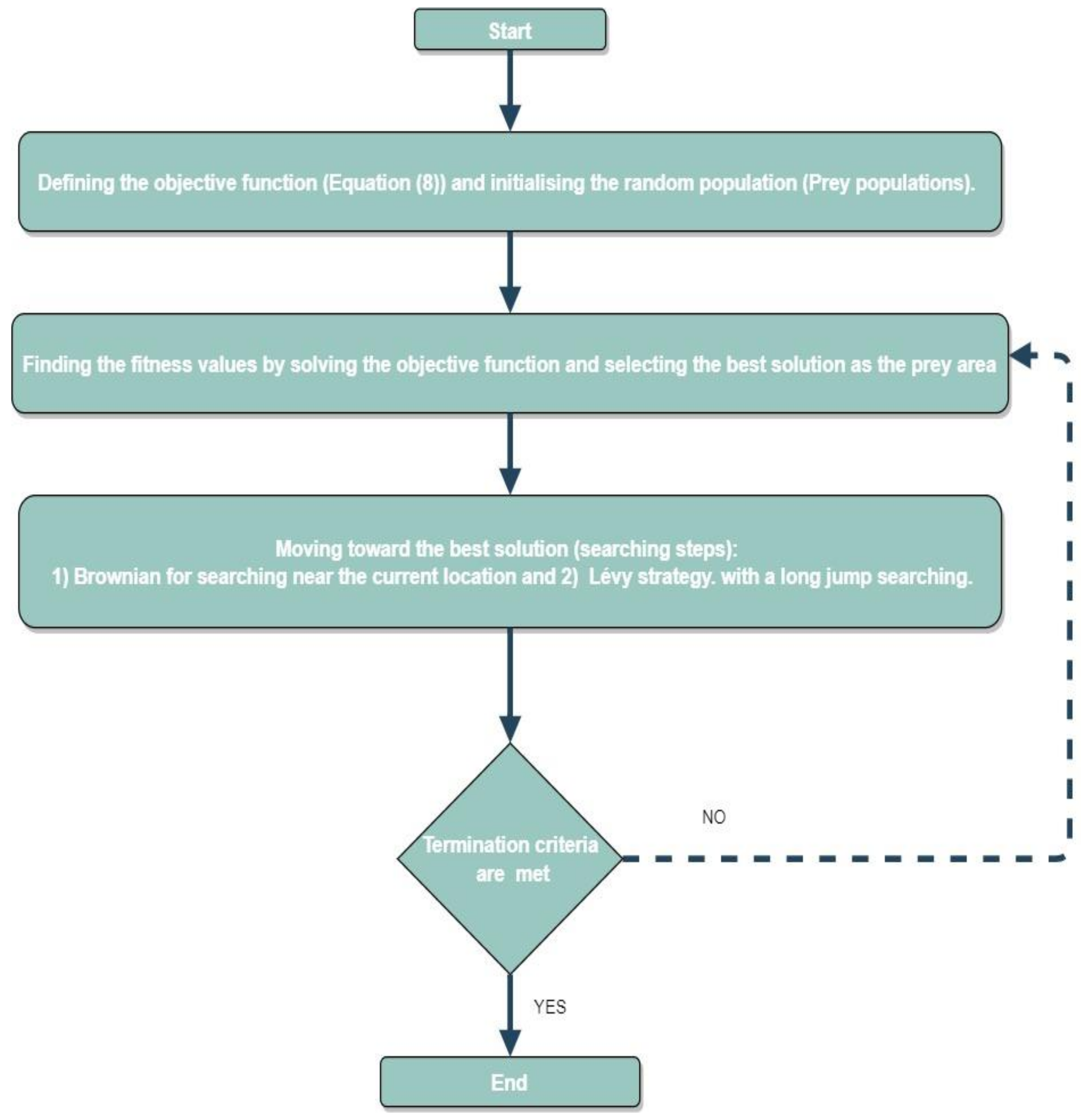
3.2. MRFO, JS, and MPA Algorithms

The Manta Ray Foraging Optimization (MRFO), Marine Predators Algorithm (MPA), and Jellyfish Search (JS) are bioinspired metaheuristic optimization algorithms. MRFO was proposed by Weiguo Zhao et al. [12] in 2019 and MPA and JS were proposed by Faramarzi et al. [14] and Chou and Truong [13] in 2020, respectively. MRFO algorithm applies the intelligent activities and movements of manta rays to find food as the inspiration to find an optimal solution through three strategies, namely, chain, cyclone, and somersault. Figure 2 shows the solving optimization problem process for the MRFO algorithm. In MRFO, the initial population and search area with M size of the population are randomly generated based on Equation (17).
p i t = p l + r a n d p u p l ,   i = 1 , , M
where p i t is the initial generation vector for the t iteration, p u ,   p l are the upper and lower dimensions of the problem space. Then, the fitness of each individual is calculated based on a determined cost function f, as follows:
f i = f p i
Then, the search area is updated with respect to the best solution location ( p b e s t ) and the rand value. If the rand value is less than 0.5, the cyclone foraging technique is used, as presented in Equation (19). Otherwise, the chain foraging technique is used as shown in Equation (20).
p i t + 1 = p r a n d + r p r a n d p i t + β p r a n d p i t       f o r   i = 1 p r a n d + r p i 1 p i t + β p r a n d p i t       f o r   i = 2 , , N
p i t + 1 = p i t + r p b e s t p i t + α p b e s t p i t       f o r   i = 1 p i t + r p i 1 p i t + α p b e s t p i t       f o r   i = 2 , , N
where α and β are weight coefficients; r is rand number in [0,1]; and p r a n d is a random position, which is randomly produced in the space. This process will be repeated until the maximum iteration is achieved.
The basic idea of MPA and JS are also inspired by the intelligent movements of ocean predators and jellyfish, respectively, to create foraging strategies. The JS algorithm is motivated by the behaviour of jellyfish [13]. The natural movements of jellyfish in the ocean, which are divided into current motions and swarm motions, are described as the basic moves to achieve the optimal solution using JS algorithm. In addition, the JS algorithm includes a time control mechanism to switch between these movements until it achieves the optimal solution. The main steps for solving optimization problems by using the JS algorithms can be summarized as follows [13]:
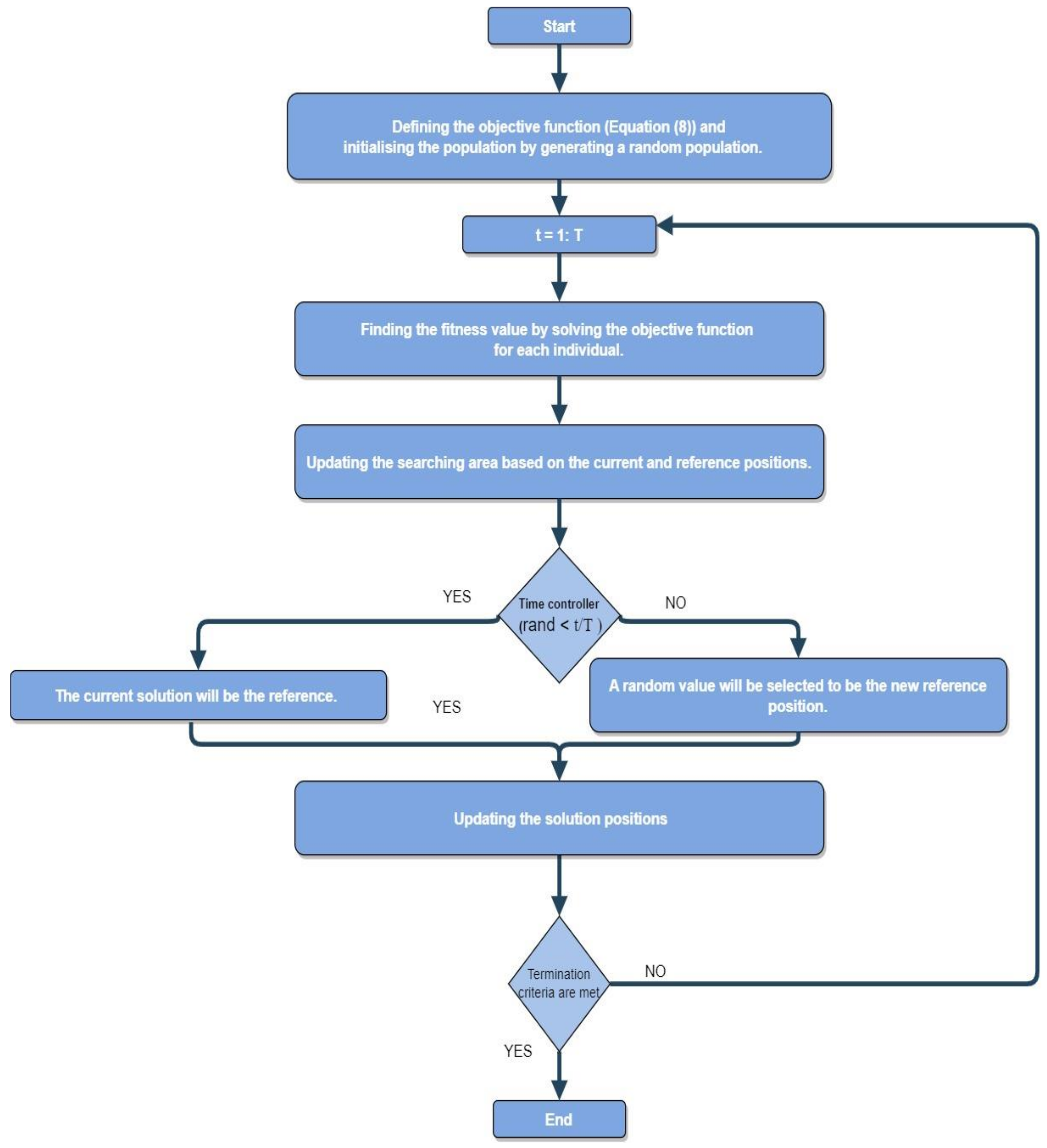
  • Step 1: Defining the objective function and initialising the population: the cost function needs to be selected in this step, Equation (8). In addition, the size of the population and number of iterations need to be selected to generate a random population (solution) within the domain.
  • Step 2: Determining the food quantities for the jellyfish. In this step, the searching process is started. At each iteration, the objective function is solved as a fitness function for the population; then, the best location (solution) is selected as the reference position.
  • Step 3: Searching step under a time control mechanism: the moving strategy towards the next step to finding the optimal solution depends on the algorithm’s inspiration (jellyfish movement). However, individuals in the population will be updated at each iteration based on the current position and the best position for the population. Here, for each iteration, a time control function is determined as a random value between 0 and 1 to regulate the searching process. The time control function value is compared to the constant value and if the time control value is larger than the constant time value, the ocean current moves are determined the next step move; otherwise, the swarm motions will take the lead to select the next movement.
  • Recalculate the quantity of food (cost function value) by solving the objective function at the new position and determine the best location where most of the food (best objective function result) is available. Here, the iteration will be updated.
  • Step 4: Previous steps are repeated by recalculating the quantity of food (solving cost function value with the new solving position) until the maximum number of iterations is achieved.
The basic idea of MPA is inspired by the intelligent movements of ocean predators to create foraging strategies [14]. The main steps for solving optimization problems by using the MPA algorithm are summarized in Figure 3. Firstly, the search domain, which is uniformly distributed, will be chosen based on Brownian motion for the prey. Secondly, to move towards the optimal solution, the new position will be selected as the minimum value of the fitness function (cost function). Then, the new position will replace the previous solution. Here, the two searching strategies will be used (predator and prey locations) to achieve the optimal solution with minimum movement and time. Finally, the previous process will be repeated until the maximum number of iterations is achieved. In MPA, the initial population p O is randomly generated based on Equation (21).
p O = p m i n + r a n d p m a x p m i n
where p m a x and p m i n are the upper and lower bound for the variables in the problem space, and the rand is a random vector in the range of [0,1]. Then, the fitness of each individual will be calculated based on a determined cost function. The search area is updated with respect to the best solution location and velocity ratio. If the velocity ratio is more than 10, phase 1 is used, as presented in Equation (22). During phase 1, the prey technique is applied with fast movement compared with the predator action. In this case, the best action for the predator is to stay constant (not moving).
S i = r n ( E i r n   P r e y i ) P r e y i = P r e y i + P · r   · S i
where S i is the step size move, E i is the fittest solution and called Elite matrix, P r e y i is the Prey matrix, r n is the vector of random numbers, r is vector random numbers within [0,1], and P is a constant value. In case the velocity ratio is less than 10, phase 2 is used, as presented in Equation (23). In this phase, the predator and prey movements are applied; further, the transition from exploration to exploitation will occur.
S i = r z   ( E i r z   P r e y i ) P r e y i = P r e y i + P · r   · S i
where r z is random numbers vector based on Levy distribution. This process will be repeated until the maximum iteration is achieved.
Overall, the main aim of these modern optimization algorithms is to provide a powerful and alternative optimization approach for solving complex engineering problems with a lower running simulation time. In general, the MRFO, MPA, and JS have a smaller number of adjustable parameters compared with common optimization algorithms such as DE and PSO [6]. The proposed modern algorithms (MRFO, MPA, and JS) showed powerful performance and outperformed common algorithms in [1,4] over different optimization and engineering problems.

4. Simulation Results and Discussion

The main aim of the optimal control strategy is to minimize the highest input current ripple under different operation cases. Firstly, the description of the experimental setup and the parameters of the optimization algorithms are presented in this section. Secondly, the performance of the modern optimal control strategies is compared with common algorithms from the literature in terms of the minimum input current ripple and convergence. Finally, the proposed modern optimal controller is evaluated and tested under various input voltage V i n , switching frequency f s w , and inductor value l 2 . The main test setup parameters for the hybrid interleaved boost–Cuk converter is presented in Table 1. The hybrid interleaved boost–Cuk converter under study, as shown in Figure 1 and Table 1, is proposed and developed as in [6,7]. This hybrid converter is a common and standard model, which will help to compare the results with the literature. Firstly, to evaluate the robustness of the proposed modern optimization strategies, the results in the following section have been considered under different desired voltage gain g , ranging from 3 to 6. The parameters l 2 ,   V i n , and f s w are used to evaluate the performance of the proposed modern strategies. In this paper, the main parameters and configuration of the proposed and common optimization algorithms are chosen and selected as the optimal values for each one, as presented in Table 2.
Table 1. The main parameters of the hybrid interleaved boost–Cuk converter model.
ParameterValue
V i n 20 volts
d 0 0.6
f s w 50 kHz
l 2 100 µH
l 1 66 µH
k l 0.6666
r60 Ω
Table 2. The main parameters of the optimization algorithms.
AlgorithmParametersOptimal ValueTesting Range
PSO [6,7]Inertia coefficient inertiaDecreasing from 0.9 to 0.4 (linearly)-
Number of search agents5025–100
Maximum number of iterations10050–200
Acceleration coefficient1 and 2-
DE [6,7]Weight factorRandomly selected (0.2 to 0.8)-
Recombination probability0.20.1–0.4
Constant factor105–20
Size of population5025–100
Maximum number of iterations10050–200
MRFO [12]Search agents number5025–100
Initial gravitational constant10050–150
Size of population5025–100
Maximum iteration number10050–200
JS [13]Size of population5025–100
Maximum iteration number10050–200
EO [15]Number of search particles5025–100
Maximum number of iterations10050–200
Generation probability0.5-
Constant values for controlling exploration (a1)2-
Constant values for controlling exploitation (a2)1-
MPA [14]Size of population 5025–100
Maximum iteration number10050–200

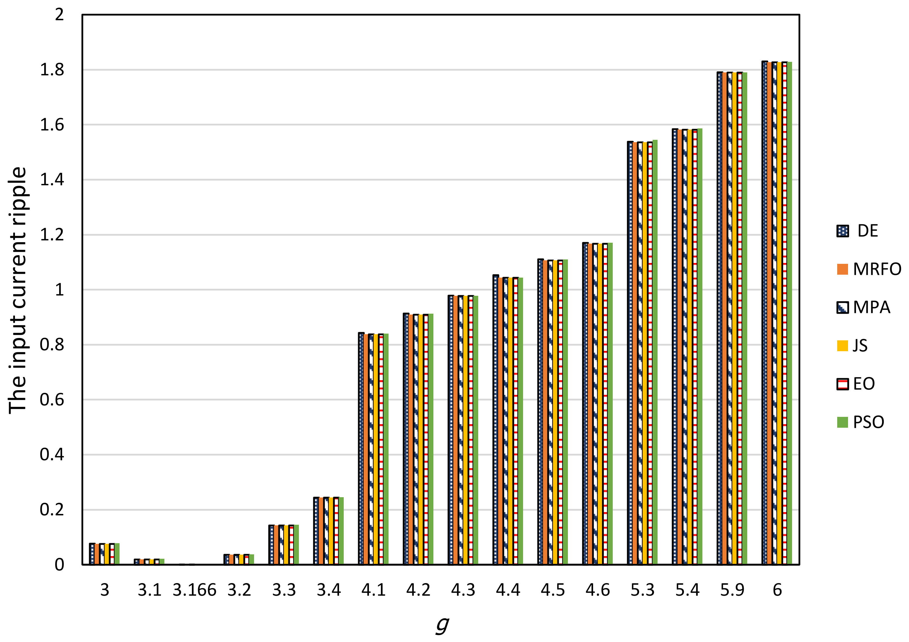
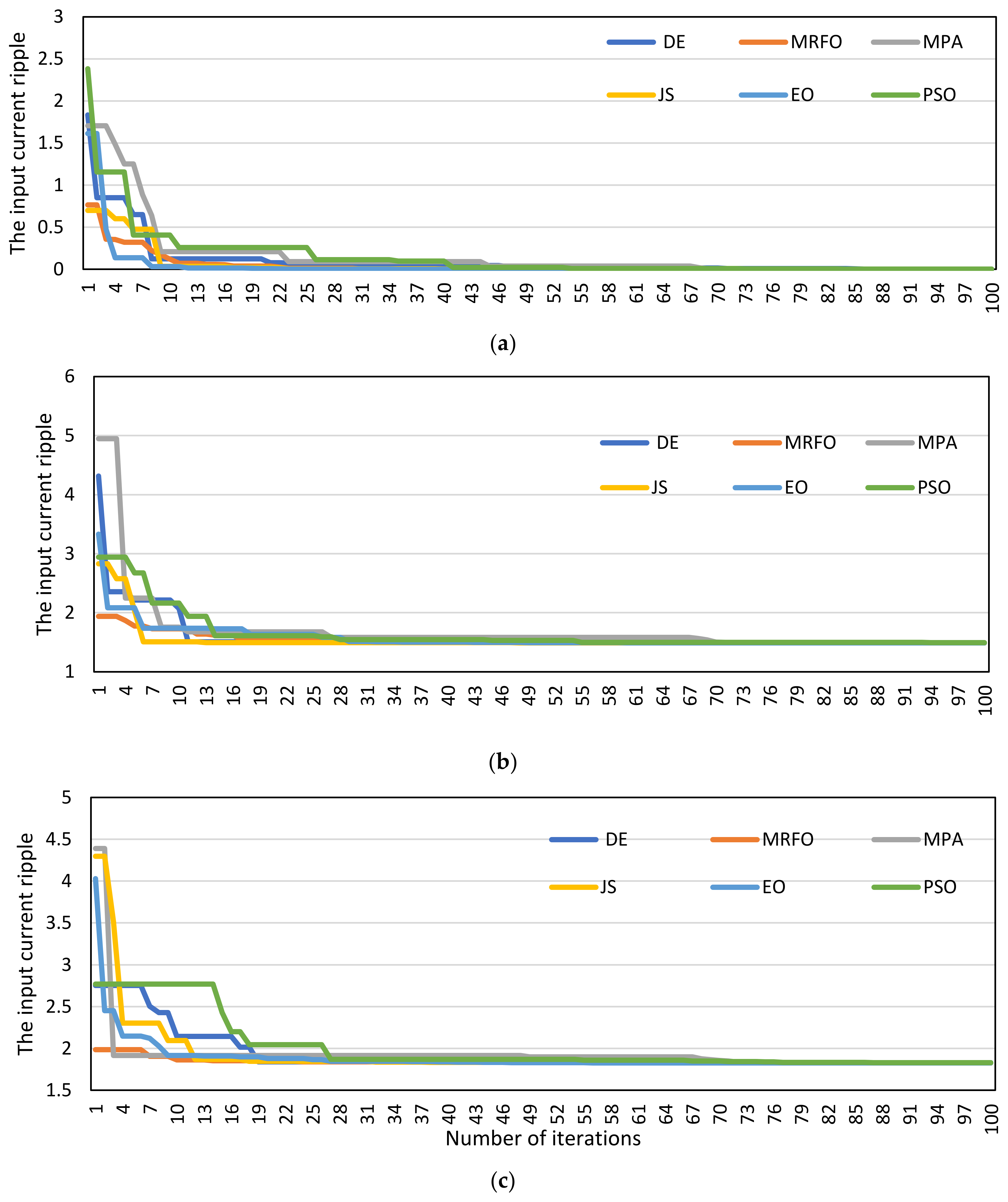
4.1. Comparative Performance Evaluation

The results obtained from the proposed and common optimization algorithms for the presented hybrid interleaved boost–Cuk converter model is presented in Table 3. The performance of the optimization algorithms is evaluated by using different desired voltage gains g . The main aims of controlling the voltage gain are to achieve the desired output voltage and then the minimum ripple current. In general, the proposed modern optimization algorithms (MRFO, MPA, EO, and JS) outperform the common optimization algorithms (DE and PSO) by achieving the minimum input current ripple i r i p in all simulations. In addition, the proposed modern optimization algorithms provided the highest balance level in power-sharing compared with the common algorithms [6]. For example, the current ripple at g equal to 4.2 V and 4.8 V was reduced by 8.499% and 7.622% in JS method compared with [6], respectively. The modern optimization methods achieve lower input current ripple and higher control performance, as evident in Table 3. The summary of the results is presented in Figure 4 by comparing the values of input current ripple overall operational scenarios. The lowest input current ripple was achieved for all optimization algorithms by using the voltage gain g equal to 3.166 V. In general, the input current ripple value for all algorithms increases with the increase in the voltage gain value, g , for values greater than 3.166 V.
Table 3. Comparative performance in terms of the reduction percentage in ripple current for the proposed and common control strategies compared with [6] with different desired voltage gains g .
Optimization Method g %Reduction g %Reduction g %Reduction g %Reduction
DE4.2−8.07064.8−7.295975.2−1.487976−1.48797
MRFO−8.49989−7.62114−1.49299−1.49299
MPA−8.49931−7.6219−1.49334−1.49334
JS−8.49989−7.62208−1.49336−1.49336
EO−8.49961−7.62197−1.49336−1.49336
PSO−8.16299−7.46834−1.45342−1.45342
In order to evaluate the proposed modern optimization controllers and compare them with the common algorithms, convergence curves for three cases ( g = 3.166, 4.4, and 6 V) are presented in Figure 5. Convergence curves present the relationship between the generations (iterations) and the value of the input ripple current. These curves help in investigating the speed of optimization algorithms to achieve the optimal solution. Figure 3 shows that the modern optimization algorithms (MRFO, MPA, EO, and JS) generate smoother convergence curves and exhibit speedier responses compared with the common optimization algorithms (DE and PSO). The results in Figure 3 present the modern optimization algorithms (MRFO, MPA, EO, and JS) as more efficient and powerful algorithms compared with DE and PSO [6,7] in terms of computational cost.

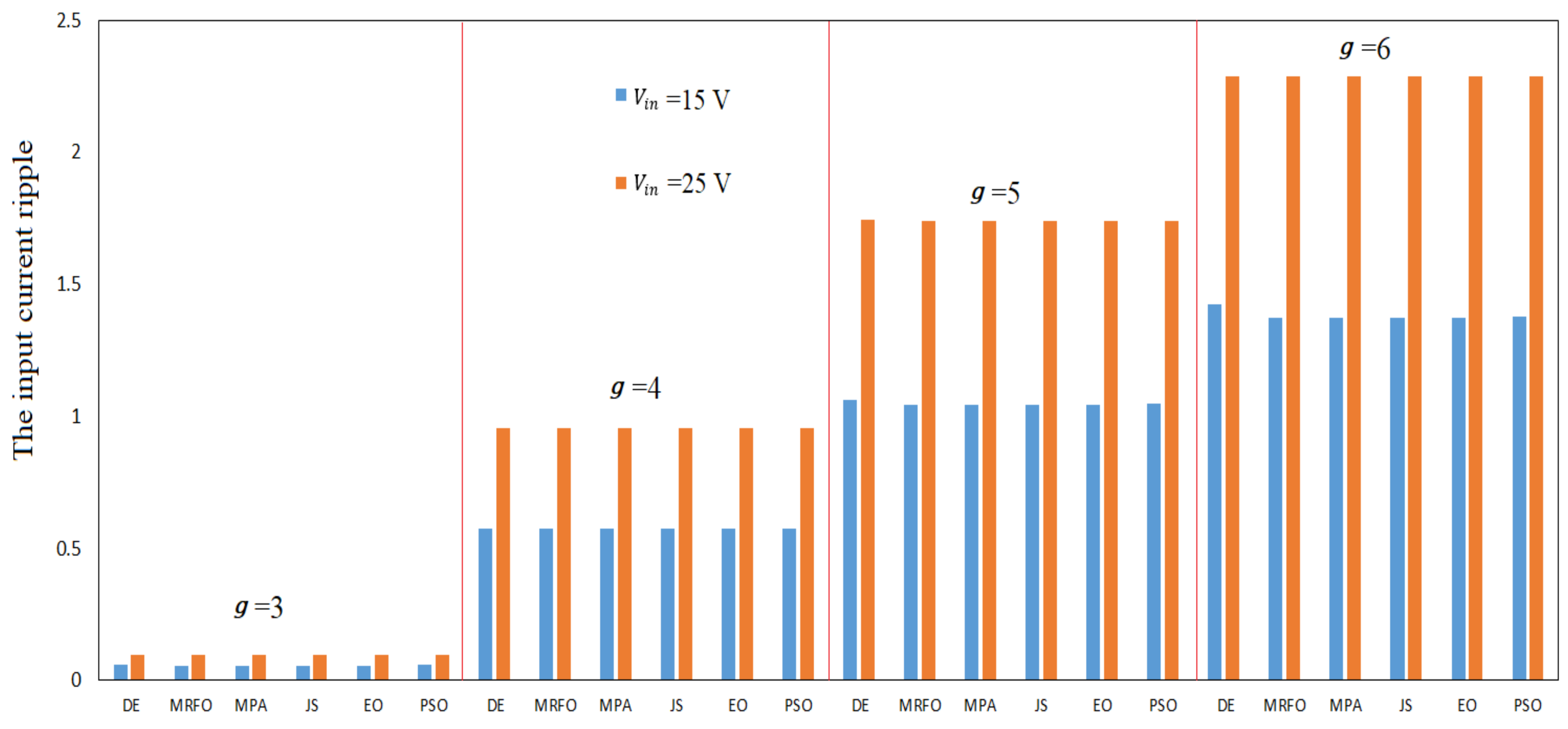
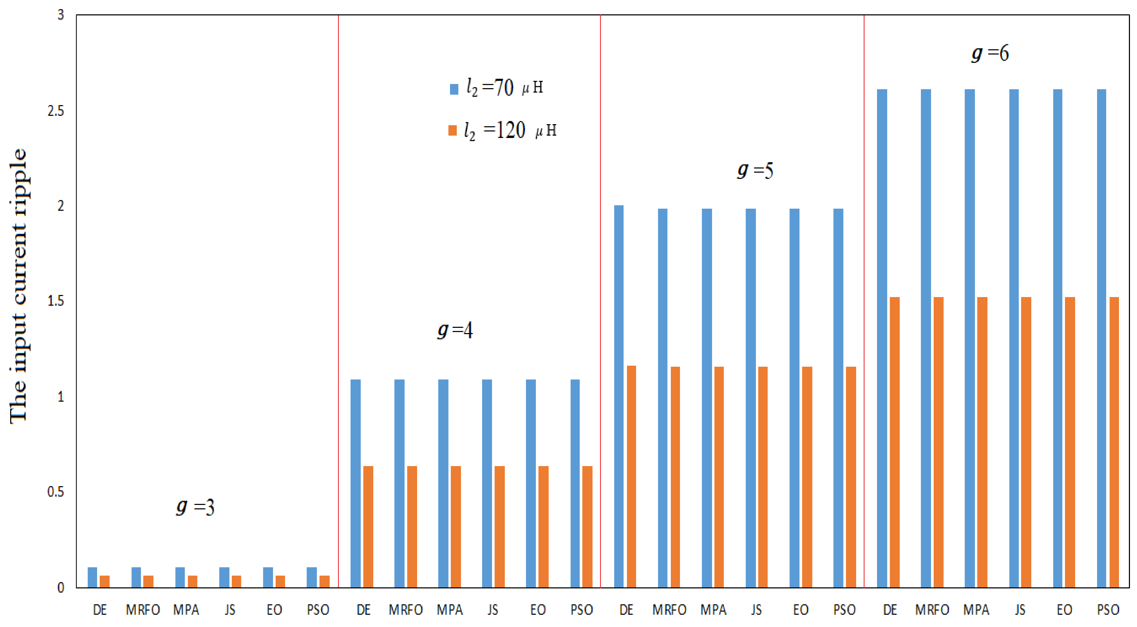
4.2. Comparative Performance Based on Different l2, Vin, and fsw

This section discusses the impact of the parameters of the hybrid interleaved boost–Cuk converter ( l 2 ,   V i n , and f s w ) on the input current ripple and the modern optimal strategies for different operation scenarios. Figure 6 presents the results of the modern and common optimization algorithms over four operation cases ( g = 3, 4, 5, and 6 V) with two inductance values, l2 = 70 µH and 120 µH. The results in Figure 6 showed that the increment in the value of l2 will lead to a reduction in the input current ripple, as also described by Equations (4)–(7), for all algorithms. It can also be noticed from Figure 4 that the proposed modern optimization algorithms outperformed the common DE and PSO algorithms in all operational scenarios with different inductor values.
Figure 7 presents the impact of the input voltage Vin of the hybrid interleaved boost–Cuk converter on the input current ripple. The results of the modern and common optimization algorithms over different voltage gains and two input voltage values, Vin = 15 V and 25 V, are presented in Figure 7. The results show that the increment of the input voltage Vin will lead to an increment in the input current ripple, as also described by Equations (4)–(7), for all algorithms. It is also observed that the proposed MRFO, MPA, EO, and JS algorithms outperformed the DE and PSO in all operational scenarios with different input voltage values. Table 4 presents the impact of the switching frequency fsw on the input ripple current under the performance of the proposed modern and common optimization techniques. The experimental results for the hybrid interleaved boost–Cuk converter over different operational cases with fsw = 40 kHz and 60 kHz are presented in Table 4. The results of hybrid interleaved boost–Cuk converter over different operational cases show that the increase in fsw from 40 kHz to 60 kHz decreases the input current ripple for all algorithms by 33%.

4.3. Power Losses Anaylsis

The total power losses are calculated and presented in Table 5 for different input voltages g. The total power loss values for all the proposed optimization algorithms outperformed the common control model in [6]. The results clearly show that the proposed optimization algorithms approximately reduced the power loss compared with [6] by 56.6%, 55.8%, and 51.5% for g equal to 4.8, 5.2, and 6 V, respectively. By comparing the power loss at different voltage gains, the power loss is increased with the increasing voltage gain. In addition, the results showed that the proposed MRFO, MPA, EO, and JS algorithms outperformed those in [6], DE, and PSO in all operational scenarios with different input voltage values. In addition, the efficiency results obtained from the proposed optimization algorithms and common controller [6] under different desired voltage gains, g . The total efficiency for the hybrid interleaved boost–Cuk converter model has been improved by using the proposed optimization algorithms compared with the common control model in [6]. For example, the DE method improved the efficiency to 98% compared with [6] with 96.03% at g equal to 6, as shown in Table 6.
Table 5. The power losses of the proposed modern and common [6] optimal strategies under different desired voltage gains g .
Optimization Method g Power Loss (W) g Power Loss (W) g Power Loss (W)
[6]4.82.4108925.24.30793569.93078
DE1.0418981.9504034.903349
MRFO1.044091.9477154.808277
MPA1.0440431.9474544.80842
JS1.0440291.9474454.807922
EO1.0440351.9474454.807924
PSO1.0630081.9884814.852875
Table 6. The total efficiency of the proposed modern and common [6] optimal strategies under different desired voltage gains g .
Optimization Method g Efficiency g Efficiency g Efficiency
[6]4.898.45%5.297.67%696.03
DE99.33%98.93%98.00%
MRFO99.32%98.93%98.04%
MPA99.32%98.93%98.04%
JS99.32%98.93%98.04%
EO99.32%98.93%98.04%
PSO99.31%98.91%98.02%

5. Conclusions

This work presented modern optimization algorithms with PWM strategy for the hybrid interleaved boost–Cuk converter. The proposed MRFO, MPA, EO, and JS algorithms were employed to achieve the minimum input current ripple by finding the optimal duty cycle. The robustness of the proposed algorithms was evaluated through the performance of the hybrid interleaved boost–Cuk converter under different parameter values for the inductor, voltage, and switching frequency. The proposed optimization algorithms (MRFO, MPA, EO, and JS) outperformed the standard and common algorithms from the literature: PSO and DE. The results show that the proposed optimization algorithms achieve lower input current ripple under different operation scenarios with different voltage gains. Furthermore, the proposed algorithms provided a higher balance level of power-sharing based on the minim ripple current and a lower computational cost compared with DE and PSO. The robustness of the proposed algorithms was evaluated through the performance of the hybrid interleaved boost–Cuk converter under different parameter values for the current, voltage, and switching frequency.

Author Contributions

Conceptualization, F.A. and K.N.; methodology, K.N., F.A., and W.H.; software, K.N. and F.A.; validation, K.N. and F.A.; formal analysis, A.V., A.A., W.H., and F.A.; investigation, K.N. and F.A.; resources, all authors; data curation, all authors; writing—original draft preparation, F.A. and K.N.; writing—review and editing, all authors; visualization, all authors; supervision, all authors; project administration, F.A. and K.N. All authors have read and agreed to the published version of the manuscript.

Funding

This research received no external funding.

Acknowledgments

We would like to thank the Renewable Energy Center at The Hashemite University for their support.

Conflicts of Interest

The authors declare no conflict of interest.

References

  1. Alasali, F.; Nusair, K.; Obeidat, A.; Foudeh, H.; Holderbaum, W. An analysis of optimal power flow strategies for a power network incorporating stochastic renewable energy resources. Int. Trans. Electr. Energy Syst. 2021, 31, e13060. [Google Scholar] [CrossRef]
  2. Alomoush, M. Microgrid combined power-heat economic-emission dispatch considering stochastic renewable energy resources, power purchase and emission tax. Energy Convers. Manag. 2019, 200, 103300. [Google Scholar] [CrossRef]
  3. Pietrosanti, S.; Alasali, F.; Holderbaum, W. Power management system for RTG crane using fuzzy logic controller. Sustain. Energy Technol. Assess. 2020, 37, 100639. [Google Scholar] [CrossRef]
  4. Nusair, K.; Alasali, F.; Hayajneh, A.; Holderbaum, W. Optimal placement of FACTS devices and power-flow solutions for a power network system integrated with stochastic renewable energy resources using new metaheuristic optimization techniques. Int. J. Energy Res. 2021, 45, 18786–18809. [Google Scholar] [CrossRef]
  5. Alasali, F.; El-Naily, N.; Zarour, E.; Saad, S.M. Highly sensitive and fast microgrid protection using optimal coordination scheme and nonstandard tripping characteristics. Int. J. Electr. Power Energy Syst. 2021, 128, 106756. [Google Scholar] [CrossRef]
  6. Rodríguez, A.; Alejo-Reyes, A.; Cuevas, E.; Beltran-Carbajal, F.; Rosas-Caro, J.C. An evolutionary algorithm-based PWM strategy for a hybrid power converter. Mathematics 2020, 8, 1247. [Google Scholar] [CrossRef]
  7. Arias-Angulo, J.P.; Rosas-Caro, J.C.; Beltran-Carbajal, F.; Valderrabano-Gonzalez, A.; Haro-Sandoval, E.; Gutierrez-Alcala, S.; Alejo-Reyes, A.; Garcia-Vite, P.M. Power quality improvement by interleaving unequal switching converters. IEICE Electron. Express 2016, 13, 20160558. [Google Scholar]
  8. Erickson, R.W.; Maksimovic, D. Fundamentals of Power Electronics, 2nd ed.; Kluwer: New York, NY, USA, 2001. [Google Scholar]
  9. Banerjee, S.; Ghosh, A.; Rana, N. An Improved interleaved boost converter with PSO-based optimal type-III controller. IEEE J. Emerg. Sel. Top. Power Electron. 2017, 5, 323–337. [Google Scholar] [CrossRef]
  10. Laoprom, I.; Tunyasrirut, S. Design of PI controller for voltage controller of four-phase interleaved boost converter using particle swarm optimization. J. Control Sci. Eng. 2020, 2020, 9515160. [Google Scholar] [CrossRef] [Green Version]
  11. Mohd-Rashid, M.I.; Hiendro, A.; Anwari, M. Optimal HE-PWM inverter switching patterns using differential evolution algorithm. In Proceedings of the 2012 IEEE International Conference on Power and Energy (PECon), Kota Kinabalu, Malaysia, 2–5 December 2012; pp. 32–37. [Google Scholar]
  12. Zhao, W.; Zhang, Z.; Wang, L. Manta ray foraging optimization: An effective bio-inspired optimizer for engineering applications. Eng. Appl. Artif. Intell. 2020, 87, 103300. [Google Scholar] [CrossRef]
  13. Chou, J.; Truong, D. A novel metaheuristic optimizer inspired by behavior of jellyfish in ocean. Appl. Math. Comput. 2020, 389, 125535. [Google Scholar] [CrossRef]
  14. Faramarzi, A.; Heidarinejad, M.; Mirjalili, S.; Gandomi, A. Marine predators algorithm: A nature-inspired metaheuristic. Expert Syst. Appl. 2020, 152, 113377. [Google Scholar] [CrossRef]
  15. Faramarzi, A.; Heidarinejad, M.; Stephens, B.; Mirjalili, S. Equilibrium optimizer: A novel optimization algorithm. Knowl.-Based Syst. 2020, 191, 105190. [Google Scholar] [CrossRef]
Figure 1. The hybrid interleaved boost–Cuk converter.
Electronics 11 02019 g001
Figure 2. The MRFO algorithm procedures.
Electronics 11 02019 g002
Figure 3. The MPA procedures.
Electronics 11 02019 g003
Figure 4. The comparison of the input current ripple modern strategy results in different operation scenarios for voltage gains g ranging from 3 to 6.
Electronics 11 02019 g004
Figure 5. The comparison of the convergence results modern strategy for different operation scenarios (a) g = 3.166 V, (b) g = 4.4 V, and (c) g = 6 V.
Electronics 11 02019 g005
Figure 6. The impact of inductance l2 on the performance of the proposed modern and common optimal strategies under different desired voltage gains g .
Electronics 11 02019 g006
Figure 7. The impact of input voltage Vin on the performance of the proposed modern and common optimal strategies under different desired voltage gains g .
Electronics 11 02019 g007
Table 4. The impact of switching frequency f s w on the performance of the proposed modern and common optimal strategies under different desired voltage gains g .
Optimal Algorithms g irip at fsw = 40 kHzirip at fsw = 60 kHzDecreasing %
DE30.096770.06502632.80%
MRFO0.0945530.06303633.33%
MPA0.0945570.06303633.33%
JS0.0945530.06303533.33%
EO0.0945540.06305833.33%
PSO0.0963010.0645233.31%
DE40.9564060.63798933.29%
MRFO0.9548380.63655933.33%
MPA0.954840.63656133.33%
JS0.9548380.63655933.33%
EO0.9548380.63663533.33%
PSO0.9559220.63749733.32%
DE51.7390141.16296333.12%
MRFO1.7370551.15803633.33%
MPA1.7370551.15803933.33%
JS1.7370531.15803633.33%
EO1.7370591.15803633.33%
PSO1.737681.16394433.30%
DE62.2867611.53034533.30%
MRFO2.2845091.523043.33%
MPA2.2845581.5230093.33%
JS2.2845121.5230083.33%
EO2.2845091.5230063.33%
PSO2.2862321.5302533.30%
Publisher’s Note: MDPI stays neutral with regard to jurisdictional claims in published maps and institutional affiliations.

