Abstract
The high-frequency (HF) square-wave voltage injection method can be used in permanent magnet synchronous motor (PMSM) drive systems. However, when the switching frequency is too low, the injection frequency will also decrease, which will reduce the update frequency of the HF response current, making it difficult to extract the position quadrature signal and affecting the accuracy of position estimation and control performance. This paper proposes a method for extracting position quadrature signals based on sampling rate transformation, and a signal processing strategy based on Cascade Integrator Comb (CIC) interpolation filtering, which can solve the problem of waveform distortion caused by the low sampling rate of the extracted position quadrature signal. This strategy can increase the sampling rate of the position quadrature signal to the pulse width modulation (PWM) update frequency by interpolating in the sampling current, thereby reducing the harmonic content of the position quadrature signal and improving the position estimation. precision. In addition, the PWM update frequency and estimated rotational speed information are used to compensate for the delay caused by position estimation and inverter update, which effectively improves the accuracy of position estimation. Finally, the effectiveness of the proposed control strategy is verified by simulation.
1. Introduction
Compared with the induction motor, permanent magnet synchronous motor (PMSM) has higher efficiency and higher power density, so it is widely used in high-performance applications [1,2]. In the electric traction system of rail transit, due to the harsh operating environment and the small installation position of the sensor, it is not suitable to use the position sensor to realize the closed-loop control based on PMSM. The sensorless control strategy can solve this problem [3]. Sensorless control strategies are mainly divided into two categories. One is model-based sensorless control suitable for medium and high-speed areas, and the other is sensorless control based on salient polarity suitable for zero and low speed areas [4]. As a position estimation method based on salient polarity, the high-frequency (HF) injection method can generally be divided into current injection and voltage injection according to different injection forms. Since the estimation bandwidth of rotor position is affected by the bandwidth of current controller, the application of current injection method is relatively few [5]. HF voltage injection method can be divided into indirect flux detection by online reactance measurement (INFROM) method [6], rotating sinusoidal injection method [7], pulse vibration sinusoidal injection method [8,9], pulse vibration square wave injection method [10], and pulse signal injection method [11]. The difference lies in the form and time of injection signal and the demodulation method of HF response current. In this paper, the HF voltage injection method based on saliency polarity is adopted, which can ensure a high signal-to-noise ratio and improve the stability of the control system under harsh working conditions.
In addition, for the electric traction system, in order to improve the efficiency and load-carrying capacity of the inverter and avoid excessive switching loss, the switching frequency will generally not exceed 1 kHz [12], which will limit the maximum injection frequency of the HF voltage injection method and reduce the update frequency of the estimated position, so that the rotor position estimation error increases in the range of zero and low speed, the current harmonic content increases, and the HF noise is more obvious. In order to reduce current harmonics and HF noise, the method of reducing the injection frequency avoids the more sensitive frequency range of human ears [13]. However, this method makes the frequencies of the fundamental frequency signal and the high-frequency response signal closer, which further limits the low-speed operating range and dynamic performance, and causes the neglected resistance term in the high-frequency model to affect the position estimation accuracy [14,15,16]. In addition, reducing the amplitude of the injected signal can reduce the noise amplitude [17], but it will reduce the signal-to-noise ratio and affect the accuracy of position estimation. Although the pseudo-random HF square wave voltage injection method [18], the dual-frequency random HF voltage injection method [19], and the intermittent pulse injection method [20] can reduce the noise, they all need a higher switching frequency, so that one or more injected HF signals can be inserted in multiple carrier cycles, which is not suitable for the case of low switching frequency.
In order to solve these problems and improve the position observation accuracy and control performance at low switching frequency, this paper, based on the high-frequency square wave voltage injection method, proposes a method for extracting position quadrature signals based on sampling rate transformation to avoid the use of complex modulation methods, and adopts the signal processing strategy based on the CIC interpolation filtering to solve the problem of mismatch between the update frequency of the position quadrature signal and the PWM update frequency, and suppress the HF ripple caused by the low update frequency of the position quadrature signal. At the same time, the delay compensation strategy is used to compensate for the delay caused by position estimation and inverter update, which effectively improves the accuracy of position estimation. Finally, the performance of the proposed strategy is analyzed by simulation.
2. Sensorless Control Strategy at Low Switching Frequency
The voltage equation of PMSM in d-q rotating coordinate system is [21,22]:
where udq, idq and Ldq are stator voltage, stator current and stator inductance in d-q rotating coordinate system respectively; Rs is the stator resistance; ωe is the electrical angular velocity; p is differential operator, p = d/dt; Ψf is the flux linkage.
In the HF-response model, because the injected square wave voltage signal frequency is higher than the motor operating frequency, the induced voltage drop of the inductance in the motor winding is greater than that of the resistance. In order to facilitate subsequent analysis and calculation, the voltage drop on the stator, the voltage drop of the inductance and the back EMF can be ignored. The HF mathematical model of PMSM can be simplified as follows:
where usd and usq are the HF voltage components in the d-q rotating coordinate system respectively; idh and iqh are the HF response current components in d-q rotating coordinate system respectively.
The square wave voltage injection method is to inject a square wave voltage signal into the estimated d-axis, so that the motor winding can excite HF response current containing rotor position information. Generally, the injection method can be divided into discontinuous pulse injection form and continuous pulse injection form according to the control cycle and whether the injection cycle is continuous. The schematic diagram is shown in Figure 1.
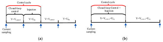
Figure 1.
Different voltage injection forms. (a) Schematic diagram of discontinuous pulse injection; (b) Schematic diagram of continuous pulse injection.
The discontinuous pulse injection strategy realizes position estimation in the injection cycle and closed-loop control in the control cycle. This method can reduce the injected frequency and noise, reduce the influence of harmonics on position estimation, improve the signal-to-noise ratio, and improve the accuracy of position solution without adding filters [18].
However, the discontinuous pulse injection strategy needs to make the switching frequency much greater than the operating frequency, so as to reduce the excessive current disturbance caused by switching and inserting a discontinuous injection HF signal in multiple control cycles. At low switching frequency, discontinuous signal injection increases the interval of injected waveform, resulting in the corresponding increase of the interval of extracted position information. Excessive delay is unacceptable to the system.
Therefore, the continuous injection mode is adopted in this paper, that is, the HF voltage pulse signal with positive and negative opposite directions is injected in each carrier cycle. As shown in Equation (3), it is the expression of square wave voltage injected in the d-axis of the estimated rotating coordinate system:
where is the amplitude of the injected square wave voltage; Th is the injection period of the HF square wave voltage, Th is equal to half the control period. Transforming the injected HF voltage signal into the d-q rotating coordinate system, there are:
where . is the actual electrical angle and is the estimated electrical angle. The resulting HF response current in the α-β stationary coordinate system is expressed as:
By extracting the envelope, the Equation (6) can be obtained:
where ∆iαh and ∆iβh represent the envelopes of the two HF response currents in the stationary coordinate system, respectively; Lavg = (Ld + Lq)/2, Ldif = (Ld − Lq)/2, represents the amplitude. The magnitude is , and the direction of the voltage changes with the periodic positive and negative changes of the injected square wave; ωh is the frequency of the injected HF signal. When the estimated position error is approximately zero, the envelope ∆iαh and ∆iβh approximation have a positional quadrature relationship.
It can be seen from the above formula that the rotor position is included in the HF response current envelope θe. Therefore, the HF response current can be extracted from the feedback current, the rotor position information can be obtained by using the appropriate demodulation method, and the rotor position and mechanical angular velocity can be estimated by the observer, so as to finally realize the closed-loop control.
As shown in Figure 2, it is the block diagram of the PMSM control system using the square wave voltage injection method proposed in this paper, mainly including the rate conversion to extract the envelope current, and the cascade integrator comb (CIC) interpolation filtering to reduces the harmonic content of the signal, the phase-locked loop (PLL) and the Luenberger observer to estimate rotor position and speed, et al. In addition, the closed-loop control strategy adopts field-oriented control (FOC) based on proportional-integral (PI) controller. The principle is described in subsequent sections.
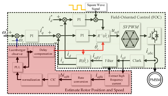
Figure 2.
Block diagram of PMSM control principle based on square-wave voltage injection method.
3. Rotor Position Estimation Method
3.1. High Frequency Response Current Envelope Extraction Method
Feedback current iαβ including fundamental current iαβs and HF response current iαβh. Therefore, it is necessary to extract the HF response current from the feedback current, that is, to realize the demodulation of the HF signal and fundamental signal. The usual method is to use a high pass filter [23], but there will be serious phase delay, and the filtering effect is poor when the injection frequency is close to the fundamental frequency. In addition, dual frequency notch filter [24], second-order generalized integral [25], and other methods are also used to extract HF response current, but the implementation process is more complex.
In order to solve the above problems and simplify the process of high-frequency signal extraction, this paper adopts a HF response current extraction strategy based on the delay module. Since the frequency of the injected HF voltage signal is much higher than the operating frequency, the fundamental current if(k) at time k can be approximately equal to the fundamental current if(k + Th/2) at time k. Since the signs of the injected HF voltage signals at time k and (k + Th/2) are opposite, approximately iαβh(k) = −iαβh(k + Th/2). Therefore, the HF response current is obtained by making a difference between the feedback currents at different sampling times. The equation is as follows:
The above method realizes the approximate HF response current extraction without filter. The method does not produce a large phase delay for the extracted HF response signal, and is not affected by switching frequency and injection frequency. The sampling rate of the HF response current obtained at this time is fs = 1/(Th/2), and the schematic diagram is shown below.
In Figure 3, the transformation multiple of sampling rate R = TPWM/(Th/2), which is used to measure the change of rate. When R < 1, it means that the sampling rate decreases, and when R > 1, it means that the sampling rate increases; TPWM is the switching cycle; Th is the square wave voltage injection period.
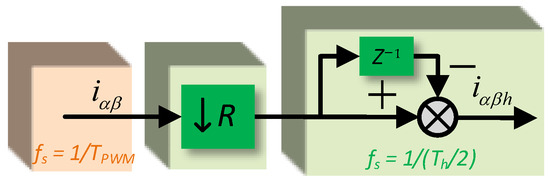
Figure 3.
Schematic diagram of HF-response current extraction.
Next, the envelope of the H- response current, that is, the position quadrature signal, is extracted to estimate the rotor position information. In article [26], QR decomposition is used to extract HF current envelope to reduce the phase lag of the demodulation link, which is relatively complex. Article [27] proposed an envelope extractor. This method only needs the delay model and the symbol of the injected signal, and the HF current envelope can be obtained through subtraction.
However, this method needs to select the sampling point at the midpoint of the period of the injected HF square wave voltage signal, and consider the influence of the delay of the digital control system on the symbol judgment of the injected signal and the influence of the sampling point. At low switching frequency, the method also needs to put a low-pass filter in series at the output to eliminate the disturbance in the extracted quadrature signal, resulting in the increase of control delay.
In order to solve this problem, and to conveniently and effectively extract the position quadrature signal at low switching frequency, this section based on the sampling holding function in the process of sampling rate transformation, and the corresponding sampling rate is fs = 1/Th. The schematic diagram of the sampling rate conversion process is as follows.
In Figure 4, the conversion multiple of sampling rate R = 0.5, Th is the square wave voltage injection period. The method has a simple structure, does not need the symbol information of the injected square wave voltage, and is not affected by the change of switching period. As shown in the Figure 5, when the injected square wave voltage frequency is 500 Hz and the motor is in motion, the position quadrature signal can be extracted by using the sampling rate conversion process.
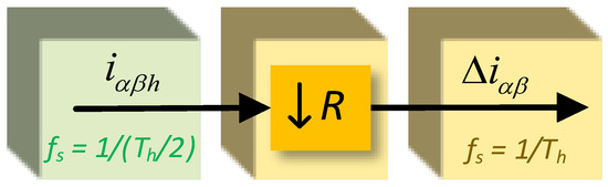
Figure 4.
Schematic diagram of sampling rate conversion process.
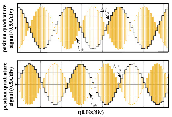
Figure 5.
Schematic diagram of position quadrature signal extraction.
It can be seen from the Figure 5 that although the position quadrature signal can be accurately extracted based on the sampling rate transformation process, due to the low injection frequency, the obtained position quadrature signal changes in steps and has serious distortion, which will lead to obvious steps in the subsequent position estimation and eventually affect the stability of the system. In addition, when the selected square wave voltage injection frequency is reduced, the discretization of the extracted position quadrature signal will be more serious. As shown in Figure 6, it is the estimated rotor position calculated by directly using the position quadrature signal.
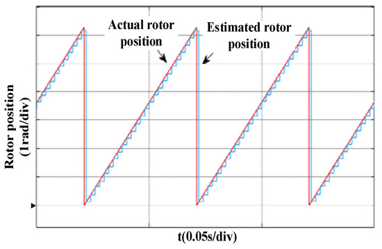
Figure 6.
Estimation of rotor position using position quadrature signal calculation.
3.2. Frequency Matching Method Based on CIC Interpolation Filtering
A filtering method based on quadratic interpolation is proposed in [28], which improves the continuity of the position quadrature signal after quadratic interpolation filtering and effectively eliminates the harmonic components related to the injected signal.
However, this method uses the current sampling value to calculate the fitting value at the last sampling time, so a phase lag will occur, and the lag angle is proportional to the sampling period, so the lower the injection frequency, the larger the phase lag. In addition, the difference between the sampling frequency and the switching frequency of the position quadrature signal is too large, that is, when the switching frequency is more than twice the sampling frequency, the quadratic interpolation can only double the sampling points, which still cannot effectively solve the waveform distortion caused by the sampling holding effect.
In order to solve the above problems, in this section, a frequency-matching method based on CIC interpolation filtering is proposed to interpolate and to match the frequencies of the discrete signals, so that the interpolated quadrature signal has an update frequency consistent with the switching frequency, and the waveform is more continuous and complete. As shown in Figure 7, it is the block diagram of single-order CIC interpolation filter. As can be seen from Figure 7, the filter is composed of a comb filter H1(z) and integrator H2(z) in cascade. It only contains addition and subtraction modules, so it has the advantages of simple structure and low complexity [29]. In addition, the CIC filter is a multi-rate low-pass filter, which is suitable for sampling rate conversion. It can not only realize the extraction from high rate to a low rate, but also realize the interpolation from low rate to high rate.
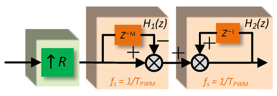
Figure 7.
Block diagram of single order CIC filter.
In position observation, CIC filter can be used to interpolate the position quadrature signal with low sampling rate. The interpolation points increase by the same factor as the sampling rate. Finally, the quadrature signal with sampling rate consistent with the switching frequency can be obtained, the zero-order holder phenomenon caused by low sampling rate can be improved, and the calculation period and current harmonic can be reduced. where M is the order of the filter, that is, the number of beats delayed, which determines the change speed of the output response in the turning region; The transformation multiple of the sampling rate R = M, which determines the number of sampling points inserted by the output signal in the adjacent time interval of the input signal. The system function H(z) of single-order CIC filter can be expressed as:
According to the Noble identity transformation formula, the single-order CIC filter can be equivalently transformed into the following simpler form:
In Figure 8, R = (Th/2)/TPWM, that is, the sampling rate of the position quadrature signal is increased to the switching frequency through interpolation. The multi-order CIC filter is realized by cascading multiple single-order CIC filters to meet the larger amplitude attenuation requirements, but the phase delay will also increase. In this paper, the single-order CIC filter is used. The equivalent structure of the filter can meet the needs of interpolation filtering. As shown in Figure 9, it is a schematic diagram of the interpolation effect after the sampling rate is doubled.
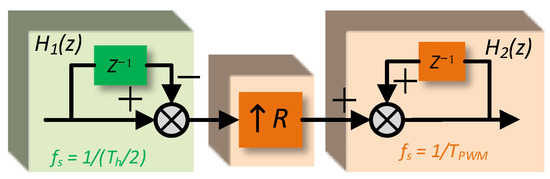
Figure 8.
Equivalent block diagram of a single-order CIC filter.
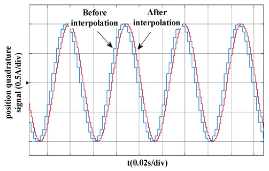
Figure 9.
Schematic diagram of single-order CIC interpolation filtering.
3.3. Observer Design and Stability Analysis
After normalizing the interpolated position quadrature signal, the rotor position error is obtained through the quadrature phase-locked loop, and then the estimated rotor position and mechanical angular velocity are calculated by the Luenberger observer. The principle of the Luenberger observer is detailed in [30,31]. The general control delay varies from 0.75TPWM to 2TPWM depending on the current update-sampling processing method. Considering the position observation, the maximum delay in the zero-low speed range does not exceed 1.5TPWM. Therefore, dynamic angle compensation is performed on the estimated rotor position, and the compensation amount is selected as , is the estimated electrical angle. As shown in Figure 10, it is a block diagram of the position observation principle based on CIC filtering.
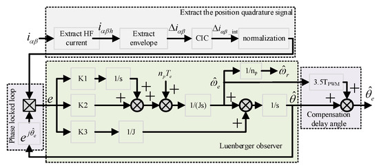
Figure 10.
Block diagram of position observation based on CIC filtering.
The open-loop transfer function of the Luenberger observer is shown in the following equation. Through this observer, the rotor position and speed of the motor can be estimated.
where e is the input to this observer, and represents position estimation error; s represents complex variable; Te and np represent the electromagnetic torque and number of pole pairs, respectively; and are estimated rotor position and estimated electrical angle speed, respectively; K1, K2 and K3 are the variable parameters of the observer, respectively. J represents the moment of inertia.
In order to analyze the stability of the Luenberger observer, and the robustness of parameter changes, the phase locked loop needs to be equivalent to the actual rotor position minus the estimated rotor position in Figure 10, that is, . Since the compensated delay angle does not affect the transfer function of the observer, that is, it does not affect its stability, so it can be ignored. Then the transfer function can be obtained from Figure 10 as follows:
where s represents complex variable; Te and np represent the electromagnetic torque and number of pole pairs of PMSM, respectively; and represent actual rotor position and estimated rotor position, respectively; K1, K2 and K3 are the variable parameters of the observer, respectively. J represents the moment of inertia. The motion equation of the motor is:
Combining Equations (10) and (11), the following can be obtained:
According to the final value theorem, when the load torque is a step signal or a ramp signal, the steady-state error of the observer is 0, so the system has better dynamic performance. When considering observer stability, the closed-loop pole needs to be located on the negative real axis of the s-plane. The general practice is to equal the three poles and make the eigenvalues greater than zero, that is, s1 = s2 = s3 = a (a > 0). The value of a should be adjusted based on the actual situation. Therefore, the theoretical observer parameters are K1 = a3J, K2 = 3a2J, K3 = 3aJ, respectively.
4. Simulation Analysis
In order to verify the effectiveness of the strategy proposed in this paper, this section will be verified by simulation. The parameters of the PMSM used in the simulation are shown in Table 1.

Table 1.
Permanent magnet synchronous motor parameters.
The position quadrature signal extracted from the HF corresponding current is tested by simulation. The simulation condition is set as a no-load condition, the reference speed is 300 rpm, the frequency of injected square wave voltage is 500 Hz, and the switching frequency is 1 kHz.
Figure 11 shows the position quadrature signal without CIC interpolation filtering and its FFT analysis diagram, and Figure 12 shows the position quadrature signal with CIC interpolation filtering and its FFT analysis diagram. By comparing Figure 11a and Figure 12a, it can be seen that the position quadrature signal without CIC interpolation filtering has obvious discontinuity, and its harmonic content is richer, which has an adverse impact on the subsequent position estimation and increases the estimated position error. By comparing Figure 11b and Figure 12b, it can be seen that the waveform of position quadrature signal filtered by CIC interpolation is smoother, the harmonic content is significantly reduced, and the interference of HF signal can be well filtered. In addition, after interpolation, the sampling rate of the waveform is increased to the switching frequency, which can improve the calculation frequency of the estimated position, and improve the accuracy of position estimation.
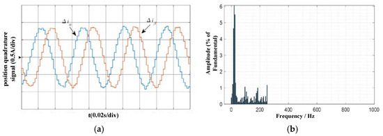
Figure 11.
Position quadrature signal without CIC interpolation filter and its FFT analysis. (a) Position quadrature signal; (b) FFT analysis.
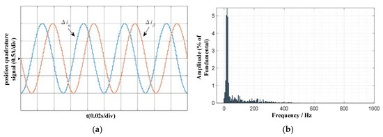
Figure 12.
Position quadrature signal filtered by CIC interpolation and its FFT analysis. (a) Position quadrature signal; (b) FFT analysis.
Then, the steady-state performance of the proposed control strategy is tested by simulation. Figure 13 and Figure 14 are waveforms of the estimated position signal reference 100 rpm and 300 rpm under no-load conditions, respectively. It can be seen from the figure that the maximum position estimation error is no more than 0.1 rad, the observer can better estimate the rotor position at different reference speeds. Therefore, the proposed strategy can be well applied to sensorless control in the zero low speed range at 1 kHz low switching frequency.
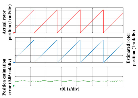
Figure 13.
Simulation waveform at a reference speed of 100 rpm under no-load.
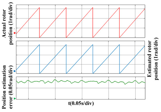
Figure 14.
Simulation waveform at a reference speed of 300 rpm under no-load.
In addition, the dynamic characteristics under the proposed control strategy are tested by simulation. Figure 15 and Figure 16 show the estimated position waveforms and the corresponding phase current waveforms at a reference 100 rpm and 300 rpm in the case of a sudden load of 3 N.m. It can be seen from the figure that in the whole loading process, the maximum position estimation error does not exceed 0.26 rad., Therefore, the control system has strong anti-disturbance under different reference speeds.
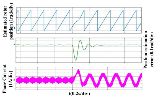
Figure 15.
Sudden load simulation waveform at a reference speed of 100 rpm.
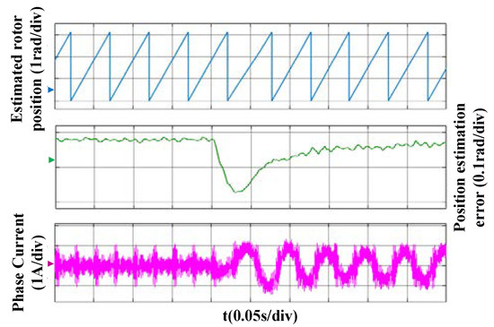
Figure 16.
Sudden load simulation waveform at a reference speed of 300 rpm.
Finally, the starting and dynamic characteristics of the sensorless control system is tested by simulation. Figure 17 shows the simulation waveform of the no-load start process. As can be seen from Figure 17, the motor starts from a standstill, and then sets the reference speeds of 150 rpm, 300 rpm, and 100 rpm, and makes a smooth transition between different reference speeds. During the simulation process, the maximum rotor position error does not exceed 0.12 rad, the maximum speed error does not exceed 40 rpm, and the speed overshoot does not exceed 21 rpm.
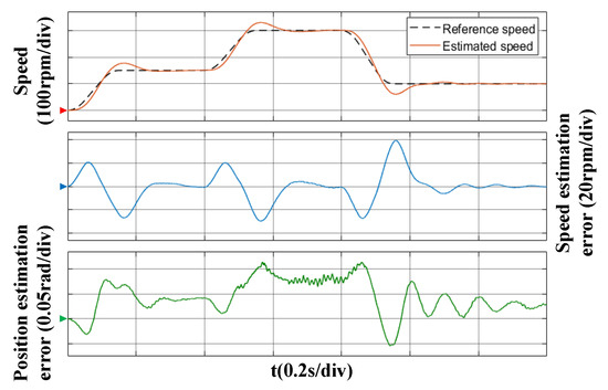
Figure 17.
Simulation waveform of no-load starting process.
Figure 18 shows the simulation waveform of the motor running with load of 3 N.m. As can be seen from Figure 18, the motor starts from a standstill, and then sets the reference speeds of 150 rpm, 300 rpm, and 100 rpm, and makes a smooth transition between different reference speeds. During the simulation process, since the electromagnetic torque of the motor increases from 0, it will reverse due to the influence of the load torque, but it can quickly track the reference speed, so the system has a certain robustness, and the maximum rotor position error does not exceed 0.34 rad, the maximum speed error does not exceed 63 rpm, and the speed overshoot does not exceed 30 rpm. Therefore, the sensorless control system still has better dynamic performance under load.
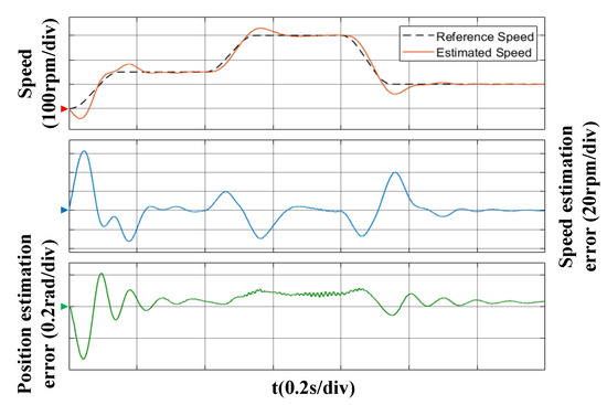
Figure 18.
Simulation waveform of load starting process.
5. Conclusions
In this paper, the HF square wave voltage injection method is used to realize the sensorless control in the range of zero and low speed at 1 kHz switching frequency. At the low switching frequency, due to the limited injection frequency, the update frequency of the position quadrature signal extracted by the square wave voltage injection method is lower than the PWM update frequency, which leads to the problem that the estimated position ripple is too large.
A method based on CIC interpolation filtering is proposed in this paper. By this method, when the injected square wave voltage frequency is 500 Hz, the signal-processing strategy reduces the harmonic content of the position quadrature signal while increasing the sampling rate of the signal. Then, the delay angle is compensated by using the PWM update frequency and the estimated rotational speed. Simulation results show that the position estimation error of the system does not exceed 0.34 rad, and the speed estimation error does not exceed 63 rpm when the speed is adjusted in the low-speed area of not more than 300 rpm. Thus, the proposed sensorless control strategy can improve the control performance of the system.
Author Contributions
Literature search, Graph production, Study design, Data collection, Data analysis, Data processing, Manuscript writing, Z.X.; Manuscript review, Data analysis, L.L.; Manuscript Review, Data processing, X.W. (Xiaolu Wang); Literature Search, Graph Production, X.W. (Xin Wang). All authors have read and agreed to the published version of the manuscript.
Funding
This research received no external funding.
Institutional Review Board Statement
Not applicable.
Informed Consent Statement
Not applicable.
Data Availability Statement
Exclude this statement.
Conflicts of Interest
The authors declare no conflict of interest.
References
- Öztürk, N.; Çelik, E. An Educational Tool for the Genetic Algorithm-Based Fuzzy Logic Controller of a Permanent Magnet Synchronous Motor Drive. Int. J. Electr. Eng. Educ. 2014, 51, 218–231. [Google Scholar] [CrossRef]
- Celik, E.; Dalcali, A.; Ozturk, N.; Canbaz, R. An adaptive PI controller schema based on fuzzy logic controller for speed control of permanent magnet synchronous motors. In Proceedings of the 4th International Conference on Power Engineering, Energy and Electrical Drives, Istanbul, Turkey, 13–17 May 2013; pp. 715–720. [Google Scholar] [CrossRef]
- Filho, C.J.V.; Xiao, D.; Vieira, R.P.; Emadi, A. Observers for High-Speed Sensorless PMSM Drives: Design Methods, Tuning Challenges and Future Trends. IEEE Access 2021, 9, 1. [Google Scholar] [CrossRef]
- Wang, G.; Valla, M.I.; Solsona, J.A. Solsona. Position Sensorless Permanent Magnet Synchronous Machine Drives—A Review. IEEE Trans. Ind. Electron. 2019, 67, 1. [Google Scholar] [CrossRef]
- Ribeiro, L.; Degner, M.; Briz, F.; Lorenz, R. Comparison of carrier signal voltage and current injection for the estimation of flux angle or rotor position. In Proceedings of the Industry Applications Conference, St. Louis, MO, USA, 12–15 October 1998. Thirty-Third IAS Annual Meeting. [Google Scholar] [CrossRef]
- Bui, M.X.; Guan, D.; Xiao, D.; Rahman, M.F. A Modified Sensorless Control Scheme for Interior Permanent Magnet Synchronous Motor Over Zero to Rated Speed Range Using Current Derivative Measurements. IEEE Trans. Ind. Electron. 2018, 66, 1. [Google Scholar] [CrossRef]
- Haoyuan, L.; Xing, Z.; Shuying, Y.A. Detecting Algorithm for Initial Position of Interior Permanent Magnet Synchronous Motor Based on Rotating High Frequency Injection. Trans. China Electrotech. Soc. 2018, 33, 1723–1731. [Google Scholar] [CrossRef]
- Xiaoyuan, L.; Gang, L.; Kun, M. Initial Position Detection of Permanent Magnet Motor Based on Virtual Pulsating High-Frequency Injection Method. Trans. China Electrotech. Soc. 2017, 32, 34–41. [Google Scholar] [CrossRef]
- Wang, G.; Xiao, D.; Zhao, N.; Zhang, X.; Wang, W.; Xu, D. Low-Frequency Pulse Voltage Injection Scheme Based Sensorless Control of IPMSM Drives for Audible Noise Reduction. IEEE Trans. Ind. Electron. 2017, 64, 1. [Google Scholar] [CrossRef]
- Lu, Q.; Wang, Y.; Mo, L.; Zhang, T. Pulsating High Frequency Voltage Injection Strategy for Sensorless Permanent Magnet Synchronous Motor Drives. IEEE Trans. Appl. Supercond. 2021, 31, 1. [Google Scholar] [CrossRef]
- Wang, S.; Cao, D.; Yang, Y.; Wang, F. Sensorless Control of PMSM with Positive and Negative High Frequency Pulse Voltage Signal Injection. IEEE Trans. Ind. Electron. 2020, 35, 164–171. [Google Scholar] [CrossRef]
- Dong, K. Research on Key Contrl Techniques and Performance Optimization of Traction Drive System for EMUs; Beijing Jiaotong University: Beijing, China, 2015. [Google Scholar] [CrossRef]
- Zhang, Y.; Yin, Z.; Liu, J.; Zhang, R.; Sun, X. IPMSM Sensorless Control Using High-Frequency Voltage Injection Method with Random Switching Frequency for Audible Noise Improvement. IEEE Trans. Ind. Electron. 2019, 67, 1. [Google Scholar] [CrossRef]
- Reigosa, D.D.; Garcia, P.; Briz, F.; Raca, D.; Lorenz, R.D. Modeling and Adaptive Decoupling of High-Frequency Resistance and Temperature Effects in Carrier-Based Sensorless Control of PM Synchronous Machines. IEEE Trans. Ind. Appl. 2010, 46, 139–149. [Google Scholar] [CrossRef]
- Tang, Q.; Shen, A.; Luo, X.; Xu, J. IPMSM Sensorless Control by Injecting Bi-directional Rotating HF Carrier Signals. IEEE Trans. Power Electron. 2018, 33, 1. [Google Scholar] [CrossRef]
- Gou, L.; Wang, C.; You, X.; Zhou, M.; Dong, S. IPMSM Sensorless Control for Zero-and Low-Speed Regions under Low Switching Frequency Condition Based on Fundamental Model. IEEE Trans. Transp. Electrif. 2021, 8, 1182–1193. [Google Scholar] [CrossRef]
- Eskola, M.; Tuusa, H. Sensorless control of salient pole PMSM using a low-frequency signal injection. In Proceedings of the European Conference on Power Electronics & Applications IEEE, Dresden, Germany, 11–14 September 2005. [Google Scholar] [CrossRef]
- Zhang, Y. Sensorless Control of IPMSM with Low Audible Noise and Full Speed Range Operation; Xi’an University of Technology: Xi’an, China, 2021. [Google Scholar] [CrossRef]
- Chu, J.; Zhu, Y.; Zhang, K. Random high frequency signal injection demodulation strategy in double angle coordinate system. Electr. Mach. Control. 2021, 25, 21–30. [Google Scholar] [CrossRef]
- Xie, G.; Lu, K.; Dwivedi, S.K.; Rosholm, J.R.; Blaabjerg, F. Minimum-Voltage Vector Injection Method for Sensorless Control of PMSM for Low-Speed Operations. IEEE Trans. Power Electron. 2015, 31, 1785–1794. [Google Scholar] [CrossRef]
- Zhang, H.; Liu, W.; Chen, Z.; Luo, G.; Liu, J.; Zhao, D. Asymmetric Space Vector Modulation for PMSM Sensorless Drives Based on Square-Wave Voltage-Injection Method. IEEE Trans. Ind. Appl. 2017, 54, 1425–1436. [Google Scholar] [CrossRef]
- Lee, Y.; Kwon, Y.; Sul, S. Comparison of rotor position estimation performance in fundamental-model-based sensorless control of PMSM. In Proceedings of the 2015 IEEE Energy Conversion Congress and Exposition (ECCE), Montreal, QC, Canada, 20–24 September 2015; pp. 5624–5633. [Google Scholar] [CrossRef]
- Luo, X.; Tang, Q.; Shen, A.; Zhang, Q. PMSM Sensorless Control by Injecting HF Pulsating Carrier Signal into Estimated Fixed-Frequency Rotating Reference Frame. IEEE Trans. Ind. Electron. 2016, 63, 2294–2303. [Google Scholar] [CrossRef]
- Liu, J.; Fu, K.; Mai, Z.; Xiao, F.; Zhang, W. Sensorless Control Strategy of Improved HF Pulsating Voltage Injection Based on Dual Frequency Notch Filter. Proc. CSEE 2021, 41, 749–758. [Google Scholar] [CrossRef]
- Huang, X.-H.; Han, C.-C. Harmonic Suppression for Low Speed Sensorless Control of SPMSM Based on High Voltage Frequency Pulsating Signal Injection. In Proceedings of the 2019 IEEE 3rd Information Technology, Networking, Electronic and Automation Control Conference (ITNEC), Chengdu, China, 15–17 March 2019; pp. 686–690. [Google Scholar] [CrossRef]
- Toso, F.; Berto, M.; Alberti, L.; Marcuzzi, F. Efficient QR Updating Factorization for Sensorless Synchronous Motor Drive Based on High Frequency Voltage Injection. IEEE Trans. Ind. Electron. 2019, 67, 1. [Google Scholar] [CrossRef]
- Zhang, G.; Wang, G.; Xu, D.G. Filterless Square-Wave Injection Based Initial Position Detection for Permanent Magnet Synchronous Machines. Trans. China Electrotech. Soc. 2017, 32, 7. [Google Scholar] [CrossRef]
- Zhang, G.; Xiang, R.; Wang, G.; Zhang, H.; Xu, D. Pulse Signal Injection in Stationary Reference Frame for Sensorless PMSM Drives. Proc. CSEE 2021, 41. [Google Scholar] [CrossRef]
- Singh, R.K.; Katiyar, A. Design and implementation of CIC based decimation filter for improved frequency response. In Proceedings of the 2009 International Conference on Emerging Trends in Electronic and Photonic Devices & Systems IEEE, Varanasi, India, 22–24 December 2009; pp. 236–240. [Google Scholar] [CrossRef]
- Vadstrup, P.; Lorenz, R.D. Robust Estimator Design for Signal Injection-Based IPM Synchronous Machine Drives. In Proceedings of the Industry Applications Conference, Seattle, WA, USA, 3–7 October 2004; Volume 2, pp. 957–963. [Google Scholar]
- Kim, D.; Kwon, Y.-C.; Sul, S.-K.; Kim, J.-H.; Yu, R.-S. Suppression of Injection Voltage Disturbance for High-Frequency Square-Wave Injection Sensorless Drive with Regulation of Induced High-Frequency Current Ripple. IEEE Trans. Ind. Appl. 2016, 52, 302–312. [Google Scholar] [CrossRef]
Publisher’s Note: MDPI stays neutral with regard to jurisdictional claims in published maps and institutional affiliations. |
© 2022 by the authors. Licensee MDPI, Basel, Switzerland. This article is an open access article distributed under the terms and conditions of the Creative Commons Attribution (CC BY) license (https://creativecommons.org/licenses/by/4.0/).