1. Introduction
In the event of a natural disaster, rescue teams race against time. The chance of survival of the surviving injured is significantly reduced if not rescued in 72 h [
1]. In disaster areas, the work of rescuers is challenging because entering such areas can be dangerous for the lives of the injured. Therefore, rescue teams have a limited time window for search and rescue activities. In such cases, the work of rescue teams can be assisted by using robot technology [
2]. The use of heavy machinery in collapsed structures poses a significant risk for the injured trying to survive due to the inadequacy of the space between pieces of rubble. The spot-location of those under the debris is tried to be determined by the combined and separate use of search dogs, cameras, and listening devices. Many robot systems that use wireless communication technology have been used for search and rescue activities in recent years [
3,
4,
5]. These robots should transmit vital data to the relevant people accurately and quickly to speed up search and rescue activities. However, robots used for search and rescue are costly, and there is no government incentive or funding for the construction and production of such robots [
6]. Therefore, this is not an option for most underdeveloped countries. The time constraint and difficulty of post-earthquake search and rescue operations underline the need for a less costly and fast-operating casualty location detection system. Robots developed using Arduino boards are not very old [
7,
8]. There are many documents and books on the usage of these boards. In addition, the sensors compatible with Arduino boards, such as infrared, distance, humidity, and temperature sensors, are inexpensive and accessible because of their widespread use [
9]. In this study, a team consisting of multiple search and rescue robots was designed; a multi-robot coordination algorithm based on the Bat Algorithm (BA), one of the nature-inspired optimization algorithms that have expanded in recent years, was tested on these robots.
Studies on BA have shown that this algorithm gives better results than the others, such as particle swarm optimization, firefly algorithm, and harmonic search [
10]. It is expected that the study will contribute significantly to the literature with the improvements made for pathfinding and robot coordination. There are studies on using robot technology for search and rescue efforts in disaster situations. These studies generally performed e-puck or Arduino-based improvements [
11]. Various sensing and wireless technologies are used in disaster areas, including remote and image control [
12]. Rescue teams can remotely control search and rescue robot systems using these technologies when natural disasters occur instead of entering the devastated area [
12]. However, there are very few studies in our country on determining the location of the people under collapsed buildings after an earthquake using robots. Furthermore, BA’s prevalence and usage areas increase day by day. Its popularity has increased even more because many studies have proved its efficiency and effectiveness. Thus, a bat-inspired algorithm was desired to be developed for multi-robot coordination.
This study has two objectives. The first is to develop a system that can detect the location of people in rubbles after an earthquake. The second is to develop a new multi-robot coordination system based on a bat-inspired algorithm. In this section, these two objectives and sub-objectives are detailed. One of the study’s objectives is to determine the people’s positions in rubbles with a low error margin after the earthquake. Some coercions limit manageability in signal transmission. However, the signal enhancer and signal filtering techniques used in the study helped overcome these issues. Another objective is to achieve the desired objective with a robot system that is less costly than existing systems. Thus, an Arduino-based robot platform, which is lower than an e-puck in cost, is preferred in the study.
Multi-robot coordination is a method used in situations where more than one autonomous robot is used for operations such as navigation, mapping, and patroling [
12]. There are two forms of coordination: centralized and decentralized [
13]. The studies should be evaluated according to these features. Developing a bat-inspired algorithm for multi-robot coordination is one of the main objectives. The desired result is achieving a method superior to its counterparts in terms of time, complexity, and effectiveness. The study aimed to accelerate search and rescue activities in natural disasters. The multi-robot coordination algorithm developed in this study will set an example for future studies in this field. Sheng et al., offered a multi-robot coordination model for limited communication situations [
14]. Perception and mapping were the key aspects of the model. The direction of the robots was determined using an information acquisition function. In addition, the study contained a special algorithm for map synchronization. The method was tested with six robots in a simulation setting and successfully used the available data. However, this study did not compare the method used for coordination with other methods. The outcomes included only the communication range and the test results [
15]. Talebpour et al. [
15] examined multi-robot coordination in dynamic environments containing humans. Multi-robot coordination was also used to map unknown environments [
16]. The algorithms for searching and finding the optimum solution, such as A* and greedy, were used. They failed to reduce the number of idle robots in coordination entirely. Huang et al. [
17] developed an algorithm that scans an area and measures the robot’s exploration performance for an unknown environment.
Kandhasamy et al., developed a route planning method for decentralized multi-robot control and supported it with a special messaging system [
18]. The robot positioning and mapping system developed by Tchuiev et al., produced promising results in simulation environments regarding time [
19]. However, the performance should be remeasured in environments with factors affecting communication between robots. In addition, it would be more effective to compare the system with similar methods instead of evaluating it only in itself. One of the collaboratively developed methods for solving complex problems was found in the study of Queralta et al. [
20].
There are many studies in the literature about rescue robots. One of them presented an improved network system for the rescue robot [
21]. In addition, although it produced successful results in a simulation environment, it was not a sound system for multiple robots. Rescue zones are not entirely flat; therefore, it is necessary to develop robot systems that overcome the obstacles. Bai et al., designed a new transformable wheeled-legged robot mechanism for search and rescue missions in complex terrains. There is a need for such systems in this field.
Moreover, collaboratively using more than one robot is desirable in search and rescue activities [
22]. Joseph et al., developed an Arduino-based rescue robot to detect people stranded in land or water areas affected by natural disasters, serving the additional purpose of carrying emergency food and medical aid to people [
23]. The performance of such robots is limited when used for both search and rescue purposes. Human intervention is needed in cases where robot capability is limited. Sound pickups are also required on rescue robots. Mae et al., developed rescue robots for search and rescue operations in times of large-scale disaster. The robot they developed is used to search for survivors in disaster areas by capturing their voices with its microphone array. Performing in a simulated disaster area, they confirmed that a survivor could sense the direction of their position using a noise reduction technique [
24]. One of the improvements made on Arduino boards belongs to Kiran et al. [
25]. They have developed a search robot equipped with various sensors that can be controlled via wireless using Arduino Board (Mega and Uno). The system was cost-effective, but a user should manage it entirely, which is its downside. Today, there is a need for autonomous robots that can act independently and collect vital information from a single point. Buzduga et al., developed a system that detects the number of people in earthquake rubbles using Arduino Uno [
26]. The stability of the developed system was insufficient due to the distance constraints of the sensors used. Akkhar et al., offered a robot system developed for search and rescue purposes [
27]. The system developed with Arduino Mega could be controlled remotely with BlueTooth and includes an arm with good mobility. The system was not self-directing and did not work for distances longer than 10 m. An algorithm that plans robot paths was developed in 2018 [
28]. It investigated the possibility of using a new evolutionary-based technique based on Teaching-Learning Based Optimization (TLBO) to solve a mobile robot’s navigation problem in a wild environment. The results of the algorithm were validated by comparing them with the outcomes of other intelligent algorithms such as particle swarm optimization (PSO), weed optimization (IWO), and biogeography-based optimization (BBO). The heuristic Q-learning method was presented in 2015 [
29]. This method was richly compared with different methods. However, this study has tested the robot in a known setting. The method should be renewed for a completely unknown setting and multi-robots. The ABACO algorithm [
30], developed by Ajeil et al., based on the ant colony algorithm, was tested in many experimental settings and compared with many methods. However, multi-robot coordination was not considered in this study.
Regarding theoretical richness, one of the significant studies tried to establish multi-robot coordination with hierarchical clustering [
31]. This study is different from the others in terms of the originality of the method and simulation. In Muthukumaran et al. [
32], a new meta-heuristic optimization technique called Dragonfly Algorithm (DA) is used to navigate an autonomous mobile robot in an unknown complex setting full of static obstacles. Various static settings were modeled in the method, and the algorithm was tested both in simulation and experimentally. They showed that the robot reached the target with the proposed algorithm without hitting any obstacles and created a smooth optimal trajectory. Apart from Arduino, the E-puck robot system has also been used in robot navigation studies [
33]. One of its essential advantages is that the sensors that will be needed are integrated. The cost of this robot, which occupies a small space, is higher than Arduino. Vijay Kumar and Dinesh Kumar presented a comprehensive review of the Firefly Algorithm (FA) [
34]. They examined various variants of FA, such as binary, multi-objective, and hybrid, with other meta-heuristics. They provided applications and performance improvement metrics. Luke et al., simulated the results using binary classifiers to determine performance criteria in classifying unbalanced datasets and developed a systematic analysis based on the binary confusion matrix [
35].
Gürgöze et al. [
36] researched and comparatively analyzed algorithms used in robotic systems. Ahmet Sami Dog˘ru and Tolga Eren examined the nature algorithms [
37]. They concluded that the error rate of BA is less than other algorithms and gives more accurate results. Lee et al., performed a sinogram-based map assembly study [
38].
Ramm et al., explained applied tomography’s theoretical, computational, and practical aspects with Radon transform [
39]. Huang presented a brief review of different optimization strategies used in the simultaneous localization and mapping (SLAM) problem [
40]. Jain et al., provided an overview of research progress on Particle Swarm Optimization (PSO) between 1995–2017. They discussed the progress, improvements, modifications, and applications of PSO [
41]. Mirjalili explained the general structure of a genetic algorithm and applied it to several studies to observe its performance [
42]. Yang et al., reviewed BA and its derivatives and examined some of the sampled real-world optimization applications [
43]. Moshayedi et al., discussed various shapes and applications of all existing service robots. They summarized the key points of the research progress, such as robot dynamics, types of robots, and different dynamic models of different types of service robots. The study can be accepted as a starting point for all researchers on this subject [
44]. Moshayedi et al., investigated the relationship between the methods considered on the AGV robot instead of introducing the PID controller and seeing the effect of each parameter on the whole system. This review shows various PID tuning methods used according to system requirements through a humoral neural network called Lyapunov Direct Method, traditional Ziegler Nichols, and Fuzzy supervisory human immune system [
45]. Moshayedi et al., reviewed the contributions and new applications of deep learning. The study aimed to summarize significant points so that academicians can analyze applications and algorithms. Also, the advantages of using the deep learning method and its hierarchical and non-linear operation were introduced and compared with traditional algorithms in typical applications [
46]. Moshayedi et al., aimed to establish a much more efficient and cost-effective system with minimal effort through a secure SCADA for monitoring. They showed that having a territorial idea helps the system achieve the purpose of safe sensor monitoring without any outside interference. As a result, they showed a successful design and implementation of the zone idea and excellent use of the Raspberry Pi as a small and reliable mainframe [
47]. Moshayedi et al., introduced and tested a simple algorithm for Persian vocabulary and implemented a robot structure based on Arduino. The critical point of the study was the use of sound signals in the Persian language, which has less than twenty years of history. The success rate exceeded 70% in the trials [
48]. Fozuni et al., analyzed the stability and convergence of particle dynamics in the standard BA version, addressed the limitations, and proposed new update relations [
49]. In addition, the dynamics of the algorithm were investigated, and sufficient stability conditions were obtained using Lyapunov stability analysis. Belge et al., used the hybrid HHO-GWO algorithm in their work, distinguished by its avoidance of local minimums and speed convergence, to successfully obtain a feasible and efficient path [
50]. The experimental results showed that the proposed algorithm creates a fast and safe optimal path without getting stuck with local minima. The quadcopter followed the path created with minimum energy and time consumption.
This study compared machine learning algorithms for multiple robots that work concurrently. Thanks to data sharing between collaborative robots through sensors, they would not use the paths that other robots scanned, allowing them to reach the desired output sooner. Earthquake zones were chosen for testing machine learning algorithms. Regarding the literature, no configuration used BA in robot systems that work in integration with each other. From this point of view, it is expected that this study will take its place as an original study in the literature.
In this study, a robot system was designed within the scope of multi-robot coordination. First, a robot with more than one sensor was designed, and then algorithms deciding the robot’s movement were developed. Studies on BA were reviewed. BA provided better results than the other algorithms covered in the study, which was a reason for preferring to use BA. Virtual and concrete settings have been built, and the robots determined the location and direction by working collaboratively. The performances of BA and some other machine learning algorithms were compared, and the results were interpreted.
2. Materials and Methods
The system for implementing multi-robot coordination is designed as follows: First, the robot was designed. Then, the Bat-Inspired Multi-Robot Coordination Algorithm (BIMRCA) was developed. The robot moved following algorithm rules. BIMRCA coordinated the robots moving in the determined area. Other machine learning algorithms were also tested in addition to BIMRCA. Machine learning algorithms and features that can be used in multi-robot coordination systems are listed below (Gürgüze et al., 2019).
- 1
Simultaneous Localization And Mapping (SLAM):
SLAM Algorithm moves the robot that maps the setting and uses that map to calculate its position.
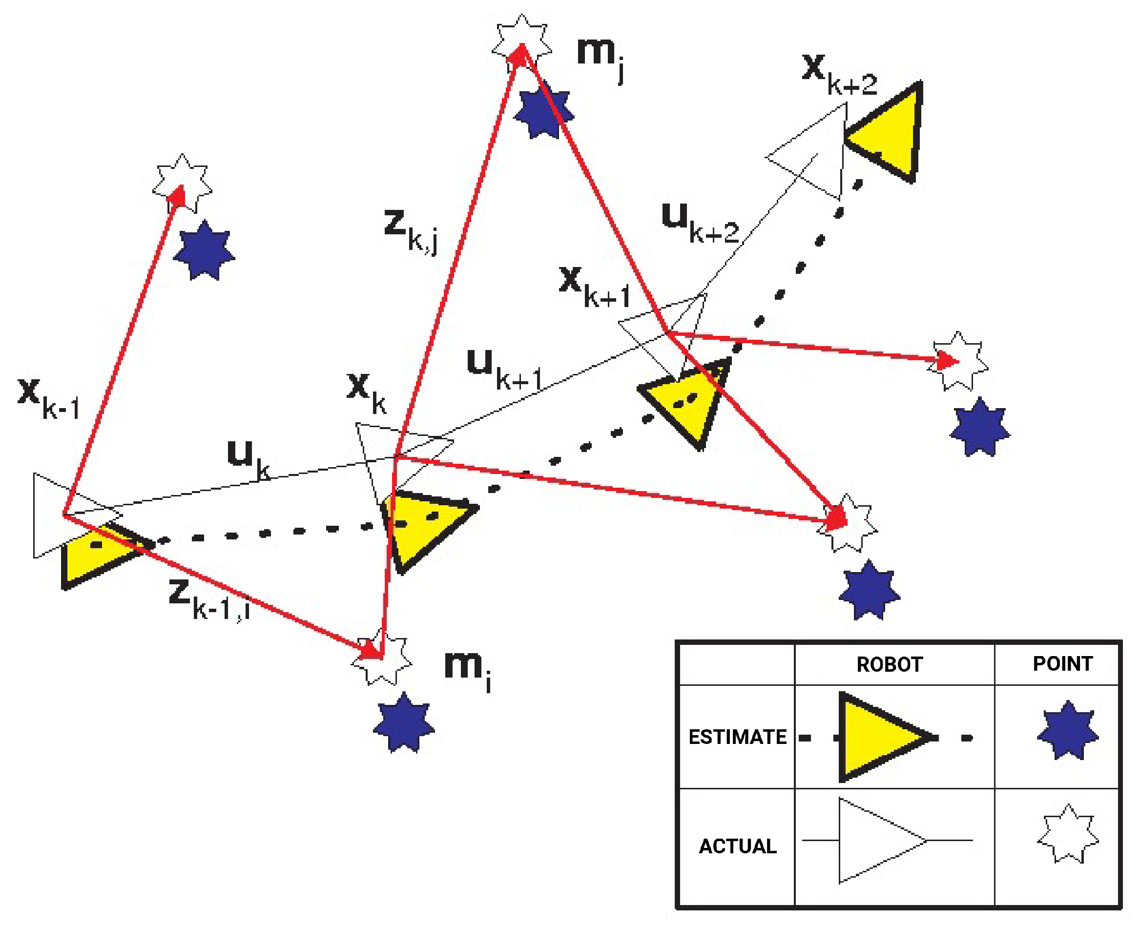
Figure 1 below shows how the SLAM algorithm works.
According to the figure above, all sensor data is read from the used robot in time “
k”.
X represent the robot’s position information, “
U” control input information, m the entire set of signals, and
Z marks observations. The formula generally used for the algorithm is below:
X is the robot’s position information, U control input information, m is the entire cluster of signals, and Z is the entire mark observation cluster.
- 2
Random Particle Swarm Optimization (RPSO):
- 3
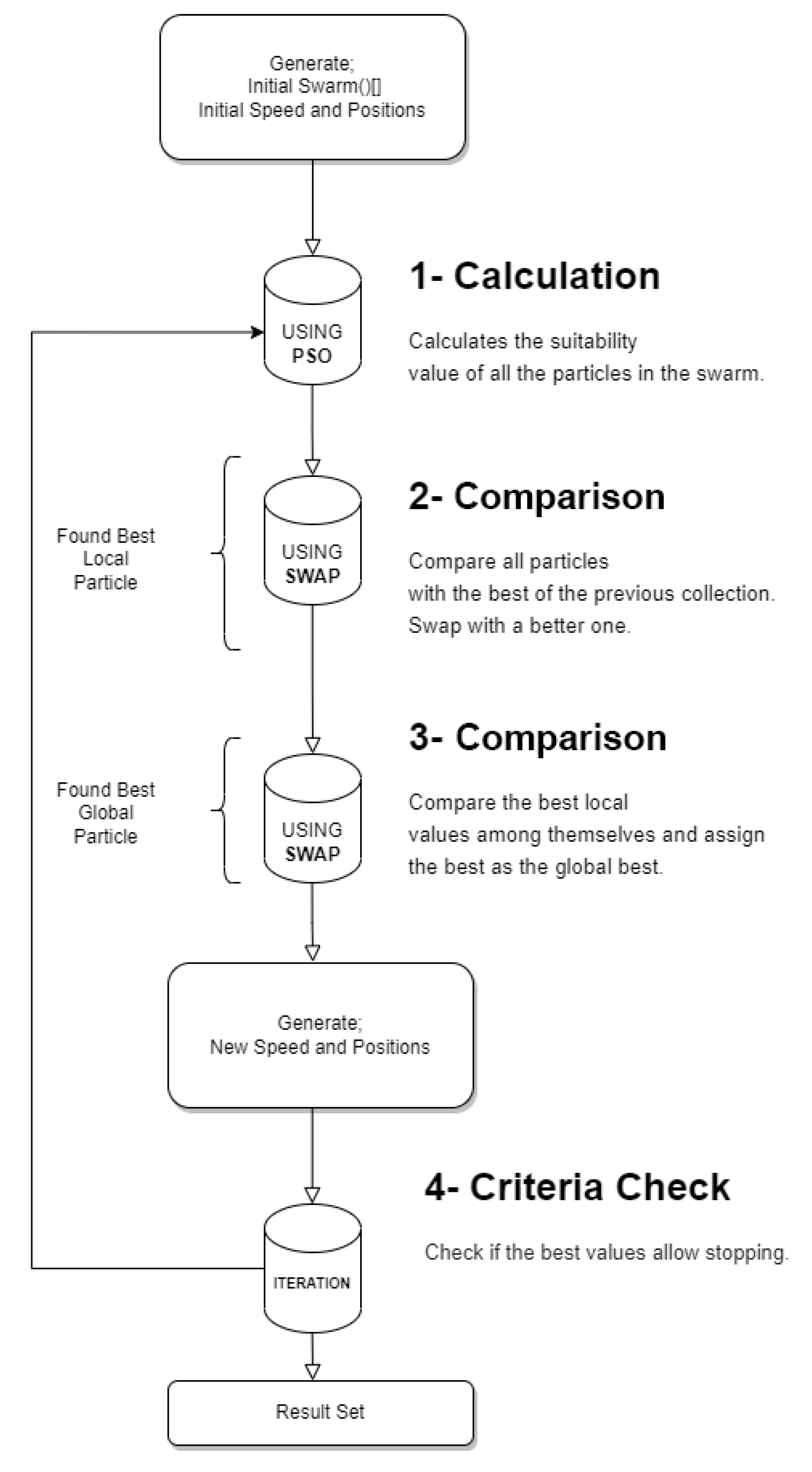
Particle Swarm Optimization (PSO):
Proper path planning:
- -
The collision avoidance rate was higher in short periods
Usage Areas:
- -
It is used in many fields such as function optimizations, training artificial neural network models, fuzzy logic systems and image processing.
The formula of the algorithm is expressed as follows:
The velocity (
V) of particle “I” at time
k + 1 is given above.
W refers to the inertia factor,
is the particle’s coefficient, and
is the swarm-related coefficient.
is the best point of the particle, and
is the best point of the swarm. These values are multiplied by a random number and summed up to determine the next move. The new position
is obtained with this movement [
41]. The flowchart of the algorithm is shown in the
Figure 2.
- 4
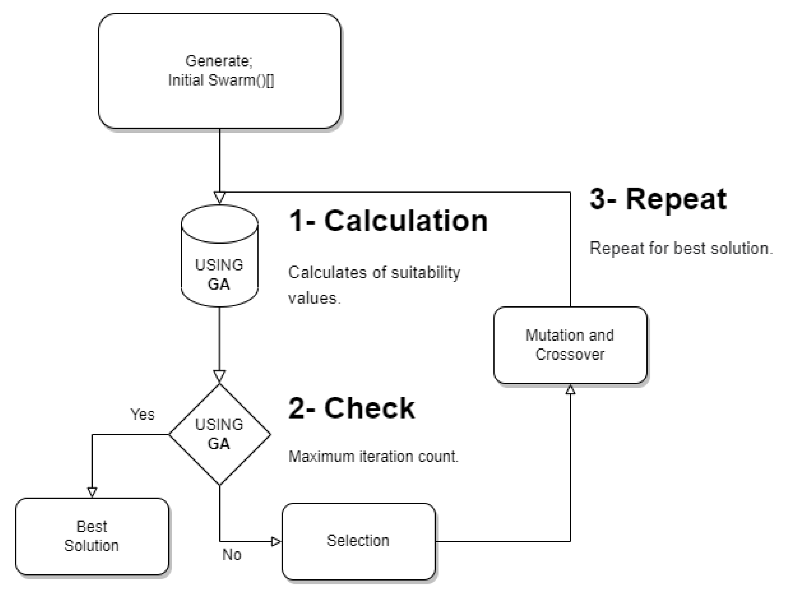
Genetic Algorithm (GA):
Starting point:
- -
An improved GA approach was proposed to find suitable paths in multiple moving robots.
The general implementation formula of the algorithm can be expressed with the following code (pseudocode):
START
Create population
Calculate Compliance
START CYCLE
(Selection)
(Crossover)
(Mutation)
(Compute fitness)
STOP CYCLE Is the termination criterion met?
STOP
GA is a family of evolution-inspired computational models. These algorithms encode a possible solution to a particular problem on a simple chromosome-like data structure and apply recombination operators to these structures to preserve critical information. GA is often seen as a function optimizer, even though applied to many problems.
Process steps of GA are illustrated in
Figure 3:
- 5
Bat Algorithm (BA):
Starting point:
- -
Bats use echolocation to compute their distance from their prey and distinguish between prey/food and objects/obstacles.
- -
Bats were observed to find their targets.
Hybrid approach:
- -
Performance efficiency was determined as 69.4% for GA, 74% for PSO, and 79.8% for GAPSO hybrid.
- -
A hybrid approach including GA and PSO was offered to increase the performance of robots in industrial lines.
Usage Areas:
- -
It is successfully applied to solve problems in almost all optimization areas and appears to be very efficient.
Stability Analysis:
- -
Stability analysis was performed using the Lyapunov stability concept. Lyapunov stability analysis is based on the idea that if the total energy in the system continuously decreases, the system will asymptotically reach the zero energy state associated with the equilibrium point. The results reveal that the Lyapunov energy function decreases with time in the stability range of the algorithm’s parameters, and the particles’ trajectory shows the asymptotic stability of the particle dynamics [
49].
Bats gave appropriate values that affect the direction and subsequent movements of the entire population, randomly distributed in the area. Bats determine their next position depending on a specific frequency (
fi) and the solution value (
x) of the best individual in the population for the speed (
vi) they generate. BA is formulated with the following equations [
43]:
Accordingly,
fi represents the bat’s frequency;
fmin and
fmax the minimum and maximum frequencies, respectively;
xit represents a randomly distributed value in the range [0, 1];
x* represents the best individual value in the population at time
t;
vit, represents
t: instance and the speed of the
i. individual [
43]. According to the above formulas, the algorithm’s complexity in its most optimized form is O(n). The operational steps of the algorithm can be illustrated as follows:
2.1. Robot Design
One of the most critical points considered in designing a robot is that the robot should move easily in uneven areas. Nowadays, many regions of the world are affected by natural disasters. Disasters include exceptional and unstoppable natural events such as earthquakes, forest fires, floods, or events triggered by human errors like building collapses. This situation reveals the importance of search and rescue robot systems in the emergency field [
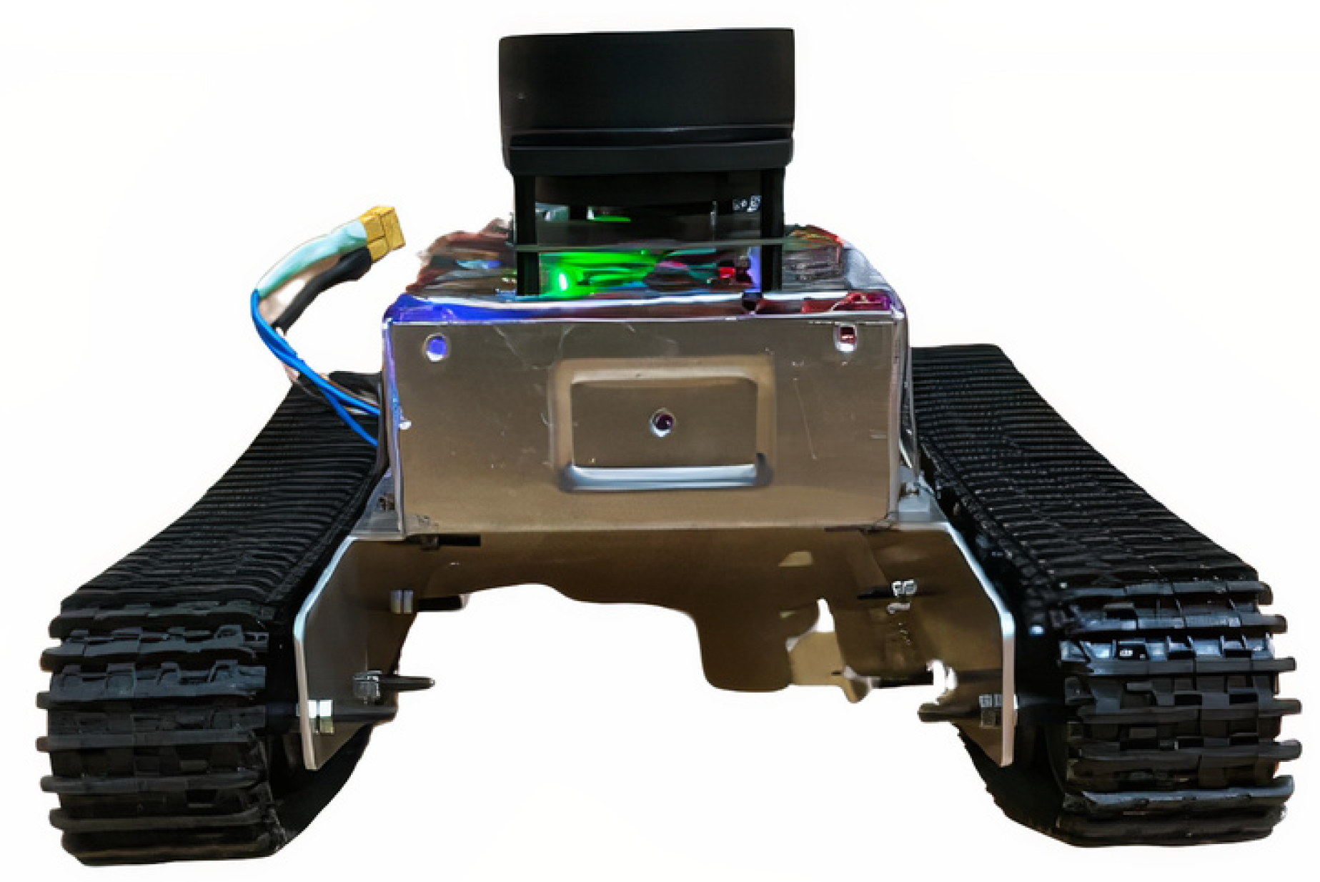
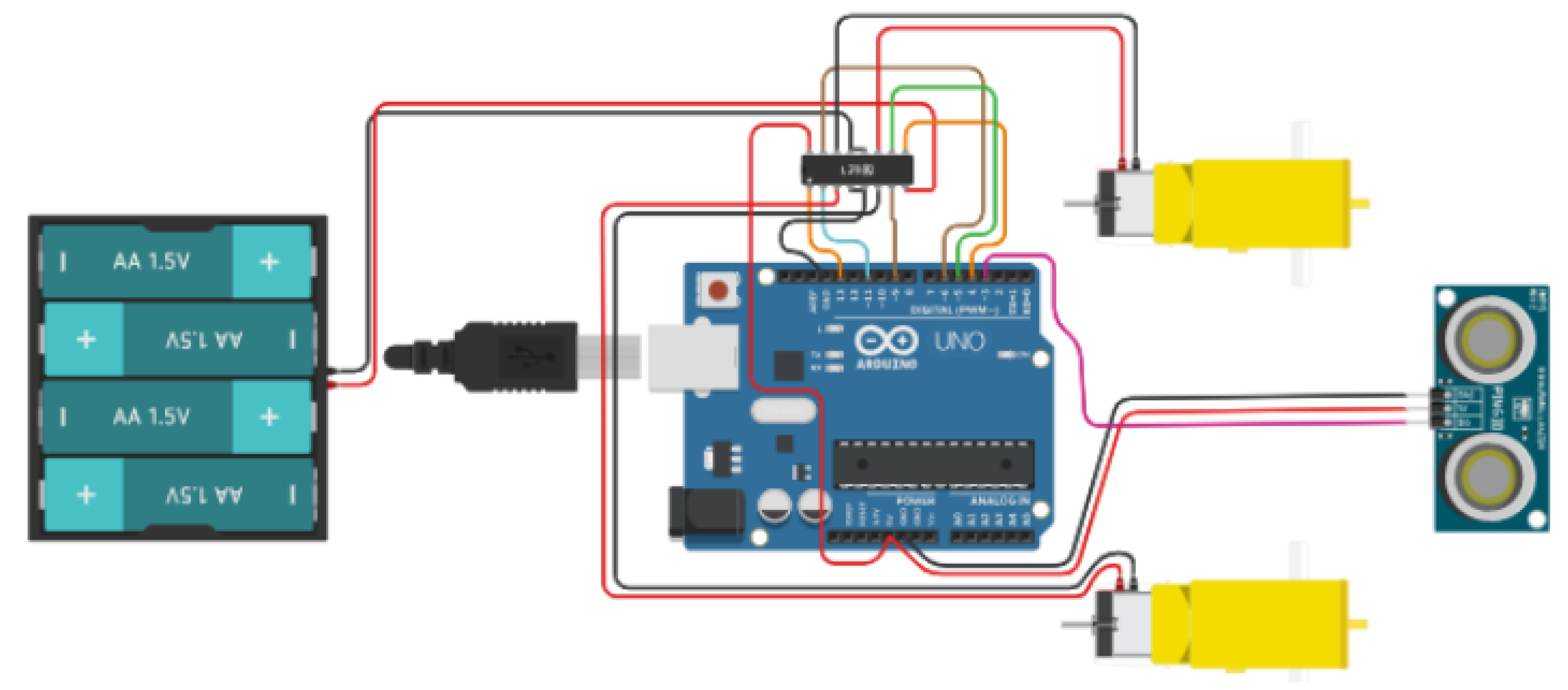
11]. The developed robot has sensors such as infrared, distance, temperature, RP-lidar, an encoder motor, and transceivers that support broadband communication for inter-robot communication.
Figure 4 shows the picture of the equipped robot that has been designed and operated.
The UGVs (Unmanned Ground Vehicles) used in real life are shown above. The robots were named NE-1001, SE-1002, and E1003, where NE—northeast, SE—southeast, and E—east. Mybot was used in the mapping of the simulated setting. Mybot is a robot with an RP-lidar on it. It is capable of listening to the developed software.
The hardware is made of all-steel material with proper holes to keep it cool. Thus, it is protected against falling, overturning, and overheating. The algorithms process the data collected by the sensors, and the robot’s behavior is decided after the design takes its final shape. If a robot has scanned a path during the search process, other robots do not repeat this task. Thus, the search is carried out faster. The information received from the sensors was first recorded in a database and then sent to the algorithm. A new task was defined for the robot that completes a task. After completing these steps, the software makes a decision based on the parameters collected by the robot searching for life under the debris and recognizing the human body. These parameters are temperature, the distance between the robot and the object, size, and motion.
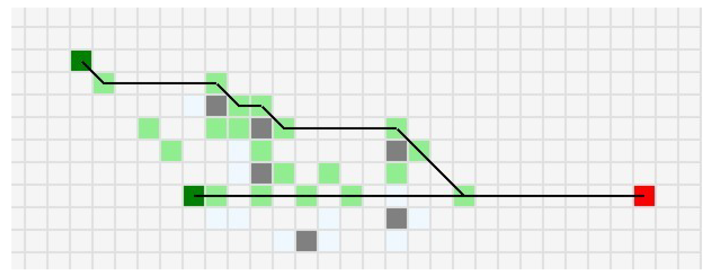
Figure 5 shows the robot reaching the target point using the distance and temperature data.
The algorithm ensures a new path is drawn by covering all the existing lines and checked boxes on the grid, as shown in the figure above. A path is set for the second robot, shown with a second line on the grid. The important thing here is to increase the starting points to enhance the communication between the robots and increase the endpoints. Increasing the number of robots, which also means increasing starting points, causes a competitive approach. On the other hand, the robot’s movement was reviewed if direction changes occurred regarding the obstacle’s size while the robot progressed towards the target. The times that the robot got out of the obstacles and moved in different directions regarding the obstacle size were recorded in three different settings.
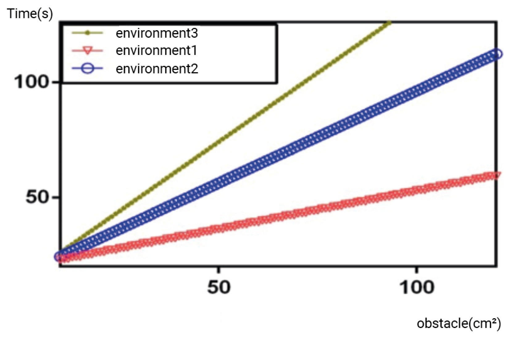
The times of determining a new direction for getting out of the obstacles in three different settings are given in
Figure 6. The barrier density of the medium is calculated as in Equation (1). Accordingly, Environment 1 is an environment with an obstacle density of 25%. Environment 2’s obstacle density is 50%, and Environment 3 has an obstacle density of 75%. Obstacle crossing time increases quadratically in Environment 3. The main reason is randomly generated motor speeds in the method while determining the new direction. The random motor speed generation function is repeated when they get the same values as the old direction, which increases the time to cross the obstacle. There is no quadratic increase for Environment 1 and Environment 2 because there are not enough obstacles to increase the obstacle clearance time in these two environments.
The algorithm developed in the robot’s course of motion to any targeted destination is shared in Algorithm 1, where speed1 and speed2 are the variables used to change the robot’s direction. Speed1 and speed2, which allow the robot to move straight, are set to 80. The robot constantly controls the distance between itself and the obstacle while moving on a straight course. If the variables that contain data from the ultrasonic sensors fall below 40 cm for distance and distance2, then the motor speed values directly become 0, and the robot is stopped. Subsequently, random motor speeds are assigned, and the robot is expected to cross the obstacle. The processes described so far work in the same way for the ultrasonic distance sensors on the back of the robot. These sensors are named distance3 and distance4 and are defined in the algorithm.
| Algorithm 1 Robot distance algorithm |
Procedure Require: Require: Ensure: if or then else if then else end if if then else end if if or then else if then else end if if then else end if End Procedure |
If the algorithm is run step by step for the sample data, the initial distance data for the two sensors in the front are distance = 60 and distance2 = 60. When the algorithm was run step by step, it worked as follows:
In the first iteration the following values are assigned; distance and distance2 60 and randNumber = −35 randNumber2 = 20. M1Speed and M2Speed values will change according to these values.
In the second iteration the following values are measured after the robot’s movement; distance = 45, distance2 = 70 and randNumber = −10 randNumber2 = 40. M1Speed and M2Speed values will change according to these values.
In the third iteration, the following values are measured; distance = 35, distance2 = 55. In this case, the first condition of the algorithm is met, and the motor speed becomes 0.
In the fourth iteration, motor speeds are assigned as 50, and distance values are read as 65 and 75.
In the fifth iteration, randNumbers are set as follows: randNumber = −5 randNumber2 = 55. Accordingly, M1Speed and M2Speed become 60 and 130.
In the sixth iteration, distance = 5, distance2 =15. In this case, the motor speed reset.
These processes continue until the robot scans the entire area.
2.2. BIMRCA
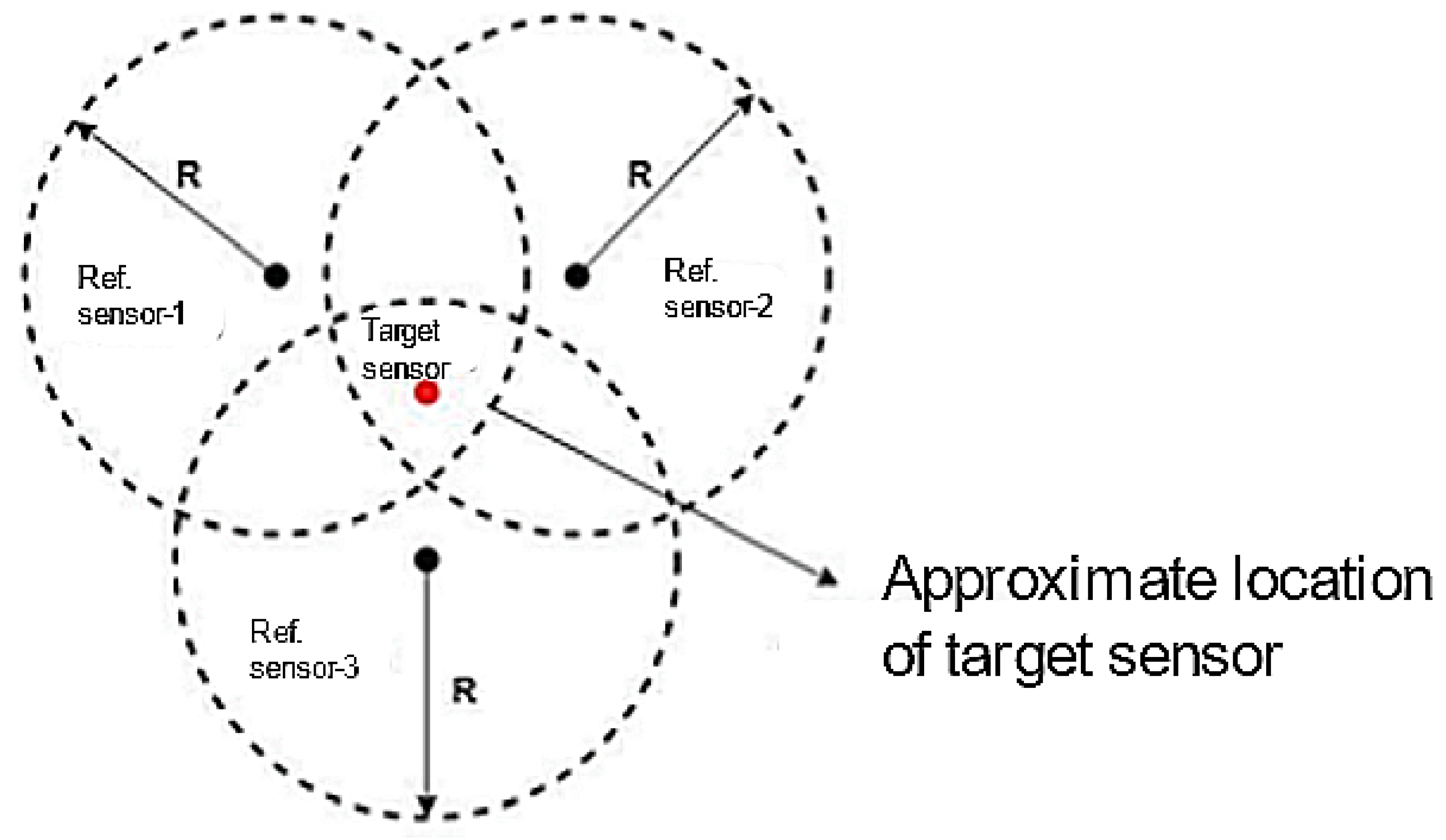
BIMRCA was developed in this part of the study. Path planning methods have been developed for 3D and 2D environments using BA, which has never been used for multi-robot coordination before. Considering the promising results of BA studies, the researchers decided to develop BIMRCA. The projected algorithm uses more than one robot in the system concerning their location, effectively determining survivors’ location. The data obtained from the infrared, distance and temperature sensors are used and processed in the algorithm to decide the robot’s behavior. As a result, the search is carried out faster. The setting is mapped while the robot is in motion. This modeling can be examined in a grid structure, as seen in
Table 1. The representation in
Table 1 is also called the proximity grid. Suppose that R steps will be taken from the distance grid information in
Table 1. Then;
is calculated by the number of partitions for each row. Similarly, the number of partitions in each column can be represented by;
Here y represents the column. Each grid has its own coordinate and is represented by an Id.
The coordinates around the robot also change as a result of its movement. For example, the new proximity grid formed after the robot reaches a new position by moving one step on the x-axis and one step on the y-axis is shown in
Figure 7.
Bearing all these in mind, a unique algorithm inspired by bats has been developed to coordinate multiple robots.
The implementation of BIMRCA is shown in Algorithm 2. The details and steps can be explained as follows. RobotSensorDegerMatrix is a matrix containing the information about the temperature of the object the robot encounters, the ambient temperature, and the distance of the robot from the closest object at its right, left, bottom, and top, respectively. Wavelength refers to the distance between successive crests of a wave. Wavelength is obtained by dividing robot speed by frequency in this algorithm. Frequency refers to the robot’s motion to the target. The obstacle the robot encounters or the distance to the target is the loudness. Pulse is a positive value that increases as the robot approaches the target. First, the variables are set, assigned to the variables in the algorithm and kept in the matrix. Then, the wavelength is set as (randNumber + randNumber2)/2. The robot’s upper-left distance is set as the frequency, and the sum of the robot’s bottom-left, upper-right, and bottom-right values is set as the default loudness. If the ambient temperature is between 27 and 340 °C, the pulse value increases by 0.1, and the loudness value decreases by 1 due to the favorable conditions.
| Algorithm 2 Bat-Inspired Multi-Robot Coordination Algorithm |
Input: Procedure: while do if and then end if if then end if if or then end if if or then end if if or then end if if or then end if return end while End Procedure |
The pulse value is positive because the robot is close to finding the object it is looking for. The pulse takes a value between 0–1 here. In cases where the ambient temperature is 340 °C or higher, the engine stops immediately, the loudness is set as 0, and the pulse value as 1. It can be interpreted as the robot finding the object it is looking for, stopping in this position, and increasing the pulse value to the highest value, 1. Finally, thanks to the sensors on the robot, the upper-left, bottom-left, upper-right, and bottom-right values collected by the robot are compared with each other, and the pulse and loudness values are adjusted. The robot can sense whether it is approaching the target or not with this setting.
The table below shows the variables’ changes during the algorithm’s testing.
According to
Table 2, two random numbers were generated in each iteration and assigned to the randNumber and randNumber2 variables. The average of these variables was set as the wavelength. The robot approached the target step by step and stopped its operation when the pulse value became 1 in the 7th iteration when it reached the target.
3. Findings
Virtual settings were created to test the algorithm and compare it with the others. Various environmental conditions and obstacles (roughness, heat source) were tested with different scenarios and forced the algorithm within the simulation settings. This study will interpret the findings obtained in two virtual and one concrete simulation setting.
Simulation 1: A virtual setting was created. Three virtual robots were used, and the training ground was a flat surface. Wall-like structures were added to the setting to limit the robots’ motion range. The movement of the robots was monitored. Robots have started their movements using sensors to scan the entire area as quickly as possible. Each robot transferred the information of the scanned areas to each other every two seconds so that they did not repeat the search on scanned areas. As seen in
Figure 8, the position of Robot 1 will give the optimum result if it moves straight and turns to the right. At this point, Robot 1, which was advancing straight and could not make any progress due to the obstacle (wall) in front of it, randomly determined a new direction. The algorithm said to turn to the upper left, and the robot has decided to move in that direction. However, the controls conducted during the robot’s movement detected an obstacle (wall) at the top left, and the robot had to be redirected. As a result of the determined redirection, the robot decided to move to the right and continued its move.
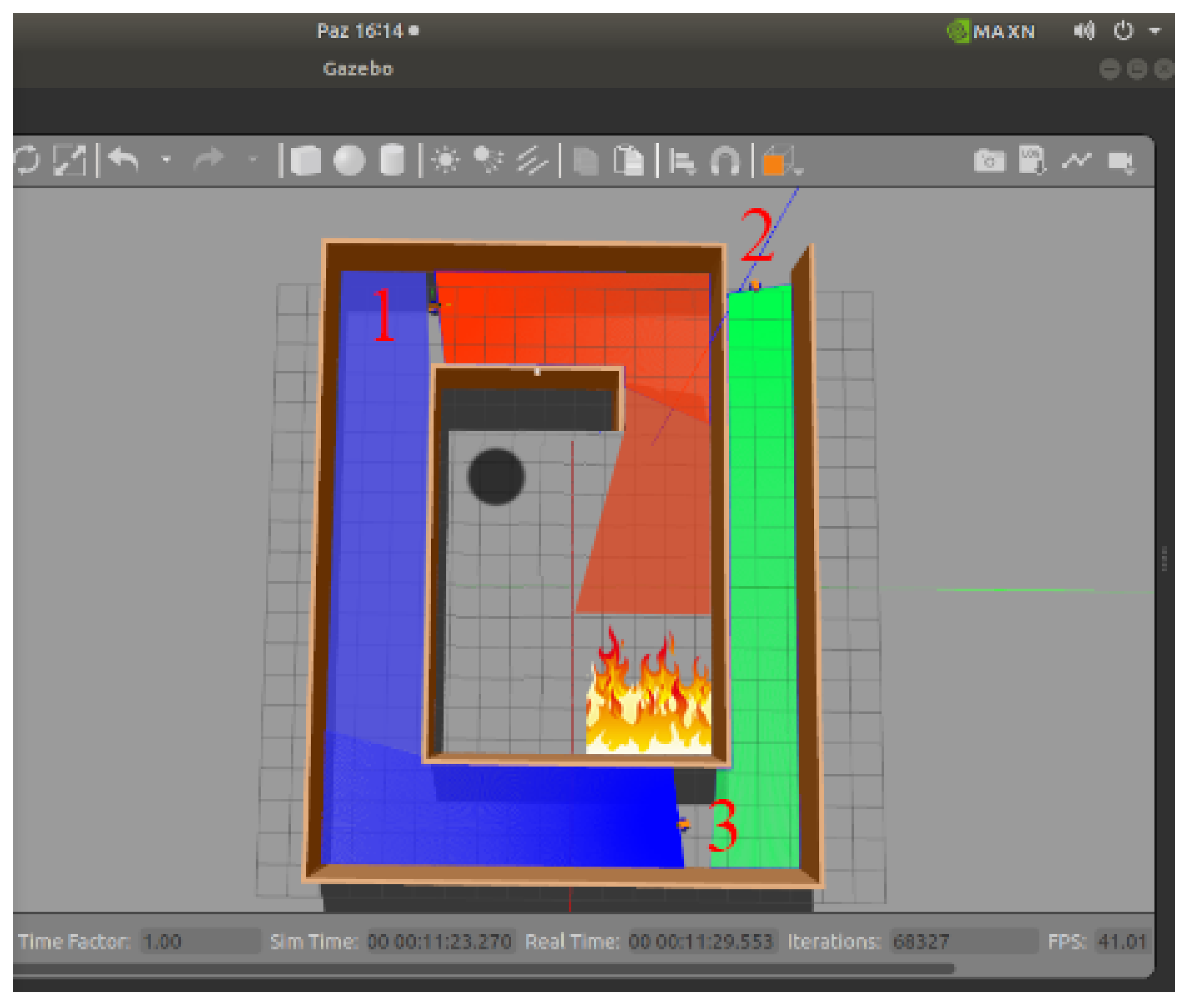
Simulation 2: After getting the optimum result from the first simulation, a new simulation setting was created, adding a heat source and a target to be recovered to the setting. Regarding the setting shown in
Figure 8, robot1 moved to the middle zone. The obstacle detection function started to work slowly as the data from the temperature sensor increased above 34 °C as it approached the heat source it faced. Then the robot reduced its movement and determined a new direction. In this way, the entire area that could be explored by staying away from the heat source was scanned. When it approached the target shown as a black dot, it informed the others that there was an entity to be rescued here using temperature sensors. Robot2 and robot3 used the other areas and came near the overlapping areas. Regarding the information received from robot1, they decided that they had reached the target and ended their movements. The scanned area is shown in
Figure 9. The area scanned by Robot 1 is shown orange, the area scanned by Robot2 with green, and the area scanned by Robot 3 with blue by the simulation.
The numbers 1, 2 and 3 appearing in
Figure 8 and
Figure 9 represent the robots in different positions. In addition, they collect map information obtained by simultaneous scanning of robots at locations. Then, this collected data is combined to form a single map.
Tests were conducted with different algorithms in similar simulation settings to validate the collaborative work of the robots in finding targets. Error rates of the tests from collected accuracy, sharpness, sensitivity, and F criterion data are shown in the results section. The robots and the algorithm were tested in a concrete setting after completing the observations in the simulated setting. The setting used to obtain the data has been designed to liken actual structures to a certain extent by using brick, concrete and wooden materials. The robot navigation area shown in
Figure 10 consisted of 8 units. Seven of these units were designed to be large enough for the robot to enter, and one unit had a curved obstacle surface. The units were numbered as shown in the figure. Apart from these, there were also obstacles interspersed among them. The robot can enter the sheltered area in two moves using two front distance sensors for the nook entrance assembly. If there is no departure zone behind the sheltered area, scanning continues in this area.
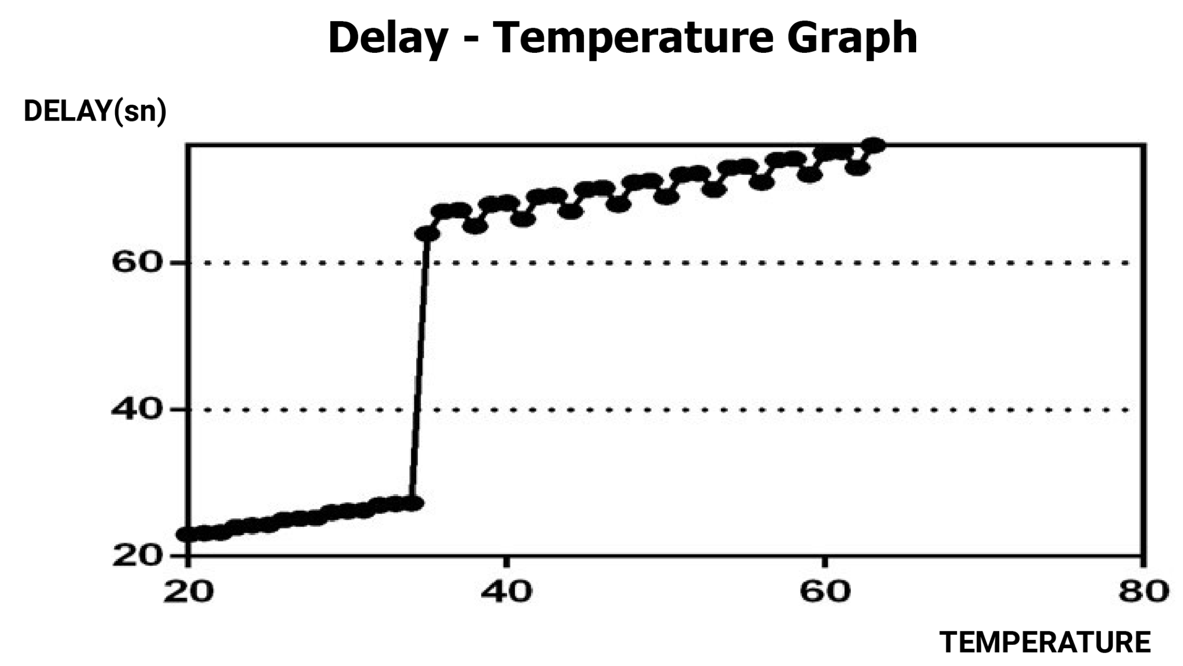
Since all hardware is made of steel, it must be kept cold. Therefore, the temperature rise above a certain level poses a problem for the healthy operation of the algorithm.
Figure 11 shows the delay in the obstacle detection function after detecting the heat. Delays of up to 34 °C are acceptable, depending on the function. The proposed algorithm reorientated the robot since the engine stops above this temperature.
The numbers from 1 to 8 indicated in
Figure 10 consist of the real-life adaptation of the houses in the simulation environment.
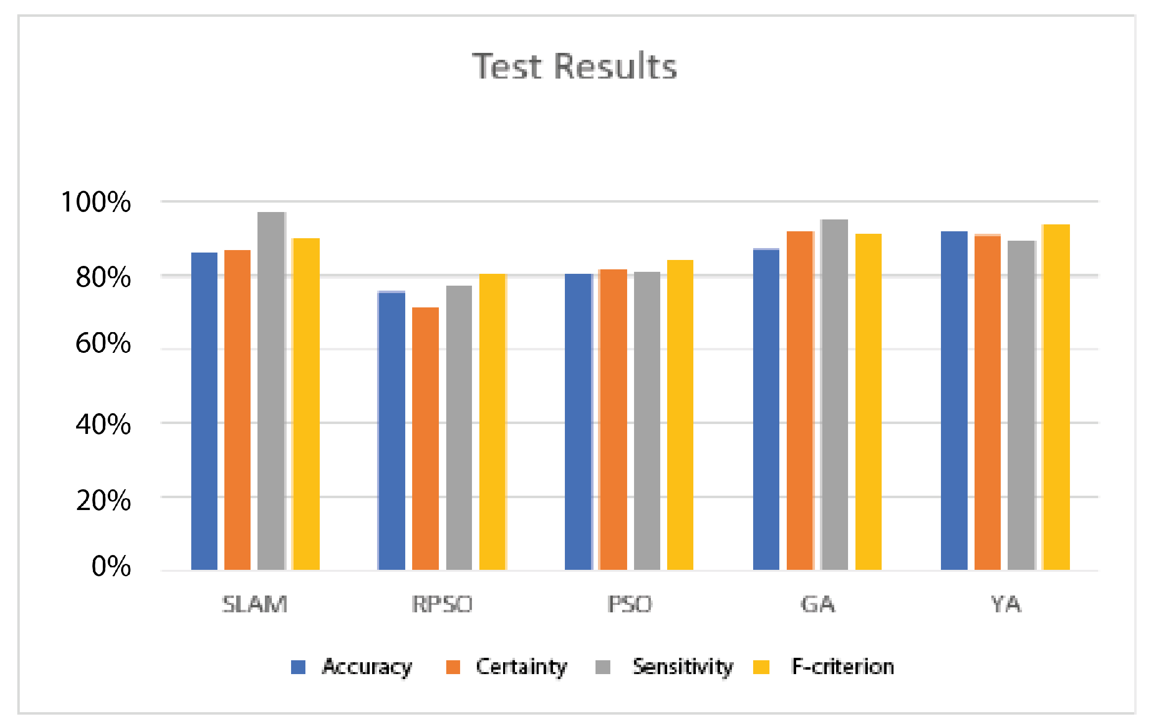
4. Results
In this study, BIMRCA was suggested as an algorithm for casualty detection in earthquake collapses. An intuitive coordination system was developed using the robot’s sensor values in the bat-inspired algorithm. The designed robots determine new directions by moving randomly according to the position of obstacles such as roughness, wall, and temperature. Tests were made for these scenarios in simulated settings and the created training platform. The robots were observed to determine a random direction according to the obstacles in their path. They also share information with other robots via wireless communication when they detect an injured using temperature sensors. Two algorithms have been developed for both the obstacle and the intuitive movement in this context. The main challenge during the experiment was the ultrasonic distance sensors’ coverage area because the coverage of the sensors was kept narrow to prevent possible collisions with walls or other obstacles. This situation makes it challenging to map the environment. A new motion is determined in cases when the data from the sensors indicate a distance below 40 cm. Another challenge was the inability to create an educational model for direction determination with the old data. Therefore, a new direction was determined t times depending on the obstacle density for each encountered obstacle. For the algorithm to give the best performance, the frequency should be less than 35, the loudness greater than 30, the temperature should be 270 °C or above, and the wavelength should be greater than 40. Because, regarding the algorithm results, progress was observed in iterations with these values. In future studies, the direction can be determined faster by introducing the obstacle in the environment through the education process.
In addition, the image control can be made with a camera and a mobile device when the robot stops, and the algorithm working principle can be altered with user intervention. Depending on the snapshots taken from the camera on the robot, the variables can be changed so that the algorithm can enter a different state and work differently. In addition to these, maps with different characteristics can be analyzed, the optimum number of robots required in disaster areas can be determined, and the resources can be allocated and used more efficiently. Bat-Algorithm (BA), Simultaneous Localization and Mapping (SLAM), Random Particle Swarm Optimization (RPSO), Particle Swarm Optimization (PSO), and Genetic Algorithm (GA) were tested in simulated and concrete settings. The data were created by taking the average of 50 simulations, one concrete setting, and the written scenarios of simulated tests. Test results are shown in
Figure 12.
The Accuracy, Sharpness, Sensitivity and F-Measure data in
Table 3 are taken from the complexity matrix, a table often used to describe the performance of a classification model.
Equations of the concepts used in performance evaluation are below.
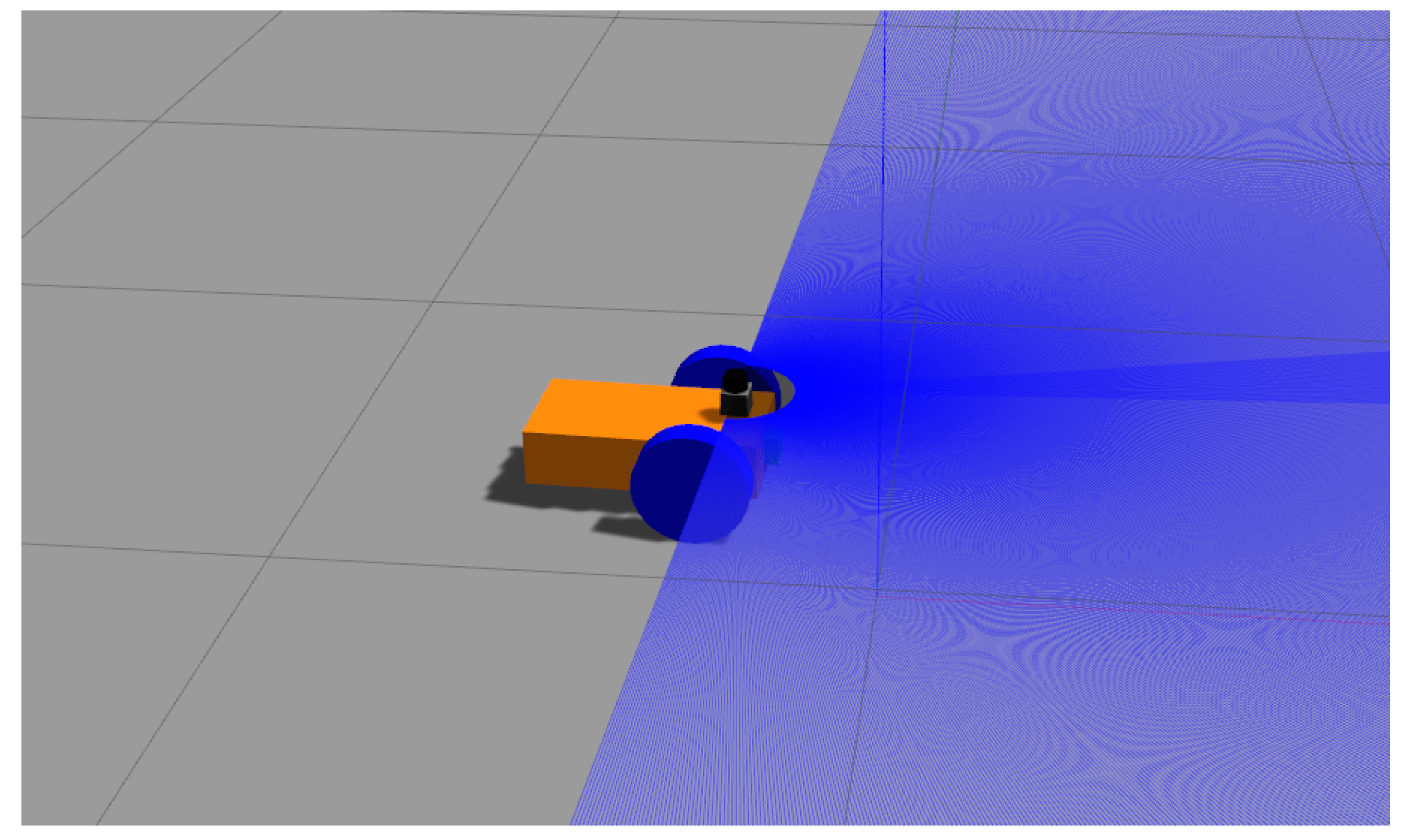
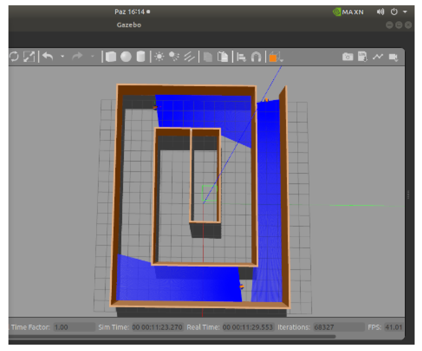
As a result of the simulation, the most successful algorithm for positioning the robots was BA. The robots have been observed to transfer relative location information without any problems using BA. The simulations of the robots’ location information are given in
Figure 13 and
Figure 14. The blue areas show the areas within the robot’s line of sight.
The simulation showed that the SLAM algorithm was the most successful in 2D mapping. The communication between the robots is continuous in this method. Uninterrupted communication can also be achieved by using a large number of robots.
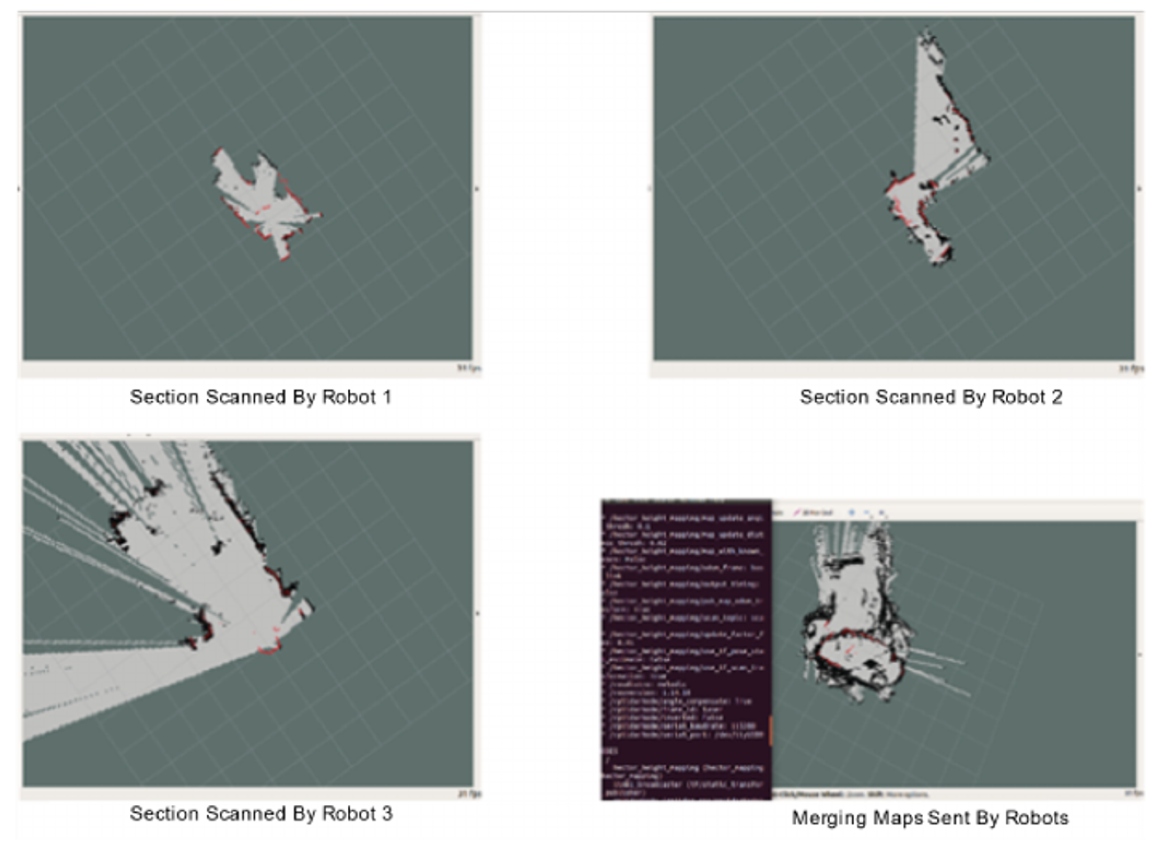
BA tests compared the performance and processing load requirements of SLAM algorithms. The effects of measuring noise and motion noise on BA have been demonstrated, showing that the increase in system performance shortens the time spent in BA. Regarding the experiments conducted in the concrete setting, robots created their zones and mapped them without entering each other’s area, shared maps, and merged them on a common map. Robots transfer the information of the scanned area to each other through various sensors and continue their movements with the information of these scanned areas. Therefore, a robot knows whether an area has been scanned or not and proceeds accordingly. The maps created by the robots are shown in
Figure 15. The red and black areas in the images show the areas detected by the sensors as obstacles.
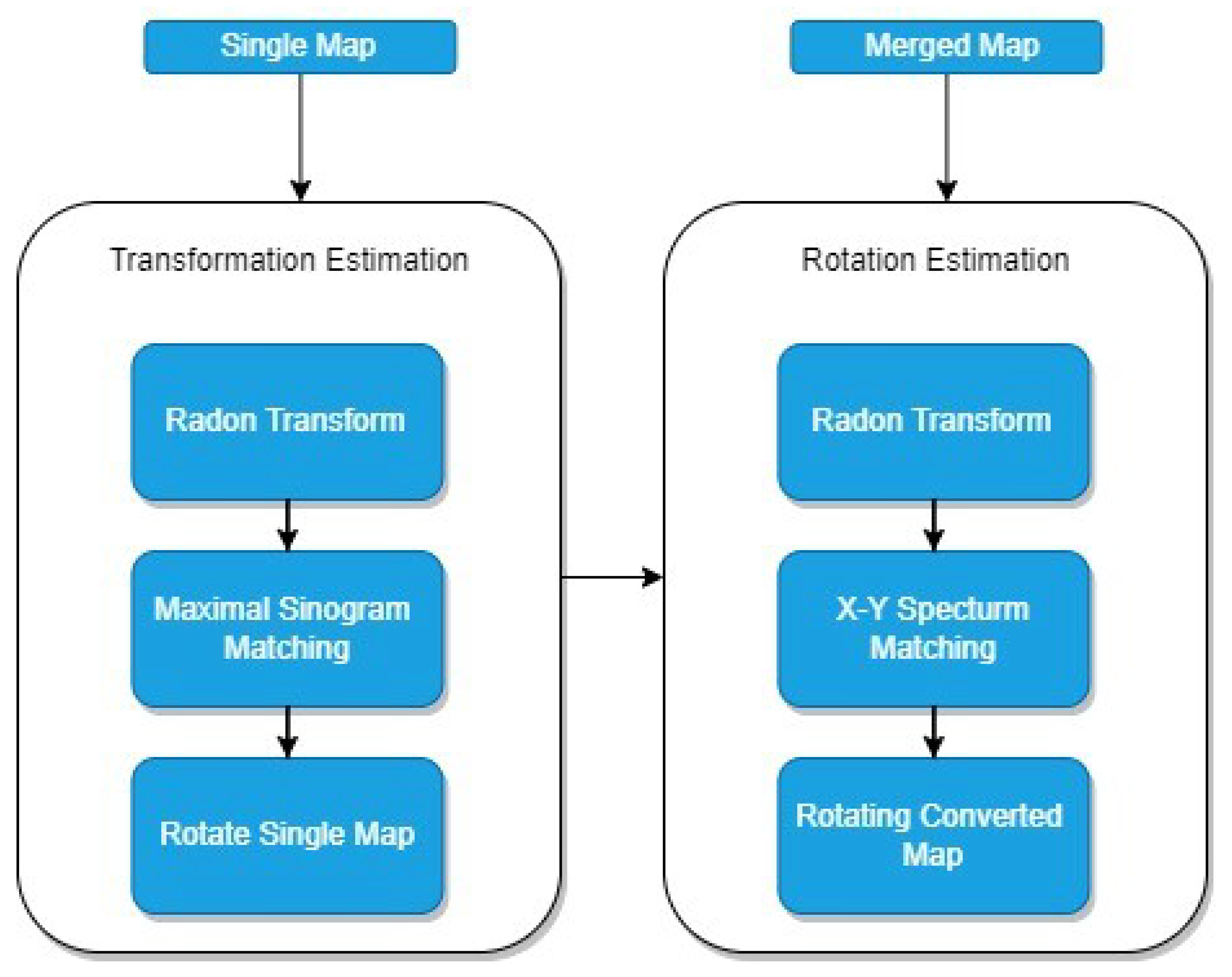
After the maps were created, they were merged by the Radon transform algorithm. Radon transformation is used to extract geometric information from a map according to offsets and rotation [
39]. Sinogram-based map aggregation was performed using Radon transform. Sinogram-based map assembly consists of two consecutive parts, as shown in
Figure 16.
The rotation angle and the offset amounts are estimated by maximum sinogram matching and partial sinogram matching in the sinogram-based map merging. First, the map rotation between the two maps is estimated: Delta Theta and then Delta
x and Delta
y offsets between them are estimated. The Radon transform of the Dirac delta function is often referred to as a sinogram because the graph of a sine wave supports its distribution. Let
f(
x,
y) be a continuous function in R2 disappearing outside a large disk.
f(
x,
y) is a continuous function zeroing on circular surface R2. A straight line in this plane, denoted by L, is parameterized as follows:
where
t is a parameter for the parametric form of L, s is L’s distance from the origin, and Alfa is the normal vector’s angle to the x-axis. In Radon transform,
RTf is a function on the space of straight lines of L in R2, defined by a line integral along each such line
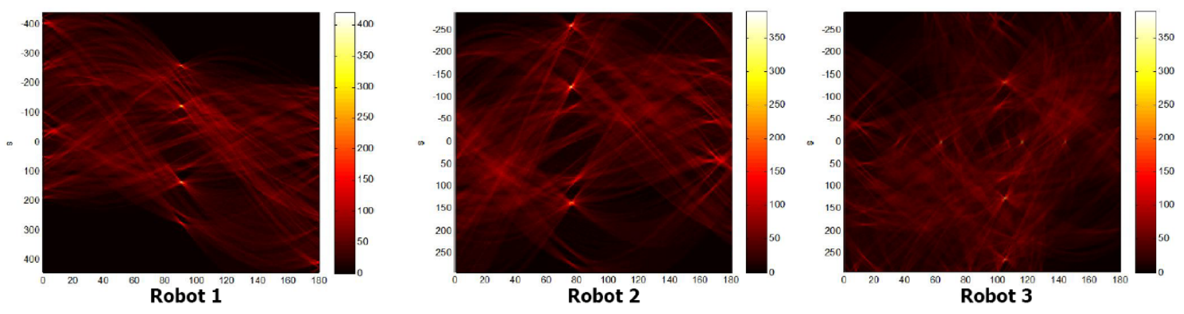
Sinograms of the scanned areas are shown in
Figure 17. The structure of a sensor on the robot is shown visually and graphically in
Figure 18 and
Figure 19.
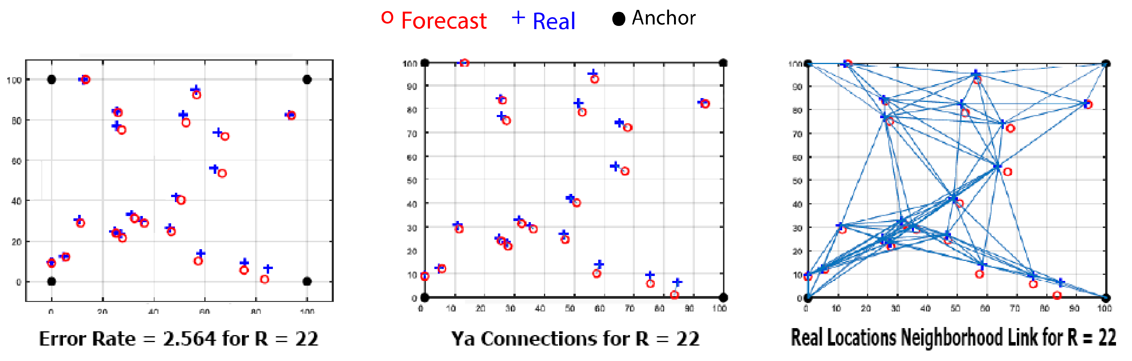
They were tested with three robots in a virtual environment. Robots can create a new map by sharing the RP-lidar information they obtained by communicating with each other. Using the BA, they send instant location information to other robots every 2 s, enabling them to share location information simultaneously. In this way, a robot can perform mapping more quickly by avoiding the areas where the other robot has already scanned. The error function in Equation (
11) is used to calculate the error between the estimated node positions and the actual node positions while mapping.
Here (N) represents the number of target nodes, (
Yi) the estimated target node coordinates, and (
xi,
yi) the target node’s coordinates. The coordinate information obtained from the simulated setting is used in this formula, and different algorithms’ error rates have been calculated. The positions of 20 predicted and actual nodes in simulation1 and the neighbouring connection obtained by their combination are shown in
Figure 20.
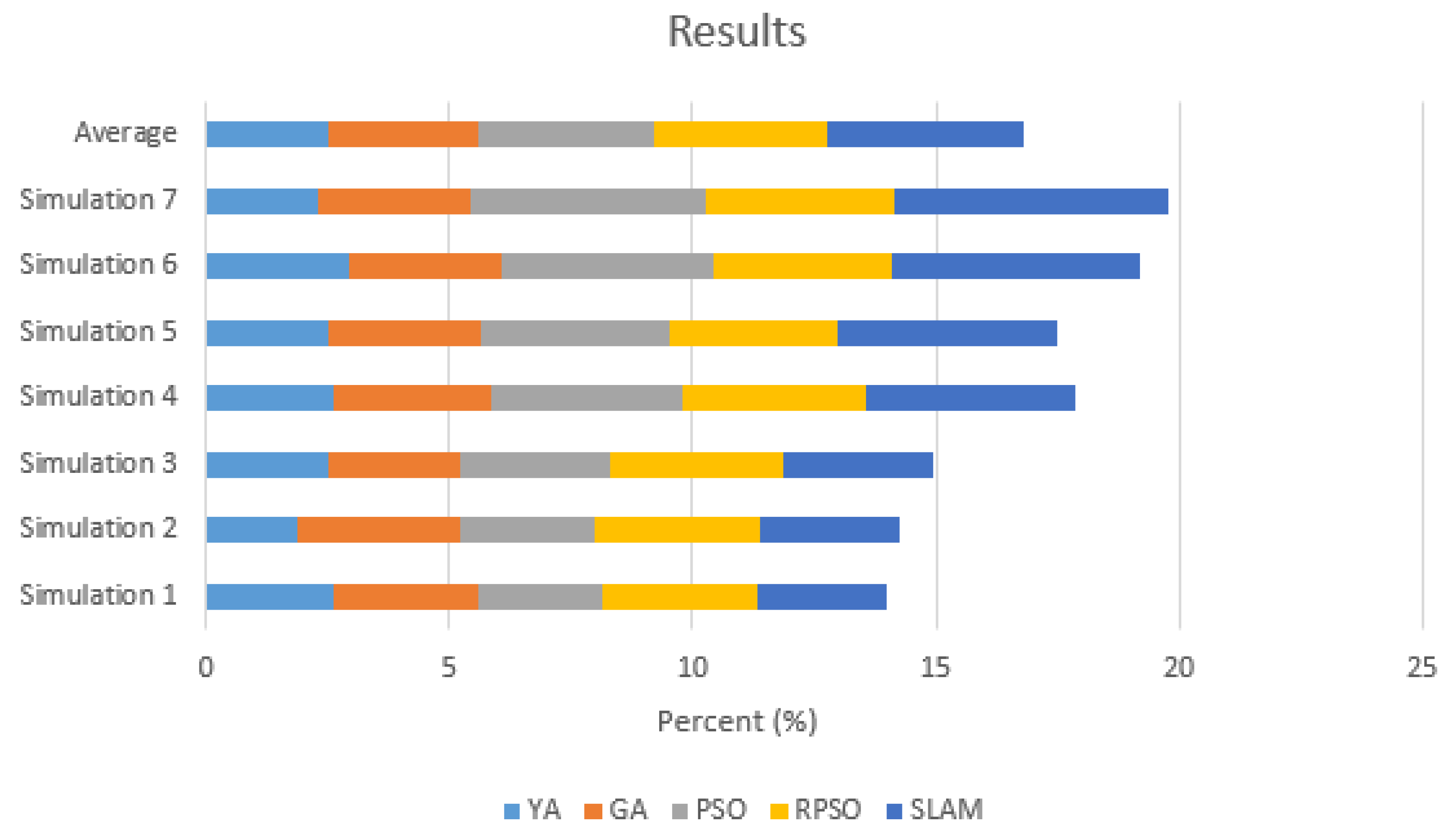
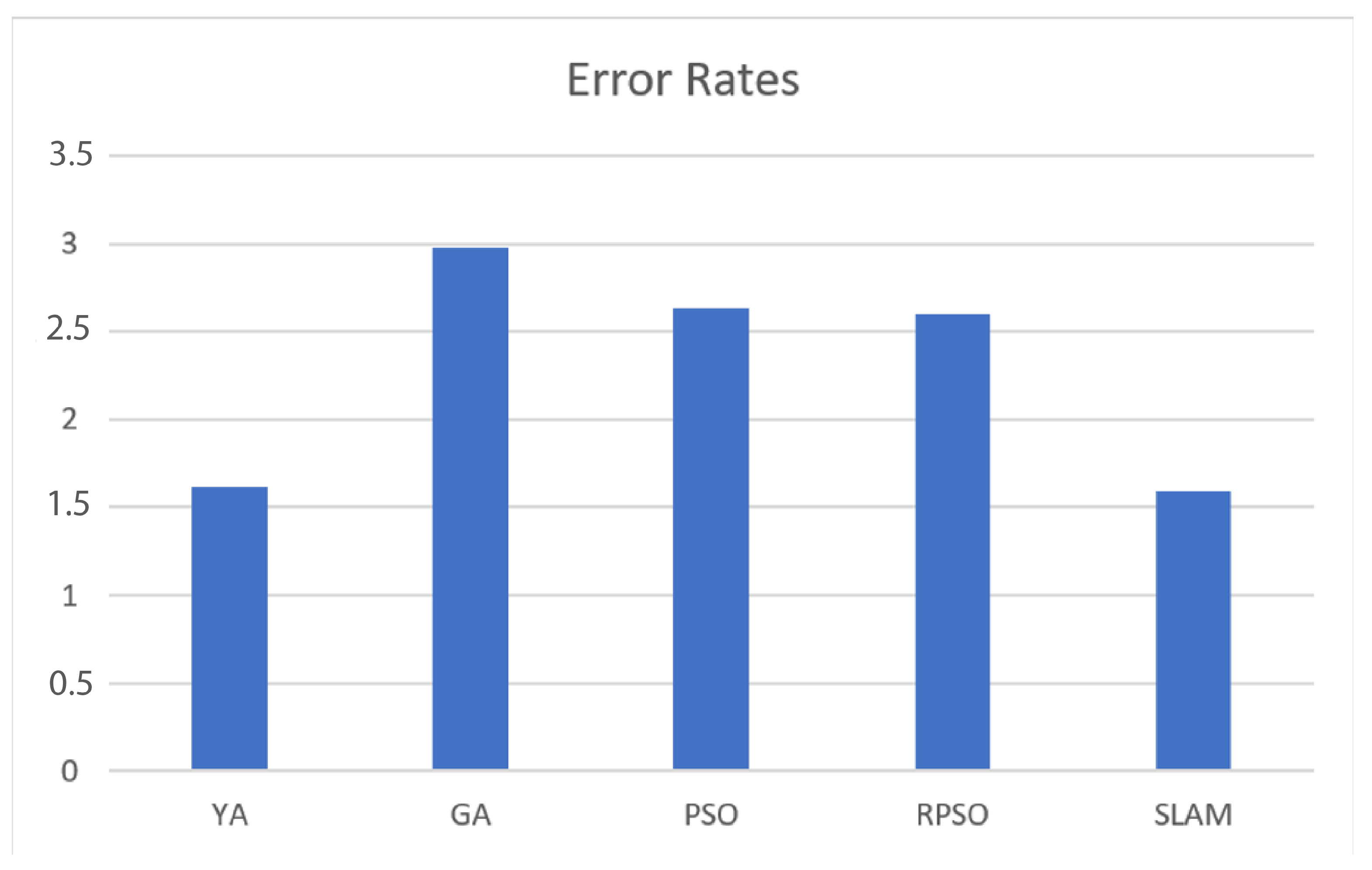
The iteration results used for different simulation settings are shown in
Figure 21, and the average error rates for 50 simulations are shown in
Figure 22.
The scope of the scanning process can be increased by using more advanced sensors in the future to improve the effectiveness of the study. In addition, an educational model can be developed using the old data, making direction determination automatic. In the long term, autonomous flying robots can be integrated into the team in areas where robots cannot move (For example, in an environment with flooding or high water level). Joint search and rescue activities can be carried out with the Disaster and Emergency Management Presidency (AFAD), established in our country in 2009, to implement the system described in the study.


