
Design of a Modified Compact Coupler with Unwanted Harmonics Suppression for L-Band Applications

 ,
, 
 ,
, 
Abstract
:1. Introduction
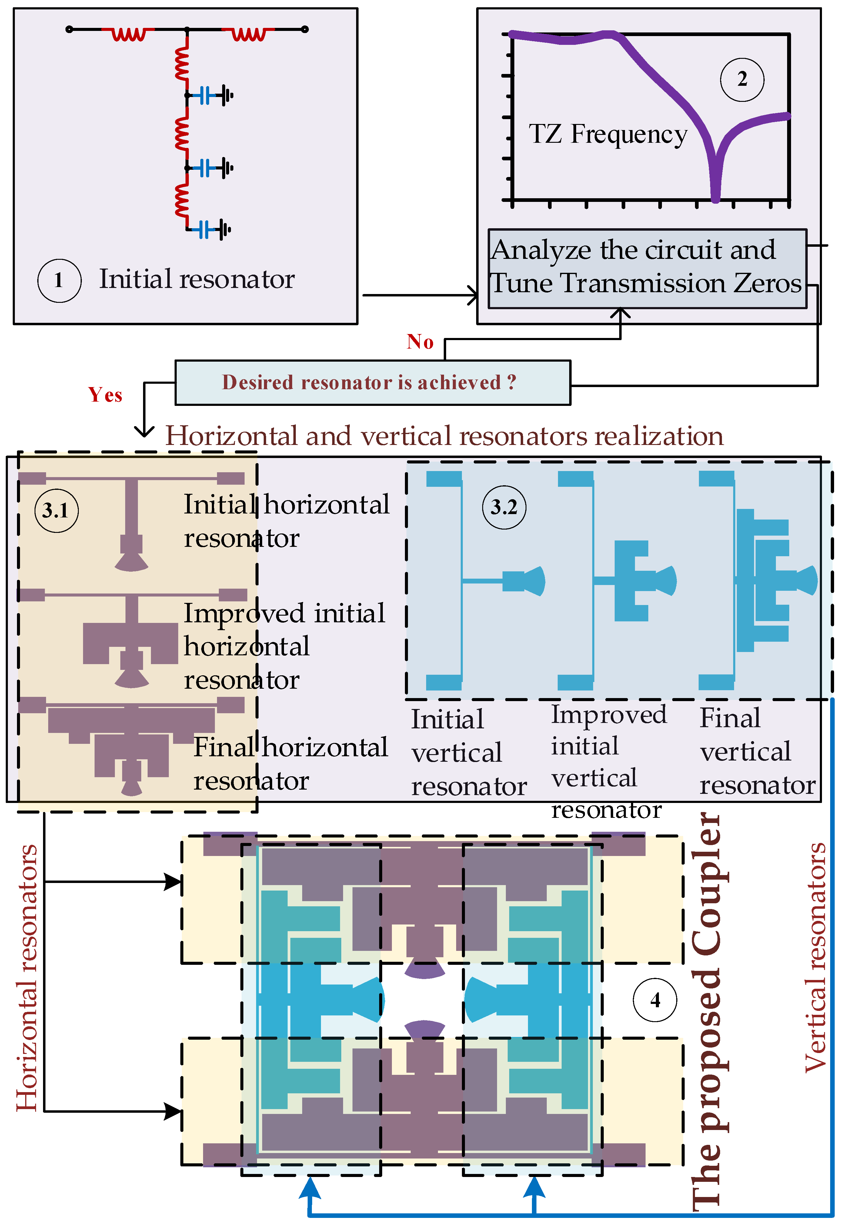
2. Design Procedure
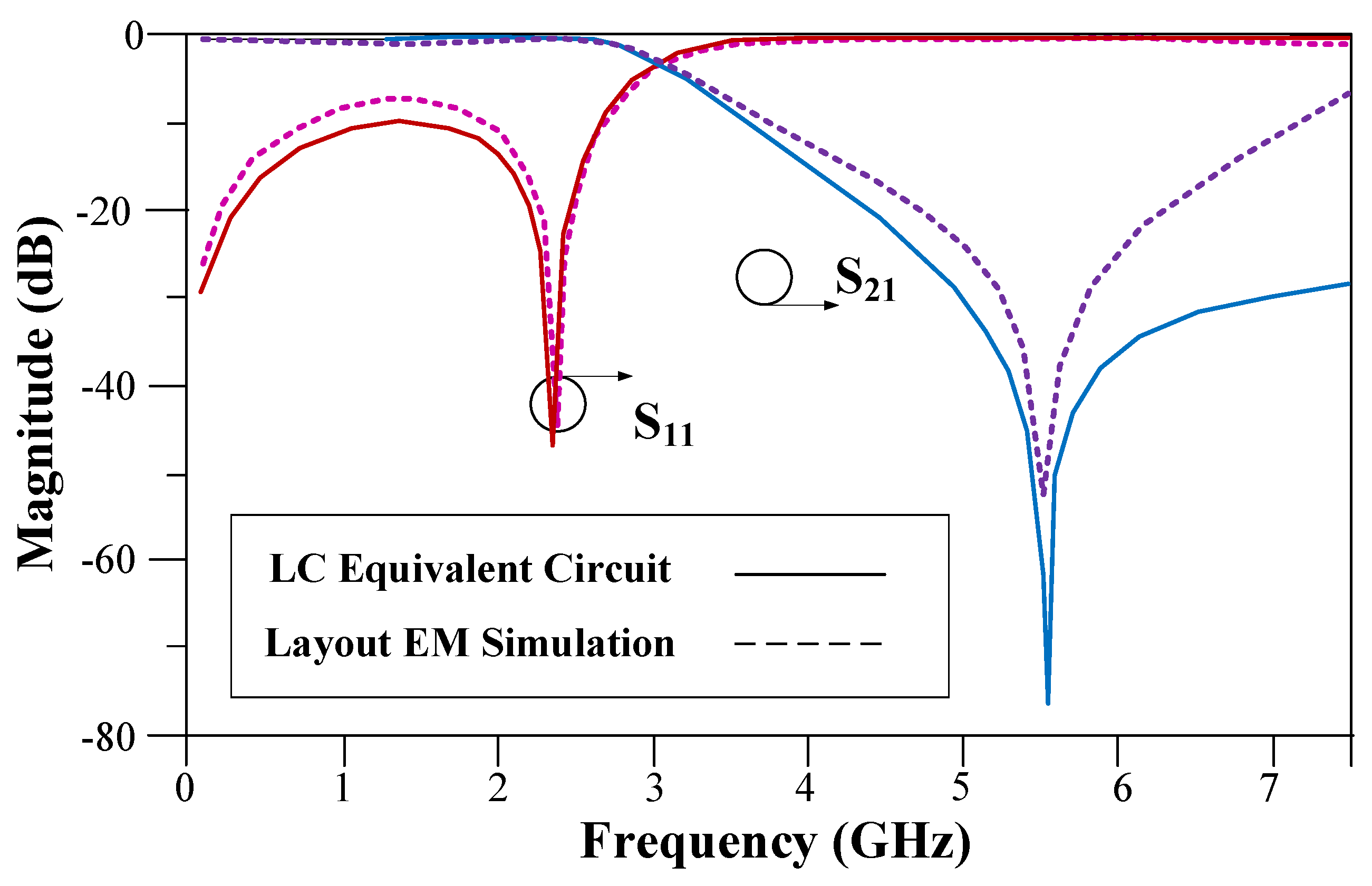
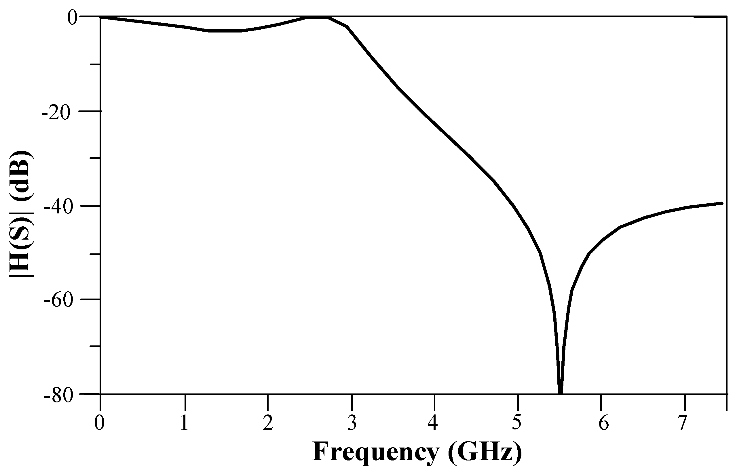
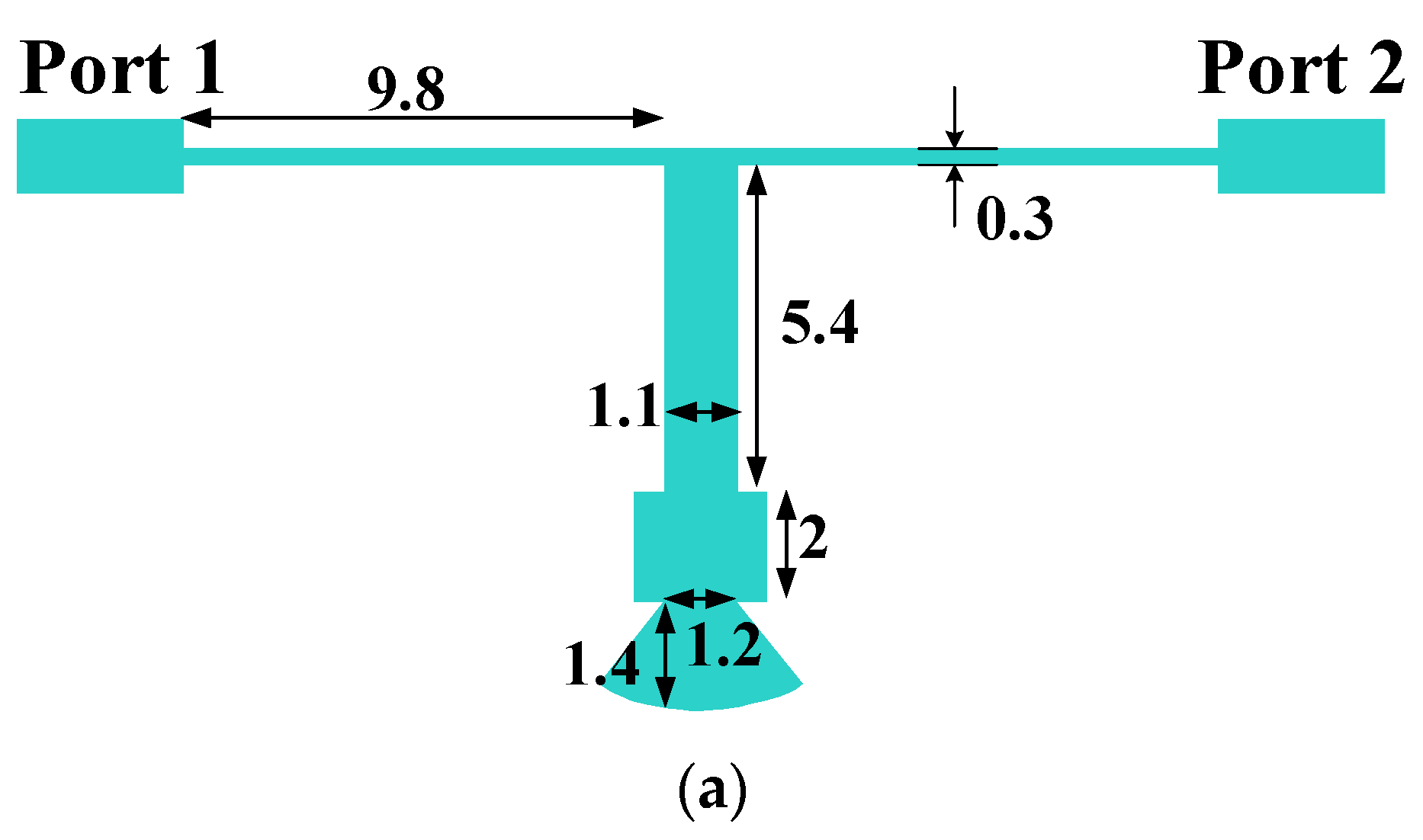
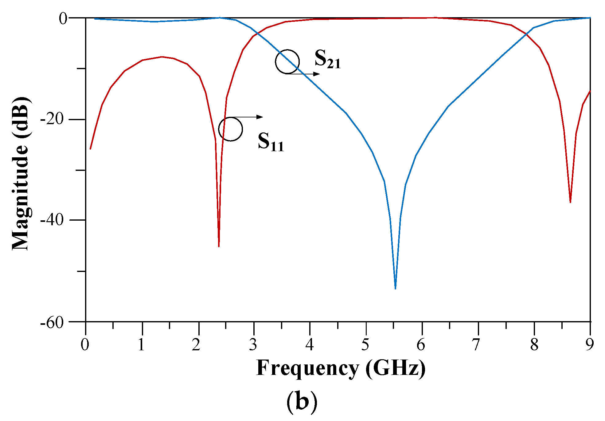
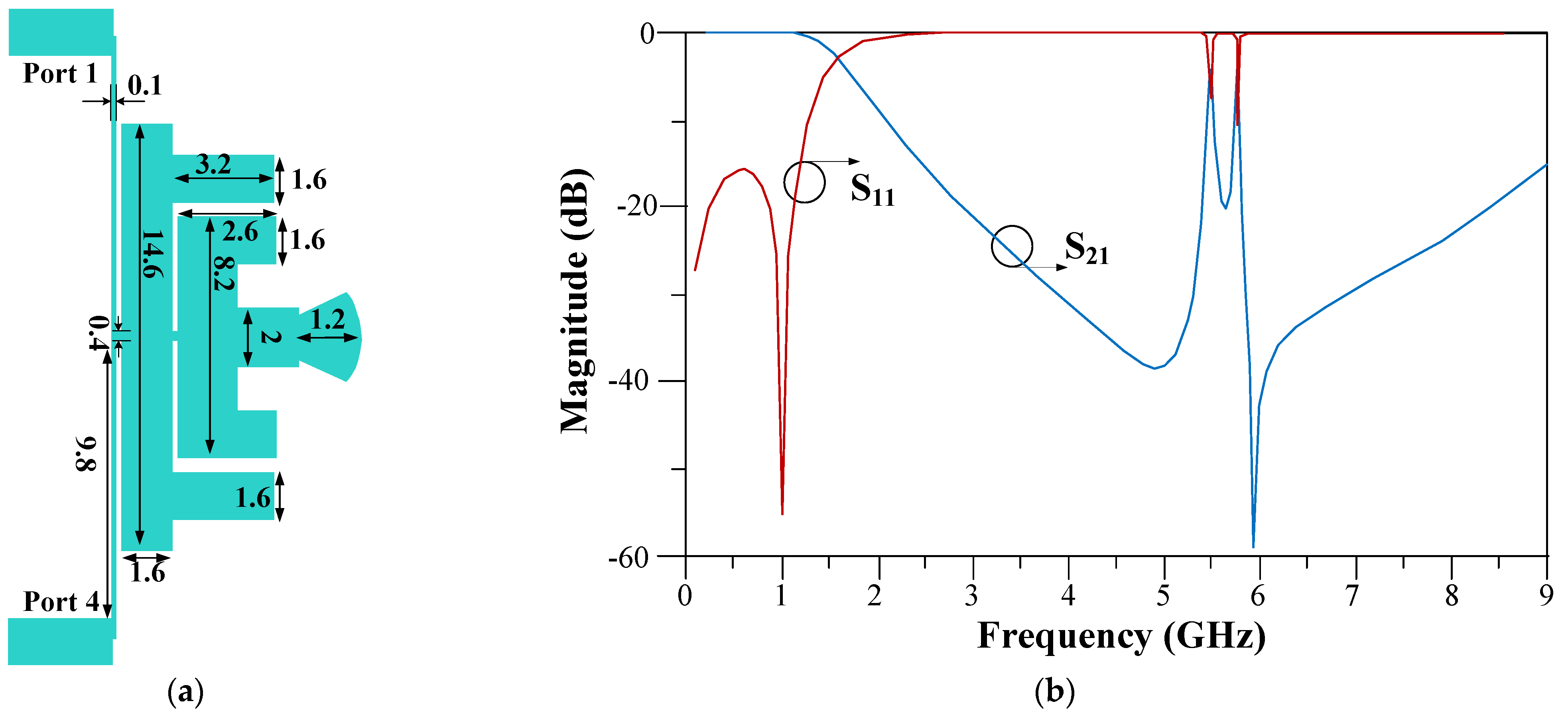
2.1. Horizontal Resonator Design
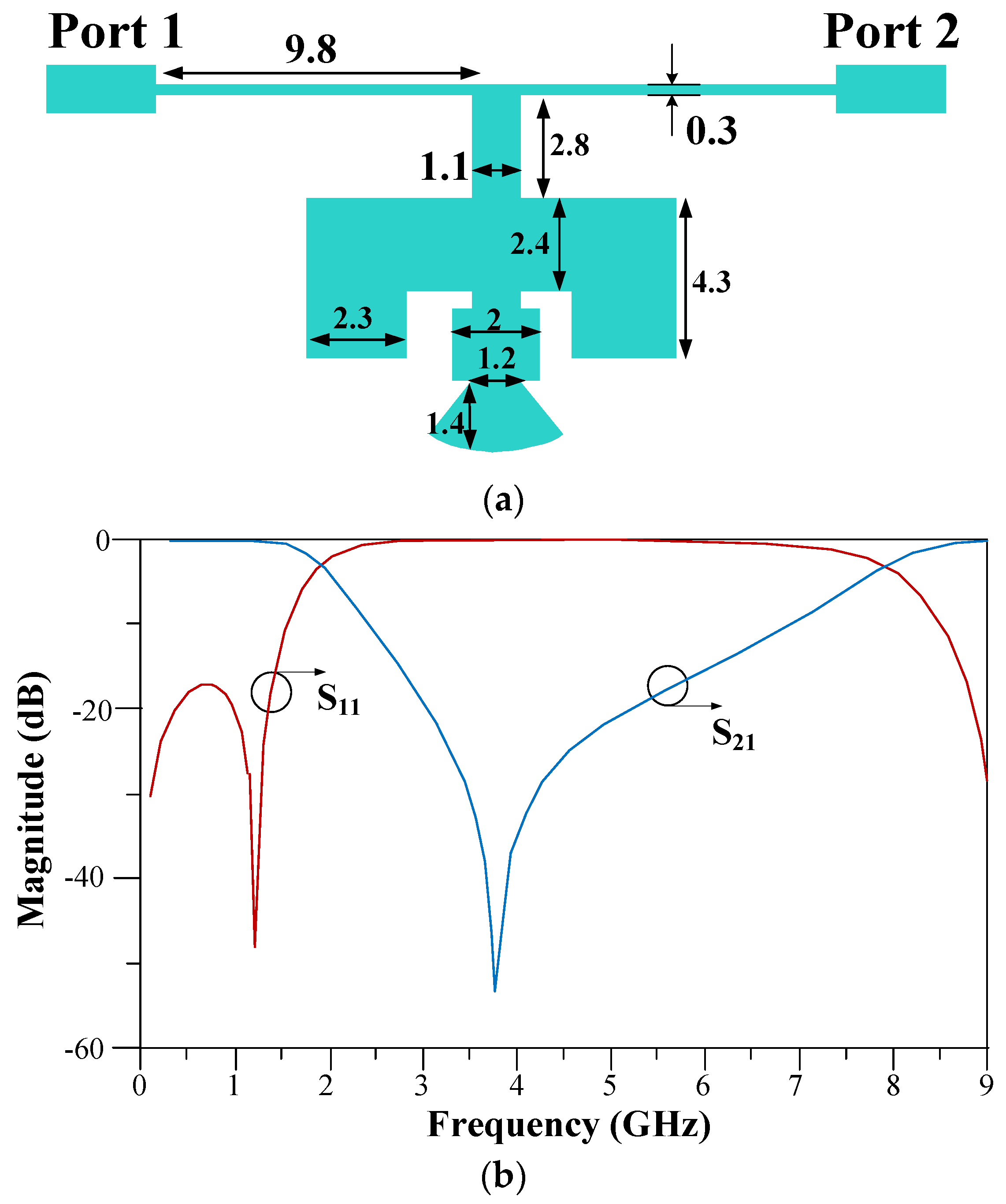
2.2. Vertical Resonator Design
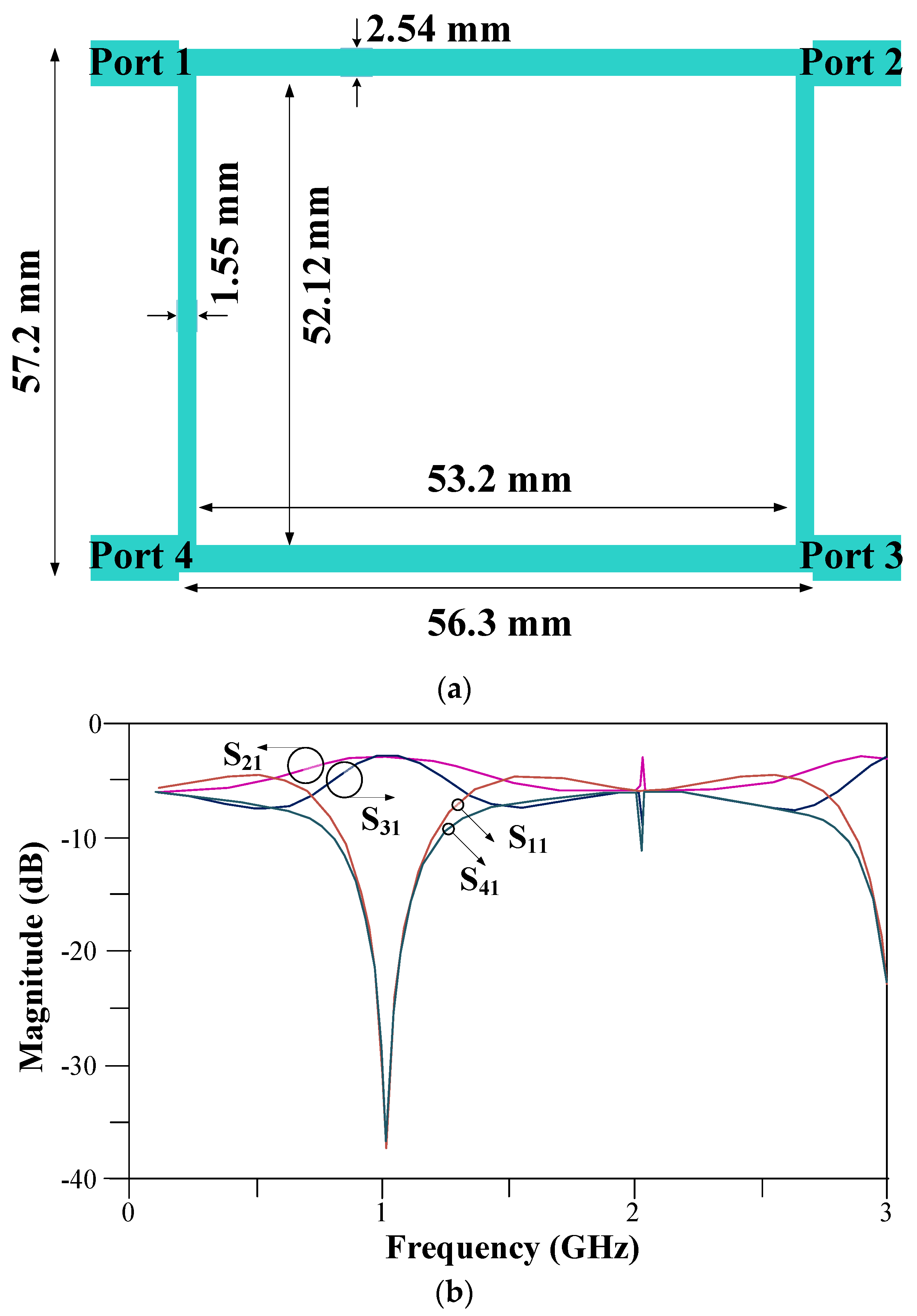
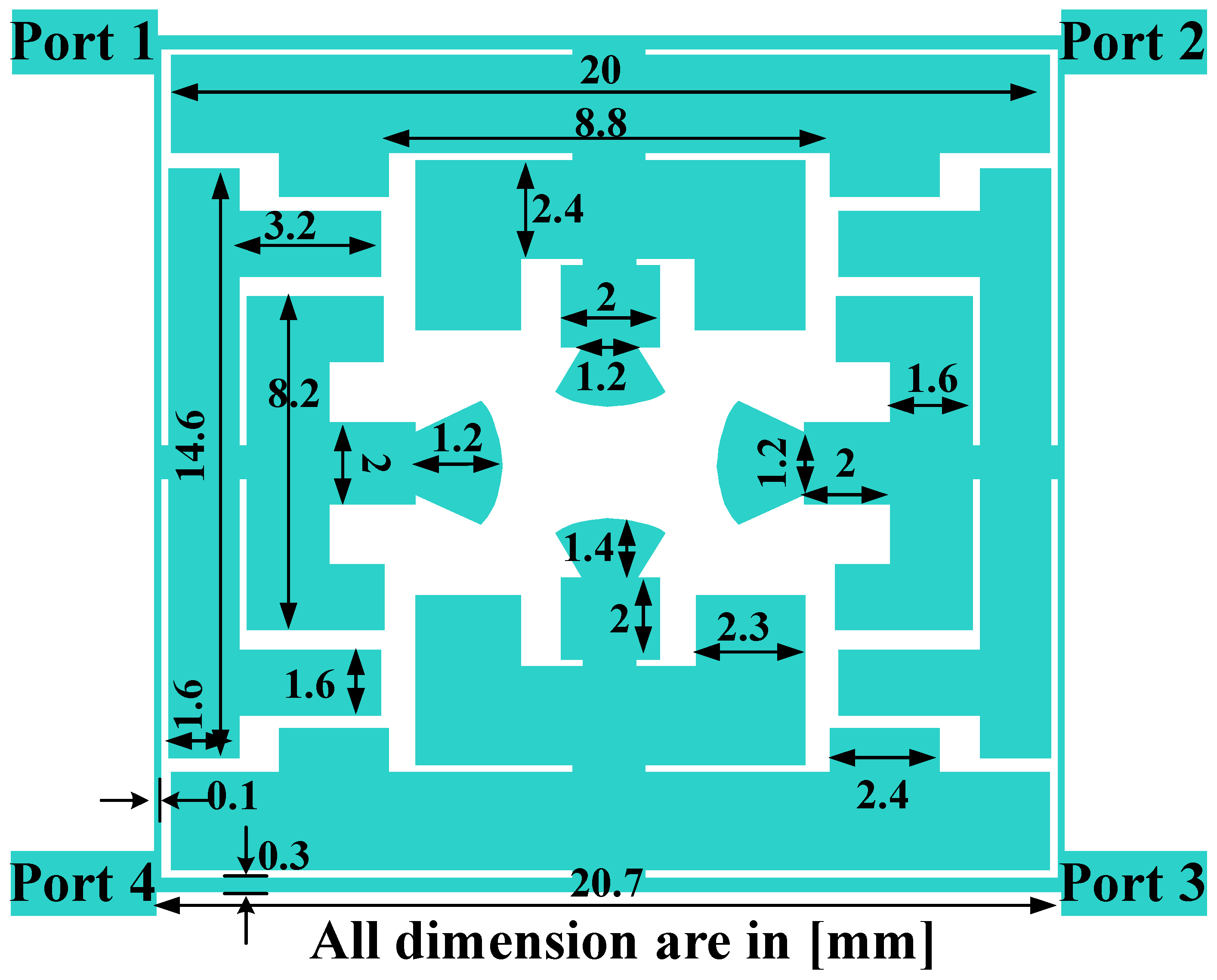
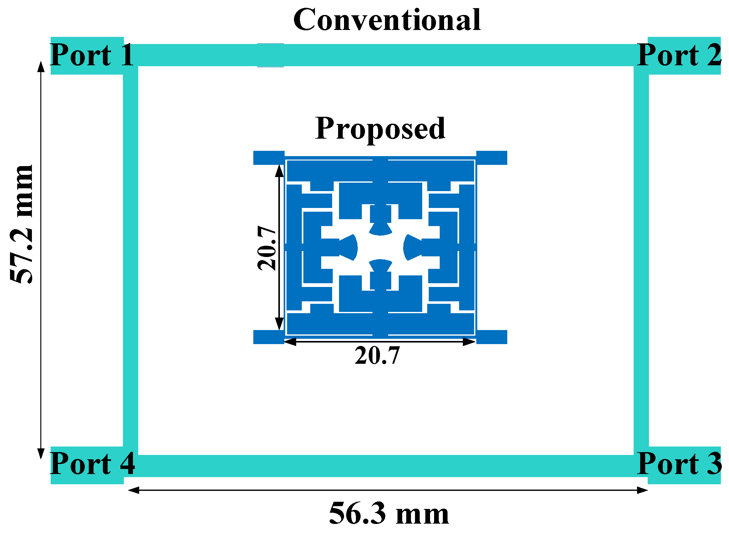
3. Design of The Proposed BLC
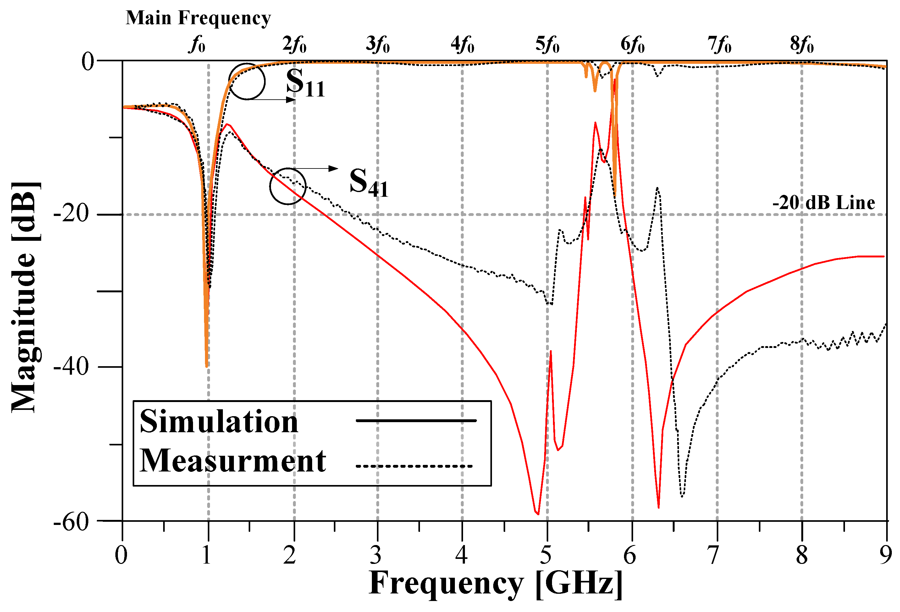
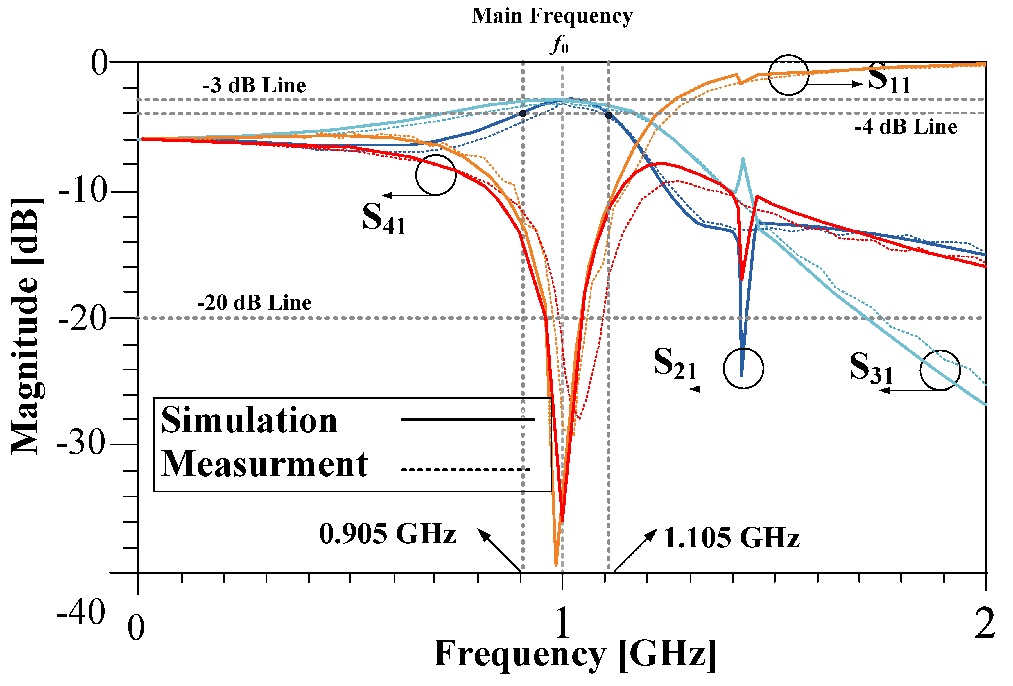
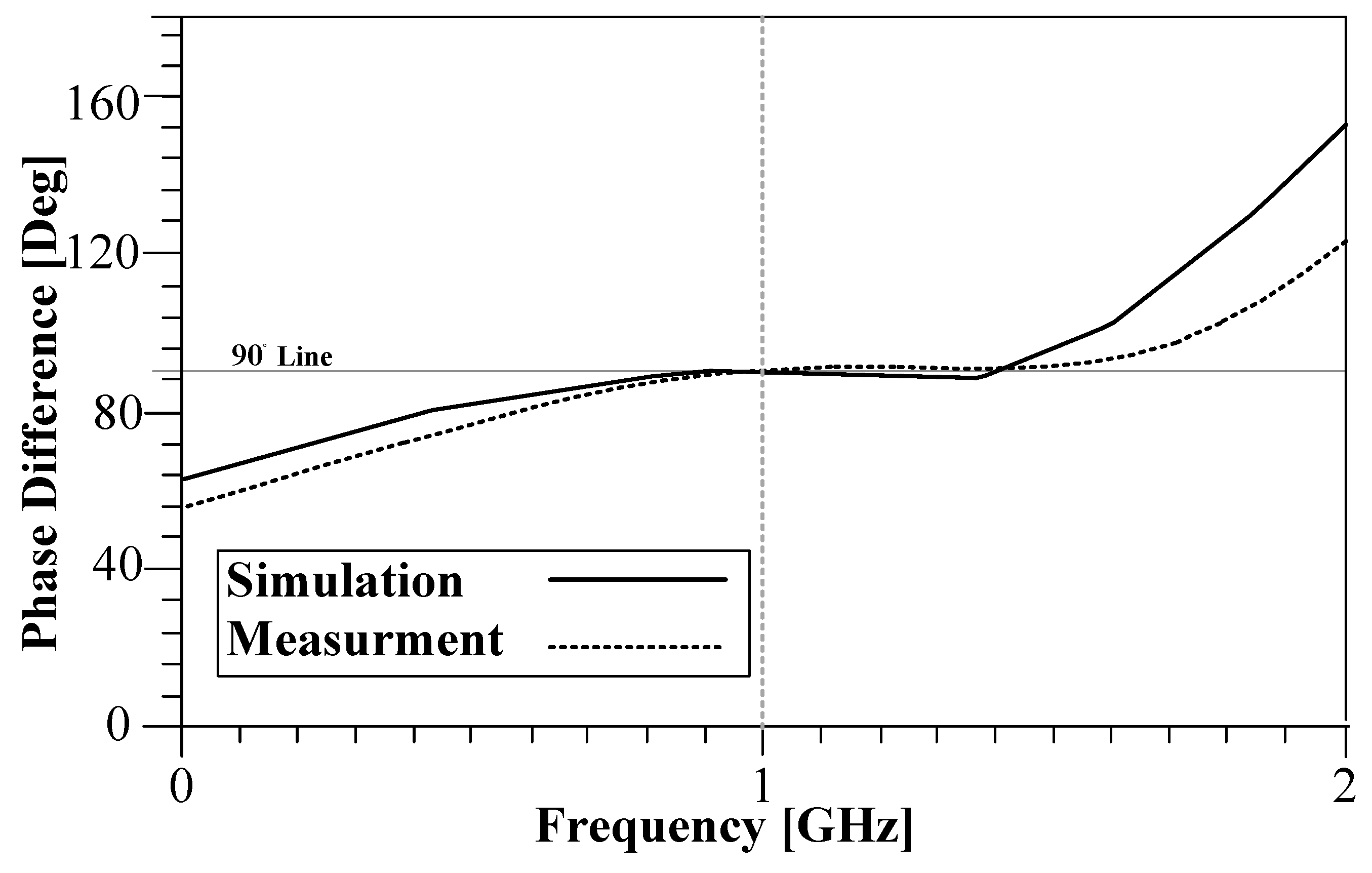
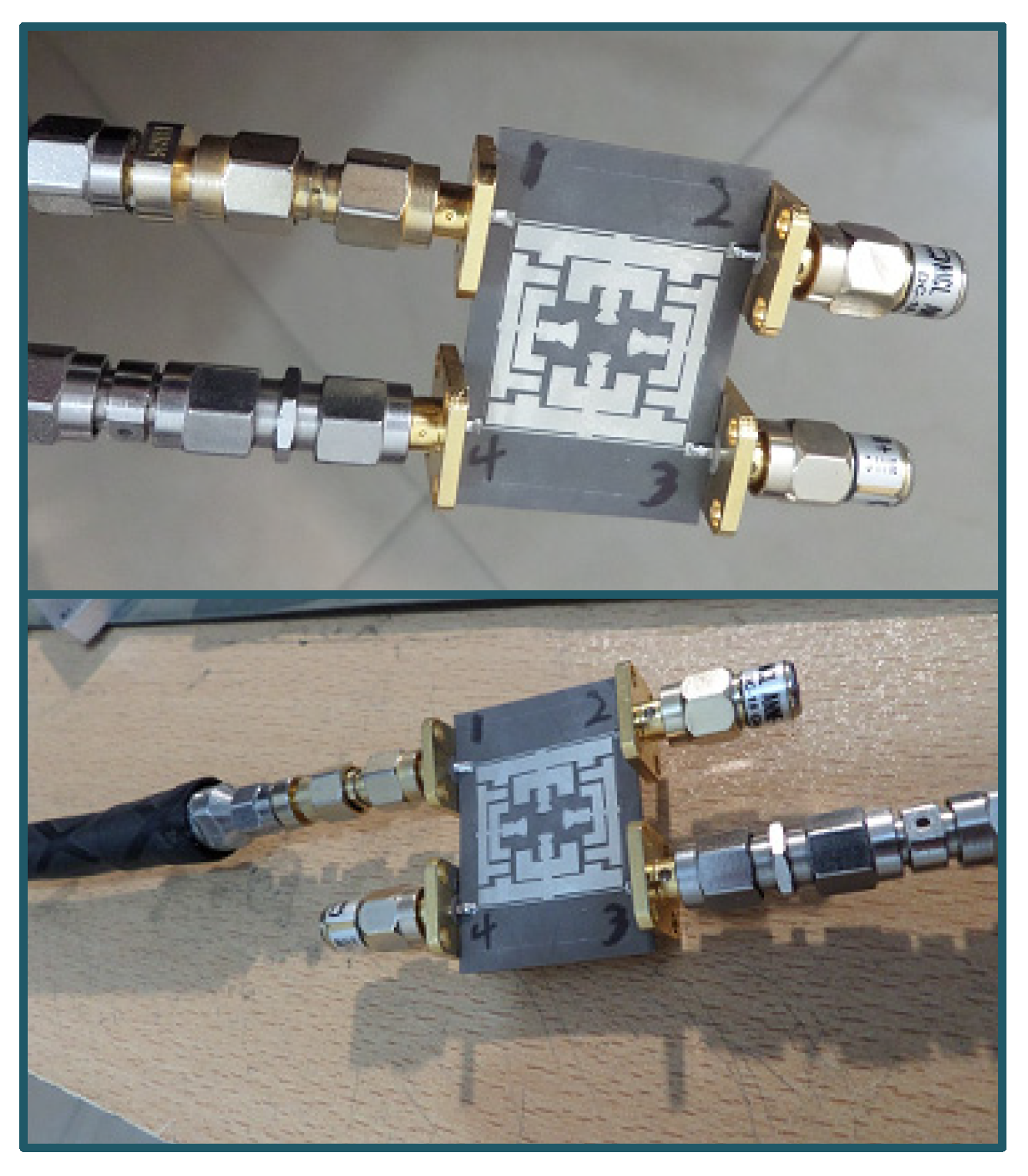
Results of The Proposed BLC
4. Conclusions
Author Contributions
Funding
Data Availability Statement
Conflicts of Interest
References
- Salh, A.; Audah, L.; Abdullah, Q.; Aydogdu, O.; Alhartomi, M.A.; Alsamhi, S.H.; Almalki, F.A.; Shah, N.S.M. Low Computational Complexity for Optimizing Energy Efficiency in mm-wave Hybrid Precoding System for 5G. IEEE Access 2021, 10, 4714–4727. [Google Scholar] [CrossRef]
- Lalbakhsh, A.; Mohamadpour, G.; Roshani, S.; Ami, M.; Roshani, S.; Sayem, A.S.; Alibakhshikenari, M.; Koziel, S. Design of a Compact Planar Transmission Line for Miniaturized Rat-Race Coupler with Harmonics Suppression. IEEE Access 2021, 9, 129207–129217. [Google Scholar] [CrossRef]
- Powell, J.R.; Shepphard, D.J.; Quaglia, R.; Cripps, S.C. A Power Reconfigurable High-Efficiency X-Band Power Amplifier MMIC Using the Load Modulated Balanced Amplifier Technique. IEEE Microw. Wirel. Compon. Lett. 2018, 28, 527–529. [Google Scholar] [CrossRef]
- Kizilbey, O.; Palamutçuogullari, O.; Yarman, S.B. 3.5–3.8 GHz classE balanced GaNHEMT power amplifier with 20 W Pout and 80% PAE. IEICE Electron. 2013, 10, 20130104. [Google Scholar] [CrossRef] [Green Version]
- Mohyuddin, W.; Kim, I.B.; Choi, H.C.; Kim, K.W. Design of A Compact Single-Balanced Mixer for UWB Applications. J. Electromagn. Eng. Sci. 2017, 17, 65–70. [Google Scholar] [CrossRef] [Green Version]
- Zhang, Z.; Cheng, Z.; Liu, G. A Power Amplifier with Large High-Efficiency Range for 5G Communication. Sensors 2020, 20, 5581. [Google Scholar] [CrossRef] [PubMed]
- Jamshidi, M.B.; Roshani, S.; Talla, J.; Roshani, S.; Peroutka, Z. Size reduction and performance improvement of a microstrip Wilkinson power divider using a hybrid design technique. Sci. Rep. 2021, 11, 7773. [Google Scholar] [CrossRef]
- Lalbakhsh, A.; Alizadeh, S.M.; Ghaderi, A.; Golestanifar, A.; Mohamadzade, B.; Jamshidi, M.B.; Mandal, K.; Mohyuddin, W. A Design of a Dual Band Bandpass Filter Based on Modal Analysis for Modern Communication Systems. Electronics 2020, 9, 1770. [Google Scholar] [CrossRef]
- Lalbakhsh, A.; Neyestanak, A.A.L.; Naser-Moghaddasi, M. Microstrip Hairpin Bandpass Filter Using Modified Minkowski Fractal for Suppression of Second Harmonic. IEICE Trans. Electron. 2012, 95, 78–381. [Google Scholar] [CrossRef]
- Lalbakhsh, A.; Jamshidi, M.B.; Siahkamari, H.; Ghaderi, A.; Golestanifar, A.; Linhart, R.; Talla, J.; Simorangkir, R.B.V.B.; Mandal, K. A Compact Lowpass Filter for Satellite Communication Systems Based on Transfer Function Analysis. AEU Int. J. Electron. Commun. 2020, 124, 153318. [Google Scholar] [CrossRef]
- Sun, K.O.; Ho, S.J.; Yen, C.C.; Van Der Weide, D. A compact branch line coupler using discontinuous microstrip lines. IEEE Microw. Wirel. Compon. Lett. 2005, 15, 519–520. [Google Scholar] [CrossRef]
- Liao, S.S.; Pen, J.T. Compact planar microstrip branch line couplers using the quasi lumped elements approach with non-symmetrical and symmetrical T-shaped structure. IEEE Trans. Microw. Theory Tech. 2006, 54, 3508–3514. [Google Scholar] [CrossRef]
- Kurgan, P.; Filipcewicz, J.; Kitlinski, M. Development of a compact microstrip resonant cell aimed at efficient microwave component size reduction. IET Microw. Antennas Propag. 2012, 6, 1291–1298. [Google Scholar] [CrossRef]
- Sedighy, S.H.; Khalaj Amirhosseini, M. Compact branch line coupler using step impedance transmission lines (SITLs). Appl. Comput. Electromagn. Soc. J. 2013, 28, 866–870. [Google Scholar]
- Tsai, K.-Y.; Yang, H.-S.; Chen, J.-H.; Chen, Y.-J. A Miniaturized 3 dB Branch-Line Hybrid Coupler with Harmonics Suppression. IEEE Microw. Wirel. Compon. Lett. 2011, 21, 537–539. [Google Scholar] [CrossRef]
- Wang, J.; Wang, B.-Z.; Guo, Y.; Ong, L.C.; Xiao, S. A Compact Slow-Wave Microstrip Branch-Line Coupler with High Performance. IEEE Microw. Wirel. Compon. Lett. 2007, 17, 501–503. [Google Scholar] [CrossRef]
- Barik, R.K.; Rajender, R.; Karthikeyan, S.S. A Miniaturized Wideband Three-Section Branch-Line Hybrid with Harmonic Suppression Using Coupled Line and Open-Ended Stubs. IEEE Microw. Wirel. Compon. Lett. 2017, 27, 1059–1061. [Google Scholar] [CrossRef]
- Nie, W.; Xu, K.-D.; Zhou, M.; Xie, L.-B.; Yang, X.-L. Compact narrow/wide band branch-line couplers with improved upper-stopband. AEU Int. J. Electron. Commun. 2018, 98, 45–50. [Google Scholar] [CrossRef]
- Krishna, I.S.; Barik, R.K.; Karthikeyan, S.; Kokil, P. A miniaturized harmonic suppressed 3 dB branch line coupler using H-shaped microstrip line. Microw. Opt. Technol. Lett. 2017, 59, 913–918. [Google Scholar] [CrossRef]
- Kumar, K.V.; Karthikeyan, S.S. Miniaturised quadrature hybrid coupler using modified T-shaped transmission line for wide-range harmonic suppression. IET Microw. Antennas Propag. 2016, 10, 1522–1527. [Google Scholar] [CrossRef]
- Hazeri, A.R.; Kashaninia, A.; Faraji, T.; Arani, M.F. Miniaturization and harmonic suppression of the branch-line coupler based on radial stubs. IEICE Electron. Express 2011, 8, 736–741. [Google Scholar] [CrossRef] [Green Version]
- Lian, G.; Wang, Z.; He, Z.; Zhong, Z.; Sun, L.; Yu, M. A New Miniaturized Microstrip Branch-Line Coupler with Good Harmonic Suppression. Prog. Electromagn. Res. Lett. 2017, 67, 61–66. [Google Scholar] [CrossRef] [Green Version]
- Kim, J.-S.; Kong, K.-B. Compact Branch-Line Coupler for Harmonic Suppression. Prog. Electromagn. Res. 2010, 16, 233–239. [Google Scholar] [CrossRef] [Green Version]
- Choi, K.-S.; Yoon, K.-C.; Lee, J.-Y.; Lee, C.-K.; Kim, S.-C.; Kim, K.-B.; Lee, J.-C. Compact branch-line coupler with harmonics suppression using meander T-shaped line. Microw. Opt. Technol. Lett. 2014, 56, 1382–1384. [Google Scholar] [CrossRef]
- Sattari, M.A.; Roshani, G.H.; Hanus, R.; Nazemi, E. Applicability of time-domain feature extraction methods and artificial intelligence in two-phase flow meters based on gamma-ray absorption technique. Measurement 2021, 168, 108474. [Google Scholar] [CrossRef]
- Roshani, M.; Sattari, M.A.; Ali, P.J.M.; Roshani, G.H.; Nazemi, B.; Corniani, E.; Nazemi, E. Application of GMDH neural network technique to improve measuring precision of a simplified photon attenuation based two-phase flowmeter. Flow Meas. Instrum. 2020, 75, 101804. [Google Scholar] [CrossRef]
- Jamshidi, M.B.; Lalbakhsh, A.; Mohamadzade, B.; Siahkamari, H.; Mousavi, S.M. A novel neural-based approach for design of microstrip filters. AEU-Int. J. Electron. Commun. 2019, 110, 152847. [Google Scholar] [CrossRef]
- Luo, L.; Tie, H.; Ma, Q.; Zhou, B. Compact LTCC Filter with 7th-Order Harmonics Suppression for 5G N77 Band Applications. Prog. Electromagn. Res. Lett. 2021, 98, 69–74. [Google Scholar] [CrossRef]
- Barik, R.K.; Koziel, S.; Szczepanski, S. Wideband Highly-Selective Bandpass Filtering Branch-Line Coupler. IEEE Access 2022, 10, 20832–20838. [Google Scholar] [CrossRef]
- Maheswari, S.; Jayanthy, T. Design of Compact Branch-Line Coupler for Wi-Max Applications. Int. J. Microw. Opt. Technol. 2022, 17, 68–73. [Google Scholar]
- Kumar, K.V.P.; Alazemi, A.J. A Flexible Miniaturized Wideband Branch-Line Coupler Using Shunt Open-Stubs and Meandering Technique. IEEE Access 2021, 9, 158241–158246. [Google Scholar] [CrossRef]


| LC Horizontal | ||||||
|---|---|---|---|---|---|---|
| L0 | L1 | L2 | L3 | C1 | C2 | C3 |
| 4.1 nH | 0.6 nH | 0.4 nH | 0.3 nH | 0.5 pF | 0.4 pF | 0.2 pF |
| Refs. | Frequency (GHz) | Insertion Loss (dB) | Harmonic Suppression | Size Reduction | Advantage | Technique |
|---|---|---|---|---|---|---|
| [11] | 1 | N/A | No | 60% | Size reduction | Discontinuous microstrip lines |
| [12] | 2.4 | N/A | No | 70% | Size Reduction | Quasi-lumped elements approach |
| [14] | 1 | 0.33 | No | 50% | Size reduction | Step impedance transmission line |
| [15] | 0.836 | 0.9 | No | 74% | Size reduction | Branch-line hybrid coupler |
| [16] | 2 | 0.36 | 2ƒ0 | 72% | Size reduction Wideband | Slow wave |
| [18] | 2.45 | 0.45 | 2ƒ0 to 5ƒ0 | 55% | Harmonic suppression | L-shaped Open stubs |
| [19] | 0.9 | 0.3 | 2ƒ0 to 4ƒ0 | 64% | Size reduction Wideband | H-shaped microstrip line |
| [22] | 0.96 | 0.3 | 2ƒ0 to 6ƒ0 | 80% | Size reduction | Eight open ended stubs |
| [23] | 1 | 0.3 | 2ƒ0 and 3ƒ0 | 63% | Size reduction | Spiral open stubs |
| [24] | 2.1 | 0.9 | 2ƒ0 and 3ƒ0 | 63% | Size reduction | Spiral T-shaped lines |
| [29] | 3.5 GHz | 0.5 | 2ƒ0 | No | Wideband Filtering | Coupled lines Open Stubs |
| [30] | 3.5 GHz | 0.5 | No | 35% | Size reduction | Pi-Network |
| [31] | 0.9 | 0.76 | No | 36% | Size reduction Flexible | Open stub Meander lines |
| This work | 1 | 0.2 | 2ƒ0 to 5ƒ0 | 86% | Size reduction harmonic suppression | T-shaped resonators, Open stubs, Step impedance, and Radial stubs |
Publisher’s Note: MDPI stays neutral with regard to jurisdictional claims in published maps and institutional affiliations. |
© 2022 by the authors. Licensee MDPI, Basel, Switzerland. This article is an open access article distributed under the terms and conditions of the Creative Commons Attribution (CC BY) license (https://creativecommons.org/licenses/by/4.0/).
Share and Cite
Roshani, S.; Yahya, S.I.; Roshani, S.; Farahmand, A.H.; Hemmati, S. Design of a Modified Compact Coupler with Unwanted Harmonics Suppression for L-Band Applications. Electronics 2022, 11, 1747. https://doi.org/10.3390/electronics11111747
Roshani S, Yahya SI, Roshani S, Farahmand AH, Hemmati S. Design of a Modified Compact Coupler with Unwanted Harmonics Suppression for L-Band Applications. Electronics. 2022; 11(11):1747. https://doi.org/10.3390/electronics11111747
Chicago/Turabian StyleRoshani, Saeed, Salah I. Yahya, Sobhan Roshani, Amir Hossein Farahmand, and Siroos Hemmati. 2022. "Design of a Modified Compact Coupler with Unwanted Harmonics Suppression for L-Band Applications" Electronics 11, no. 11: 1747. https://doi.org/10.3390/electronics11111747
APA StyleRoshani, S., Yahya, S. I., Roshani, S., Farahmand, A. H., & Hemmati, S. (2022). Design of a Modified Compact Coupler with Unwanted Harmonics Suppression for L-Band Applications. Electronics, 11(11), 1747. https://doi.org/10.3390/electronics11111747